

Page 1

®
ProRide Diagnostic
ProRide Diagnostic PL
Wheel Balancer Models
See
ÌBalancing Your
First Tire
on page 5.
Safety Instructions
Set-up Instructions
Operation Instructions
Maintenance Instructions
READ these instructions before placing unit in
service. KEEP these and other materials delivered
with the unit in a binder near the machine for ease
of reference by supervisors and operators.
1601 J. P. Hennessy Drive, LaVergne, TN USA 37086-3565 615/641-7533 800/688/6359 www.ammcoats.com Manual Part No.: 85607587 00
HENNESSY INDUSTRIES INC. Manufacturer of AMMCO
®
, COATS® and BADA® Automotive Service Equipment and Tools. Revision: 07/11
Page 2

IMPORTANT SAFETY INSTRUCTIONS
READ ALL INSTRUCTIONS
1. Eye and face protection recommendations:
“Protective eye and face equipment is required to
be used where there is a reasonable probability
of injury that can be prevented by the use of
such equipment.” O.S.H.A. 1910.133(a) Protective
goggles, safety glasses, or a face shield must be
provided by the owner and worn by the operator
of the equipment. Care should be taken to see
that all eye and face safety precautions are followed by the operator. ALWAYS WEAR SAFETY
GLASSES. Everyday glasses only have impact
resistant lenses, they are not safety glasses.
2. Do not disable hood safety interlock system, or in
any way shortcut safety controls and operations.
3. Be sure that wheels are mounted properly, the
hub nut engages the arbor for not less than four
(4) turns, and the hub nut is firmly tightened
before spinning the wheel.
4. Read and understand this manual before operating. Abuse and misuse will shorten the functional
life.
5. Be sure the balancer is properly connected to the
power supply and electrically grounded.
6. Do not operate equipment with a damaged cord
or if the equipment has been dropped or damaged – until it has been examined and repaired by
a qualified serviceman.
7. Do not let cord hang over edge of table, bench, or
counter or come in contact with hot manifolds or
moving fan blades.
8. If an extension cord is necessary, a cord with a
current rating equal to or more than that of the
equipment should be used. Cords rated for less
current than the equipment may overheat. Care
should be taken to arrange the cord so that it will
not be tripped over or pulled.
10. Wear proper clothing. Safety toe, non-slip footwear and protective hair covering to contain hair
is recommended. Do not wear jewelry, loose
clothing, neckties, or gloves when operating the
balancer.
11. Keep work area clean and well lighted. Cluttered
and/or dark areas invite accidents.
12. Avoid dangerous environments. Do not use power
tools or electrical equipment in damp or wet locations, or expose them to rain.
13. Avoid unintentional starting. Be sure the balancer
is turned off and power disconnected before
servicing.
14. Disconnect the balancer before servicing.
15. Use only manufacturer’s recommended accessories. Improper accessories may result in personal
injury or property damage.
16. Repair or replace any part that is damaged or worn
and that may cause unsafe balancer operation. Do
not operate damaged equipment until it has been
examined by a qualified service technician.
17. Never overload or stand on the weight tray or any
part of the balancer.
18. Do not allow untrained persons to operate machinery.
19. To reduce the risk of fire, do not operate equipment in the vicinity of open containers or flammable liquids (gasoline).
20. Adequate ventilation should be provided when
working on or operating internal combustion
engines.
21. Keep hair, loose clothing, fingers, and all parts of
body away from moving parts.
22. Use equipment only as described in this manual.
9. Keep guards and safety features in place and in
working order.
23. Use only manufacturer’s recommended attachments and accessories.
SAVE THESE INSTRUCTIONS
ii • Important: Always read and follow instructions.
Page 3
Owner’s Responsibility
To maintain machine and user safety, the responsibility
of the owner is to read and follow these instructions:
Definitions of Hazard Levels
Identify the hazard levels used in this manual with the
following definitions and signal words:
• Follow all installation instructions.
• Make sure installation conforms to all applicable
Local, State, and Federal Codes, Rules, and Regulations; such as State and Federal OSHA Regulations
and Electrical Codes.
• Carefully check the unit for correct initial function.
• Read and follow the safety instructions. Keep them
readily available for machine operators.
• Make certain all operators are properly trained,
know how to safely and correctly operate the unit,
and are properly supervised.
• Allow unit operation only with all parts in place and
operating safely.
• Carefully inspect the unit on a regular basis and
perform all maintenance as required.
• Service and maintain the unit only with authorized
or approved replacement parts.
• Keep all instructions permanently with the unit
and all decals/labels/notices on the unit clean and
visible.
• Do not override safety features.
Operator Protective Equipment
Personal protective equipment helps make tire servicing safer. However, equipment does not take the
place of safe operating practices. Always wear durable
work clothing during tire service activity. Loose fitting
clothing should be avoided. Tight fitting leather gloves
are recommended to protect operator’s hands when
handling worn tires and wheels. Sturdy leather work
shoes with steel toes and oil resistant soles should be
used by tire service personnel to help prevent injury
in typical shop activities. Eye protection is essential
during tire service activity. Safety glasses with side
shields, goggles, or face shields are acceptable. Back
belts provide support during lifting activities and are also
helpful in providing operator protection. Consideration
should also be given to the use of hearing protection if
tire service activity is performed in an enclosed area, or
if noise levels are high.
DANGER
Watch for this symbol:
DANGER
It Means: Immediate hazards, which will result in
severe personal injury or death.
WARNING
Watch for this symbol:
WARNING
It Means: Hazards or unsafe practices, which could
result in severe personal injury or death.
CAUTION
Watch for this symbol:
CAUTION
It Means: Hazards or unsafe practices, which may
result in minor personal injury or product or property
damage.
Watch for this symbol! It means BE ALERT! Your
safety, or the safety of others, is involved!
Important: Always read and follow instructions. • iii
Page 4

Safety Notices and Decals
WARNING
Failure to follow danger, warning, and caution
instructions may lead to serious personal
injury or death to operator or bystander or
damage to property. Do not operate this
machine until you read and understand all
the dangers, warnings and cautions in this
manual. For additional copies of either, or
further information, contact:
Hennessy Industries, Inc.
1601 JP Hennessy Drive
LaVergne, TN 37086-3565
(615) 641-7533 or (800) 688-6359
www.ammcoats.com
Standard Safety Devices
• STOP key for stopping the wheel under emergency
conditions.
• A hood guard of high impact plastic that is designed
to prevent the counterweights from flying out in any
direction except towards the floor.
• A hood switch interlock system that prevents the
machine from starting if the guard is not lowered
and stops the wheel whenever the guard is raised.
iv • Important: Always read and follow instructions.
Page 5

Table of Contents
Important Safety Instructions ................................. ii
Owner’s Responsibility ............................................iii
Operator Protective Equipment ...............................iii
Definitions of H azard Levels ....................................iii
Safety Notices and Decals ......................................iv
Standard Safety Devices .........................................iv
Setup Instructions .................................................... 2
Receiving ................................................................. 2
Electrical Requirements .......................................... 2
Air Supply Connection ............................................. 2
Machine Set-up ....................................................... 3
Floor and Space Requirements ............................... 3
Connect to Power .................................................... 3
Specifications ............................................................ 4
Features ..................................................................... 4
Balancing Your First Tire ........................................... 5
Principle Operating Parts ......................................... 6
Know Your Unit ........................................................ 6
Power Switch........................................................... 7
Using The Offset Arm .............................................. 7
Using The Laser Locator .......................................... 7
Wheel Guard ........................................................... 7
Positioning Pedal ..................................................... 7
Auto Wheel Lock Feature (PL Version Only) ............ 7
Control Panel ........................................................... 8
Balancer Function Set-up and Review ................... 9
Video Screen Flowchart ........................................... 9
Screen-Saver Mode ................................................. 9
Home Screen .........................................................10
User Memory .........................................................10
Menu Screen ..........................................................11
General Set-up Screen .......................................... 12
Balancing Set-up Screen ....................................... 13
Special Functions Screen ...................................... 14
Printer Screen ........................................................ 14
Mounting Wheel on Spindle Shaft ........................ 14
Standard Back Cone Mounting .............................. 14
Standard Front Cone Mounting ............................. 15
Alternate Mounting ............................................... 15
Pneumatic Shaft (PL Version Only)) ....................... 15
Setting Wheel Dimensions (DIM) .......................... 16
Definition of Dimensions (DIM) ............................. 16
Wheel Data Entry .................................................. 16
Balancing A Wheel .................................................. 18
Dynamic Balancing ................................................ 18
Static Balancing ..................................................... 18
Attaching Corrective Weights ................................ 19
Measurement Result ............................................. 19
Measurement Result Screen Options ................... 19
Behind Spoke ........................................................ 20
Indicate Exact Corrective Weight Position ............. 21
Match Balance (Optimization) ............................... 22
Match Balance (Optimization) ................................ 22
Sonar LR Instruction .............................................. 24
Calibration Program ............................................... 25
Arm Calibration ...................................................... 25
Machine Calibration ............................................... 25
Diagnostic Procedures ........................................... 25
After Balance Vibration Problems .......................... 25
Troubleshooting ...................................................... 26
Maintenance Instructions ...................................... 28
Glossary ................................................................... 28
NOTICE
Read entire manual before assembling,
installing, operating, or servicing this
equipment.
Important: Always read and follow instructions. • 1
Page 6

Set-up Instructions
Receiving
The shipment should be thoroughly inspected as soon
as it is received. The signed bill of lading is acknowledgement, for the carrier, of receipt in good condition
of the shipment covered by our invoice.
If any of the goods called for on this bill of lading are
shorted or damaged, do not accept them until the carrier makes a notation of the shorted or damaged goods
on the freight bill. Do this for your own protection.
NOTIFY THE CARRIER AT ONCE if any hidden loss or
damage is discovered after receipt and request him to
make an inspection. If the carrier will not do so, prepare
an affidavit to the effect that you have so notified the
carrier (on a certain date) and that he has failed to
comply with your request.
IT IS DIFFICULT TO COLLECT FOR LOSS OR DAMAGE AFTER YOU HAVE GIVEN THE CARRIER A CLEAR
RECEIPT.
File your claim with the carrier promptly. Support
your claim with copies of the bill of lading, freight bill,
invoice, and photographs, if possible.
Electrical Requirements
See serial tag for the appropriate power requirements
of your machine.
Always have a qualified electrician install the proper
receptacles in accordance with state and local codes.
Air Supply Connection
The wheel balancer requires a minimum 8 CFM clean/
dry air source at 115 PSI. This system is only intended
for operation of the spindle with pneumatic locking. The
connection fitting is located at the back of the machine.
At least 8 Kg/cm2 (~ 0.8 MPa; ~ 8 BAR; ~ 115 PSI)
pressure is needed for correct operation of the release
device.
Although COATS responsibility ceases upon delivery
of the shipment to the carrier, we will gladly assist
in tracing lost shipments. Our willingness to assist in
every possible manner does not make COATS responsible for collection of claims, or replacement of lost or
damaged materials.
2 • Important: Always read and follow instructions.
Page 7
Machine Set-up
CAUTION
Do not use the control panel, control panel
base, accessory storage, faceplate, hood or
shaft to lift the balancer.
CAUTION
Do not attempt to install and set-up the unit
yourself. Contact COATS as noted below.
A factory trained COATS Service Technician must perform the install, set-up, and initial test procedures on
your wheel balancer. Do not attempt to install and setup the unit yourself. Accurate and reliable operation of
your unit depends on proper installation. Please contact
COATS directly at 1-800-688-9240 for the Certified
Service Partner nearest you.
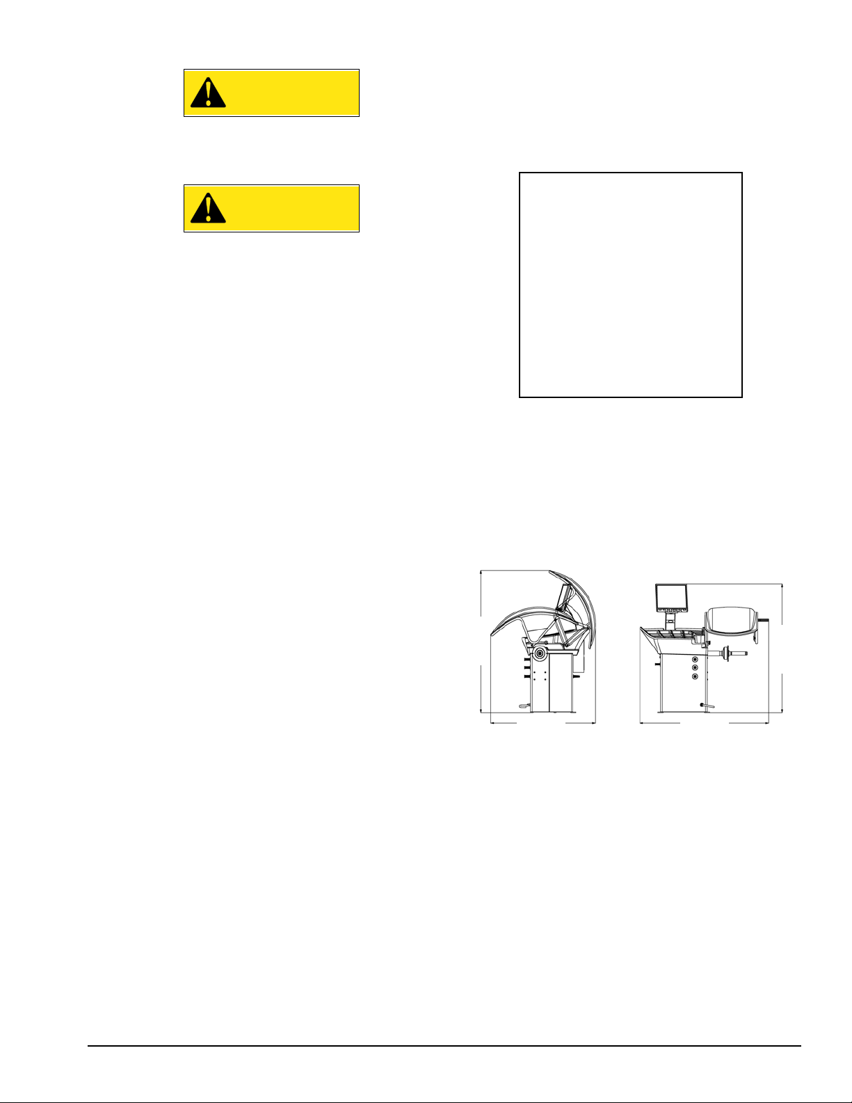
Floor and Space Requirements
The balancer must be located on a flat floor of solid
construction, preferably concrete. The balancer must
sit solidly on its three feet. If the balancer is not level,
does not sit solidly on its three feet, or is placed on an
unstable floor, the balancer will not function properly
and may produce inaccurate balance readings.
Do not operate the balancer while it is on the pallet.
Select a location for the balancer that provides a level,
solid floor, and adequate clearance around and above
the balancer. Make sure the location selected has
enough room above and behind the unit so the hood
can be raised completely. The location must also provide working room for mounting and removing wheels.
Make sure the area has adequate lighting.
66-inches
(1664mm)
49-inches
(1230mm)
60-inches
(1513mm)
59-inches
Connect to Power
Your factory trained COATS® Service Technician should
do the final check to verify the power installation before
connecting the balancer to a power supply. Failure due
to improper power connection may void the warranty.
Important: Always read and follow instructions. • 3
(1505mm)
Page 8

Specifi cations
Features
Wheel Diameter Range
10 - 30 inches (264 - 762 mm)
Wheel Width Range
2 - 19 inches (51 - 483 mm)
Maximum Outside Tire Diameter
Up to 42 inches (1067 mm)
Maximum Tire/Wheel Weight
160 pounds (73 Kg)
Mounting Shaft Diameter
40 mm
Resolution (Round Off Mode)
0.25 ounce, position 1.40 degrees
Resolution (Non-Round Off Mode)
0.01 ounce, position 1.40 degrees
Balancing Display Increments
0.25 or 0.01 ounces
Electrical Requirements
115V, 1 Ph, 50/60 Hz, 15A
NEMA L5-15P
(use grounding type plug)
• 3-D Auto Data Entry
• Simple, Interactive User Interface
• Auto Hood Start
• Static-On-Screen™ Display
• Direct Tape-A-Weight
• Pneumatic Mounting (Option)
• Radial Runout Measurement
• Lateral Runout Measurement (Option)
• Static, Dynamic And Multiple Tape-A-Weight
• Laser Guided Operation™
®
Application
®
Air Source Requirement (PL Version Only)
115-145 PSI (8-10 Bar)
(air line water separator required)
Footprint
Width: 44.5 inches (1130 mm)
Depth: 48.5 inches (1230 mm)
Height: 65.5 inches (1664 mm)
Shipping Weight
275 pounds (125 Kg)
(without accessories)
4 • Important: Always read and follow instructions.
Page 9
★Balancing Your First Tire
1. Turn the machine OFF then ON.
The machine wakes up at the Home
Screen using standard clip-on wheel
weight locations (Clip 1 & Clip 2) and
wheel dimensions.
8. Turn wheel in direction of inboard arrow
until this symbol appears:
Note: If an inboard corrective weight is not
required the measurement will read - - -, go
to step 10.
9. Attach inboard corrective weight.
2. Mount a tire/wheel onto balancer that
will use standard clip-on wheel weights.
Use the most appropriate mounting method.
3. Always remove any weights already
attached to the wheel.
4. Use offset arm to enter A & D wheel
dimensions automatically.
Pull offset arm out to the wheel, hold it still at clip-on
weight position against wheel flange, and wait for BEEP.
Return arm to home position.
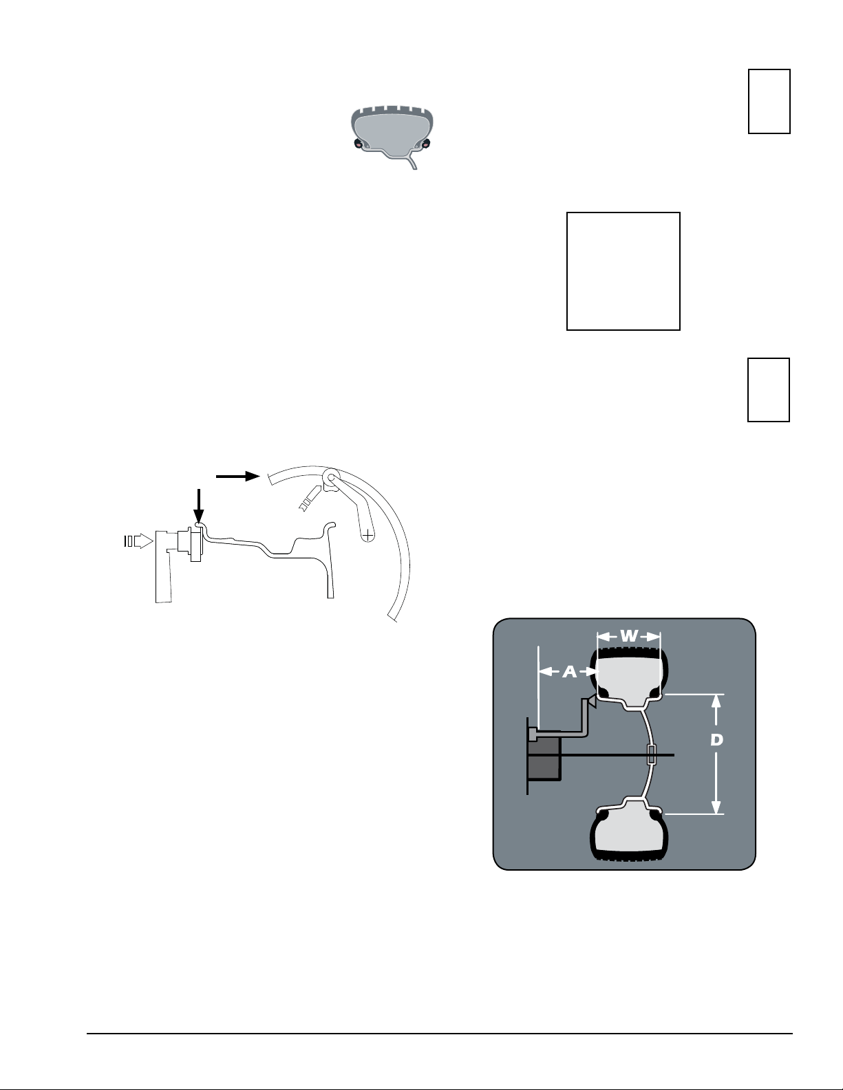
Clip-on Weight Location — viewed on a cut-away rim
for clarification.
Pos A
Wheel Flange
Cut Away
Attach specified weight amount at top-dead-center on
inside flange of wheel (clip 1).
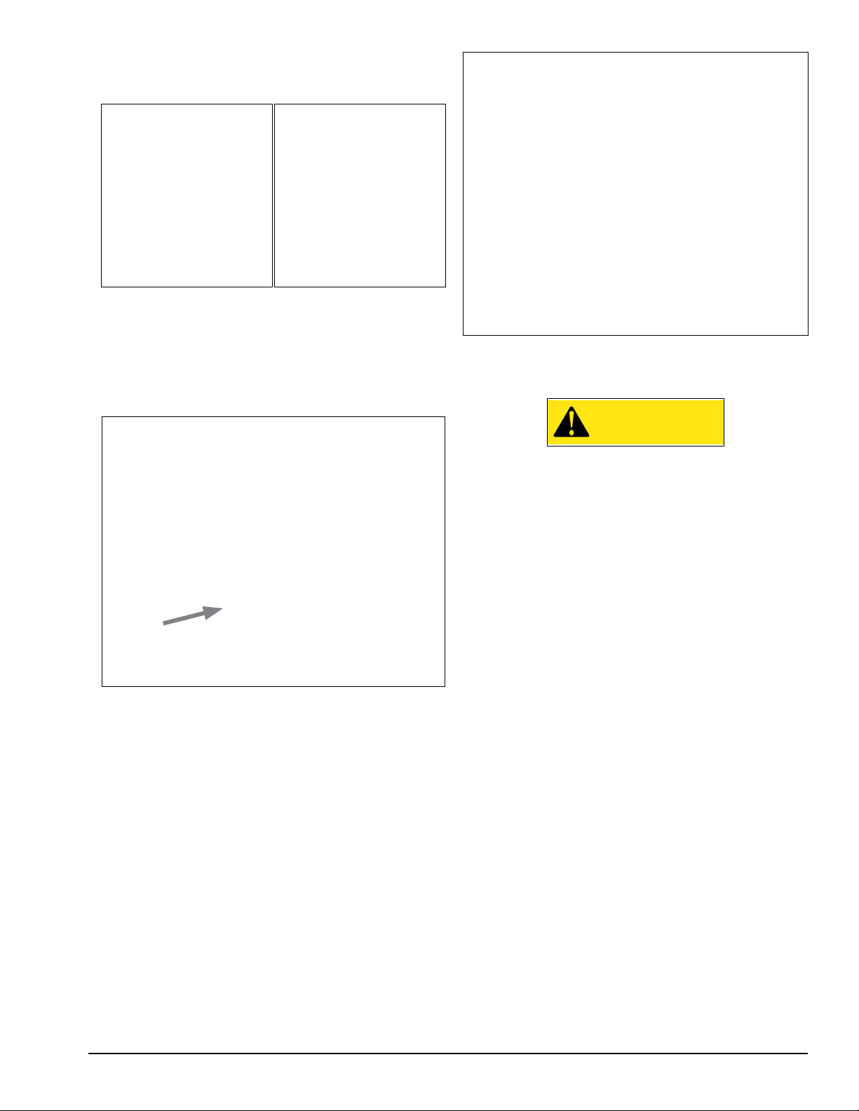
10. Turn wheel in direction of outboard
arrow until this symbol appears:
Note: If an outboard corrective weight is not
required the measurement will read - - -, go
to step 12.
11. Attach outboard corrective weight.
Attach specified weight amount at top-dead-center on
outside flange of wheel (clip 2).
12. Lower hood to respin the tire/wheel
and check balance.
The weight readings should now be - - -.
Figure 1 - Clip-On Weight Location
5. Lower wheel guard to enter W wheel
dimension automatically.
6. With hood lowered; wheel spins and
out of balance values are measured and
displayed.
The corrective weight amount appears on the video
display for inboard and outboard weight locations.
7. Raise hood after tire stops rotating.
Wait for wheel to stop before raising the wheel guard.
Note: Throughout this manual tire dimensions are
referred to as A, W, and D, see figure 2.
Figure 2 - A, W, and D Tire Dimensions
Important: Always read and follow instructions. • 5
Page 10
Principle Operating Parts
A
B
C
D
K
E
H
J
L
G
M
N
O
P
R
A
B
C
D
E
G
H
J
K
L
M
N
0
P
R
Know Your Unit
Compare this illustration with the unit before placing
it into service. Maximum performance and safety will
be obtained only when all persons using the unit are
fully trained in its parts and operation. Each user should
learn the function and location, of all controls.
Prevent accidents and injuries by ensuring the unit is
properly installed, operated and maintained.
H
A
J
B
K
C
D
L
E
G
A - Video Screen
B - Control Panel
C - Plug (Back Of Machine)
D - Connect To Air (Back Of Machine, PL Version
Only)
E - ON/OFF Switch
G - Storage Pegs
H - Hood Guard
J - Hood Sonar - Width Sensor
M
O
P
R
N
K - Weight Tray with Pockets for Weights
L - Offset Arm, Measures A & D of Tire/Wheel
(Shown In Home Position)
M - Lateral Runout Sensor (Optional)
N - Positioning Pedal (Release Pedal On
Pneumatic)
0 - Radial Runout Sensor
P - 40 mm Shaft (Pneumatic Shaft Optional)
R - Laser Locator
Pneumatic
Shaft
6 • Important: Always read and follow instructions.
Page 11
Note: Throughout this manual, wheel weights are
referred to as Clip-on or Tape-A-Weight®. Figure 3
shows an example of each weight.
Clip-on Weight Tape-A-Weight
Figure 3 - Corrective Weight Examples. For Best Results, use
BADA® Brand Wheel Weights.
®
Power Switch
The ON/OFF switch location (figure 4) is on the left
side of the balancer; below the weight tray.
Offset Arm
In Home
Position
Laser
Locator
Figure 5 - Location of Offset Arm (Stored In Home Position)
and Laser Locator
Wheel Guard
CAUTION
Never raise up the wheel guard before the
wheel has come to a stop. Keep hair, loose
clothing, fingers and all parts of body away
from moving parts.
ON/OFF
Power
Switch
Figure 4 - On/Off Switch
Using The Offset Arm
Use the offset arm gauge to automatically measure
the distance from wheel to machine and the wheel
diameter at the point of weight application. Also, use
the offset arm for the correct positioning of weight
application on the inside rim as indicated by the balancer instructions. When not in use or when prompted
by the balancer instructions, store the offset arm in the
home position as shown in figure 5.
Using The Laser Locator
If a hidden weight (Tape-A-Weight®) location is
selected, use the laser locator (figure 5) to point to the
hidden weight location.
If, due to a fault in the machine, the wheel keeps
spinning permanently, switch off the machine at the
master switch or by unplugging the plug from the
power supply. Wait until the wheel stops, or actuate the
positioning pedal before opening the wheel guard.
Positioning Pedal
In the standard version, the pedal controls a mechanical brake which facilitates positioning and holding the
wheel in place for corrective weight application.
In the pneumatic version, the pedal engages/releases
the pneumatic sleeve. The pedal has two positions: the
upper position releases the pneumatic sleeve; the lower
position engages the pneumatic sleeve to mount the
wheel onto the pneumatic shaft.
Auto Wheel Lock Feature (PL Version Only)
Once the assembly is rotated to the weight application
position, it will lock in place to assist in weight placement. Simply apply additional force and the lock will
release to allow movement to the next weight position.
Note: For best performance, choose an outboard
weight position as deep into the rim as wheel allows.
Important: Always read and follow instructions. • 7
Page 12

Control Panel
To enter a function, press the appropriate function key.
Note that the balancer monitor is not a touch screen type
(figure 6).
Figure 6 - Press Control Panel Function Keys
Note: Only press buttons with your fingers. Never use
the weight hammer or other pointed objects to press
buttons.
8 • Important: Always read and follow instructions.
Page 13

Balancer Function Set-up and
Review
Video Screen Flowchart
PASSWORD : + + +
FOR SPECIALIZED PERSONNEL ONLY
ID SCREEN
Important: Always read and follow instructions. • 9
Page 14

Screen-Saver Mode
User Memory
If the machine remains on the initial screen for a
certain amount of time without being used, the system automatically switches to a screen-saver. In most
cases, to reactivate the initial screen, just mount a
wheel, rotate the wheel or press a key to provide the
input to wake the balancer back up.
Home Screen
Buttons enabled:
Use the wheel balancer simultaneously by four different users who, through a simple sequence, can memorize their work condition and call it up when needed.
To enter in a user name access the special functions
screen and select the operator name option.
Buttons enabled:
User
Select a user into current program memory.
Load User
Select to recall a user’s memorized work condition.
Save User
Select to memorize the current user’s work condition.
Note: The dimensions memorized as USER are lost
when the machine is switched off.
Note: The current USER is always displayed in the
measurements and dimensions screens.
Menu
Access the balancer’s main functions screen.
User
Select to access user memory functions.
Start
Press to spin assembly.
10 • Important: Always read and follow instructions.
Page 15

Menu Screen
The menu screen provides you with many possibilities
for accessing programs and presetting the machine
according to your requirements. These settings remain
unaltered even when the machine is switched off.
Buttons enabled:
Menu
Return to previous window
Machine Spins/day - Indicates the number of spins
from the first time the machine is turned on for the day.
When the machine is turned off, this parameter remains
stored until the date changes (a new day).
Daily Weight Statistics - Each horizontal line indicates
the number of clip-on and adhesive weights used to
balance the wheels.
• Tot g (tot oz): indicates the daily weight value of the
clip-on and adhesive weights used to balance the
wheels.
• Tot n: indicates the daily number of clip-on and adhesive weights used to balance the wheels.
Under statistics the following buttons are enabled:
➤ Reset
Resets the daily statistics or resets the total statistics (in this case, a keyword must be entered).
➤ Total
Goes to the total statistics frame containing the
same information as the daily statistics but referring to the time interval between the two dates
displayed.
Stop & Exit
Return to Result screen
Optimization (Match Balance)
Select this mode to access the optimization program.
See Optimization (Match Balance).
Dimensions
Access this screen to view the tire/wheel dimension
measurements. See Setting Wheel Dimensions (DIM).
Statistics
➤ Print
Prints the daily/total statistics (option).
➤ Exit
Return to the previous screen.
Service Adjustments
In order to gain access to the “Reserved Calibrations
and Functions” it is necessary to enter a password.
Any incorrect operation within the functions described
below could impair the operation of the wheel balancing
machine. Unauthorized use will cause cancellation of
the warranty on the machine.
General Set-up
Select this to access the General Set-up screen.
Balancer Set-up
Select this to access the Balancing Set-up screen.
Special Functions
Select this to access the Special Functions screen.
Important: Always read and follow instructions. • 11
Page 16

General Set-up Screen
Acoustic Signal
When ON is selected, the sending of an acoustic signal
(beep) is enabled in the following cases:
• when any push button is pressed.
• when dimensions are acquired in automatic mode.
• when the correct angular position for weight application is reached in the result screen.
• when the correct angular position for weight application is reached in the position repeater screen.
Wheel Guard Open During Spin
The general set-up screen provides you with many
possibilities for presetting the machine according to
your requirements. These settings remain unaltered
even when the machine is switched off.
Buttons enabled:
Menu
Return to previous window
Stop & Exit
Return to Result screen
Language
Access this function to select the language you want
for displaying descriptive and diagnostic messages
regarding machine operation.
Screensave Time
If this function is enabled, the screensaver automatically activates when the machine is not used for a
certain period of time. You disable this function by
setting it to 0 min.
CAUTION
Never raise up the wheel guard before the
wheel has come to a stop. Keep hair, loose
clothing, fingers and all parts of body away
from moving parts.
Select the ON option to enable opening of the guard
(when the motor is off) during a spin. If the guard is
opened when the motor is on, error 5 (guard open) is
displayed. If OFF is selected, an error 5 (guard open) will
always signal when the guard is opened.
Hood Start
Select the ON option to enable the automatic start of
the spin when the guard is closed.
Serial Output
This option enables/disables the sending of the measured out of balance and phase values to serial output
RS232C.
Clock Setting
Use to set the correct date and time. Follow the instructions on screen.
12 • Important: Always read and follow instructions.
Page 17

Balancing Set-up Screen
Runout Options
Under runout options the following buttons are enabled:
➤ Radial Runout Displayed
The radial runout value display on the main screen.
➤ Runout Diagnosis
Enable/disable automatic runout diagnosis screen at
the end of spin.
➤ Runout Measuring Unit
Select whether to display runout values in mm or
inches.
The balancing set-up screen provides you with many
possibilities for presetting the machine according to
your requirements. These settings remain unaltered
even when the machine is switched off.
Buttons enabled:
Menu
Return to previous window
Stop & Exit
Return to Result screen
Display Options
Under display options the following buttons are enabled:
➤ Display Units
Select whether to display the out of balance values
in grams, ounces or both.
➤ Static Imbalance Displayed
Enable/disable Static on Screen™ display. You can
always select the static frame by pressing the button
from the result screen.
➤ Calculation Roundoff
Scroll through to set a weight correction roundoff
value. Typically you would set it around 0.25 ounces
(7 g) for most wheels and around 0.50 ounce (14 g)
for heavy wheels.
➤ Max True Runout Limit
Set a desired tolerance that indicates the limit of
runout allowed on the tire/wheel before it is suitable
to match balance.
➤ Rim Runout Limit
Set a desired tolerance that indicates the limit of
runout allowed on the rim before it is suitable to
match balance.
➤ Correction Runout Limit
Set the minimum correction limit tolerance obtainable below which it is not considered appropriate to
match balance.
Light Truck Mode
The default is OFF. Scroll to set a value of 1", 1.5" or 2".
This is only necessary if a tire/wheel assembly requires
an adjustment to the automatic width measurement
value, where the actual tire width value is greater than
(extends beyond) the actual rim width value.
Offset Arm Locking
Enable/disable distance gauge locking when the correct
distance is reached to apply the adhesive weight to correct the out of balance. To release the offset arm, lower
it to below 10-inch diameter.
➤ Lower Weight Limit
The out of balance threshold below which - - -,
instead of the out of balance value, appears on the
screen at the end of a measurement cycle. Note that
the closer you set the lower limit to 0.13 ounces (4
g) the more respins you will have when attaching a
0.25 ounce (7 g) weight.
Important: Always read and follow instructions. • 13
Page 18

Wheel Locking
Enable/disable wheel locking in the weight correction
position. Operational only on PL version balancer.
The possible options are:
OFF: disabled
ON: enabled
ALUS: enables wheel locking in position for the ALUS
correction mode only.
Laser
Enable/disable laser for adhesive weight positioning.
Note that offset arm locking will not be enabled when
laser is activated.
Mounting Wheel On Shaft
Select the most appropriate mounting method for
the wheel you are balancing. Using the proper method
ensures secure mounting and safe balancer operation,
and prevents damage to the wheel.
On most wheels, the inner side of the wheel hub usually has the most uniform surface for wheel balancing.
Always center the wheel by the most uniform shaped
side of the hub to achieve the most accurate balance.
Regardless of mounting type, on standard units,
always make sure that the wheel is forced firmly against
the shaft faceplate and that the hub nut engages the
threaded shaft for at least four complete turns. To assist
in centering the wheel properly, rotate the wheel and
the shaft while tightening the hub nut.
Special Functions Screen
Buttons enabled:
Owner Address
This information appears on the screensaver.
Operators Name
Enter up to four different machine user names. Follow
the on-screen instructions to complete the customizing.
Machine Self-test
Self-diagnostic screen is provided for easier troubleshooting.
CAUTION
Failure to tighten the hub nut properly may
result in the wheel dismounting, causing
personal injury and property damage.
Standard Back Cone Mounting
Most original equipment and steel wheels can be
mounted properly using this method. The wheel is
centered on a cone from the inner side of the hub.
Shaft Cone
Face Plate
Figure 7 - Standard Back Cone Mounting
1. Select the cone that best fits the center hole in the
wheel. Slide the cone onto the shaft with the large end
towards the faceplate.
2. Lift wheel onto the shaft and center it on the cone.
3. Attach the pressure cup to the hub nut and install
the assembly onto the shaft. Tighten securely.
Note: Use a nylon spacer (no mar ring) to protect
custom wheel finishes.
Protective
Pressure
Cup
Ring
Hub Nut
4. Thread the hub nut onto the shaft, and tighten it
against the wheel. The wheel must be forced firmly
against the faceplate. The hub nut must engage the
threads for at least four full turns.
Note: If the hub nut will not tighten completely, use
the front cone mounting method.
14 • Important: Always read and follow instructions.
Page 19

Standard Front Cone Mounting
A wheel should be centered by the outer side of the
hub only when the inner surface will not provide an
accurate surface to center on.
Shaft
Cone
No-Mar
Ring
Shaft
Face Plate
Figure 8 - Front Cone Mounting
Cone
Hub Nut
1. Select the cone that best fits the center hole in
the wheel.
2. Lift the wheel onto the shaft and slide it back
against the shaft faceplate.
3. Slide the cone onto the shaft and into the center of
the wheel. You will need to lift the tire to seat the cone
in the center hole.
4. Install the hub nut (without pressure cup) onto the
shaft. Tighten it securely against the cone. The hub nut
must engage the threads for at least four full turns.
Note: If the hub nut will not tighten completely
because of a lack of threads, use an additional cone as
a spacer between the mounting cone and the hub nut.
The wheel must be forced firmly against the faceplate.
Alternate Mounting
If the wheel has a protruding outer hub which will not
permit the use of the pressure cup, or the cup will not
permit the hub nut to engage at least four turns of the
shaft, this alternate method should be used.
Face Plate
Figure 9 - Alternate Mounting
Hub Nut
Pneumatic Shaft (PL Version Only)
Use the most appropriate mounting method for the
wheel, but instead of using a hubnut use the pneumatic
sleeve. When the pneumatic sleeve is in place, press
down on the positioning pedal to mount the wheel on
the shaft.
No-Mar
Ring
Faceplate
Cone
Cup
Pneumatic
Sleeve
Rubber Lip
Figure 10 - Pneumatic Mounting
Pressure
Important: Always be sure to remove the wheel
assembly from the pneumatic shaft before disconnecting the air supply from the machine.
1. Select the cone that best fits the center hole in the
wheel. Slide the cone onto the shaft with the large end
towards the faceplate.
2. Lift the wheel onto the shaft and center it on the
cone.
3. Use the small nylon spacer (no-mar ring) or a
centering cone to press against the outer wheel hub.
4. Install the hub nut (without the pressure cup) onto
the shaft. Tighten securely.
Important: Always read and follow instructions. • 15
Page 20

Setting Wheel Dimensions (DIM)
Wheel Data Entry
Before a wheel can be balanced, wheel dimensions
must be entered into the computer.
Definition of Dimensions (DIM)
W = Width
The width of the wheel at the rim flanges, measured
with the calipers or width sonar as shown in figure 17.
D = Diameter
The diameter of the wheel as indicated on the tire.
A = Offset
The distance measured from the balancer (“0” on offset arm) to inner plane of the rim (inner weight location).
1. To automatically enter A & D dimensions, pull the
offset arm out and up against the wheel at the appropriate weight placement location; hold it still and wait for
the deep or the display to change.
Figure 13- Dimensions Screen
Note: When the offset arm is pulled out from home
position, the dimensions screen is automatically
selected.
Figure 11 - W, D, and A Tire Dimensions
Note: Only use calipers provided by the wheel bal-
ancer manufacturer because others may not be the
same.
Note: A thick flange, on some aluminum wheels, can
effect the measured diameter. For example, a 16-inch
rim can have a measured diameter of 15.5-inches.
A2 = Offset
The distance measured from the balancer (“0” on
offset arm) to outer plane of the rim (outer weight location). Used only for adhesive weight location.
D2 = Diameter
The diameter as measured at the A2 weight location.
Used only for adhesive weight location.
Note: If the acoustic signal is enabled, the acquisition
of the dimensions is accompanied by a BEEP.
Note: When the computer acquires the wheel dimen-
sions it is indicated by the correction weight symbol,
which changes from blue to red.
Automatic A & D Measurement Methods:
• For Clip 1 data entry, move the arm from home posi-
tion and place the offset arm up against the wheel
flange in either position 1 or 2, as shown in figure 14.
Wheel Flange Cut
Away - Inboard
Location
Pos 1
Pos A
Figure 14 - Automatic A & D Measurement At Clip 1 Weight
Location
Figure 12 - A2 and D2 Tire Dimensions
16 • Important: Always read and follow instructions.
Page 21

• For A1 data entry, move the arm from home position
and place the offset arm up against the wheel flange
in position A1, as shown in figure 15.
• For A2 data entry, after taking the inboard measurement, move the offset arm to the inner area of the
wheel; up against the rim at the outboard weight
placement location, as shown in figure 15.
Important: The A2 measurement must be at least
2-inches greater than the A1 measurement.
Inboard
Outboard
Dimension screen buttons enabled:
- automatic width measurement
- automatic ALUS wheel measurement
are:
Static / Dynamic
Toggle between Dynamic and Static balancing.
Weight Type Selection
Select either clip or adhesive weight for inboard plane.
A1 A2
Position of Adhesive
Weights
Figure 15 - Automatic A2 & D2 Measurement At Adhesive
Weight Location
2. Return offset arm to home position.
3. Lower the hood guard to enter W wheel data
automatically.
Weight Type Selection
Only for automatic width: select either clip or adhesive
weight for outboard plane.
Dimensions
Select the manual dimension presetting screen.
Exit
Return to Result screen
Stop & Exit
Return to Home screen
Spin Wheel
When hood guard is lowered wheel spins and out of
balances are measured
Note: When manually entering W, use the plastic
calipers provided with the wheel balancer to measure
the wheel width, as shown in figure 17. Enter the W
dimension to match the measured caliper width of the
mounted rim.
FUNCTION ON
INDICATOR: Sonar
“WIDTH”.
Figure 16 - Automatic W Measurement
Note: After wheel data entry, use the key to
select the inboard plane correction type for ALUS.
Figure 17 - Caliper Placement On Wheel
Note: You must manually input wheel dimensions for
any wheel above a 24-inch diameter.
Note: On small diameter wheels, the mounting sur-
face must be a minimum 7-inch diameter.
Important: Always read and follow instructions. • 17
Page 22

Balancing A Wheel
A variety of wheel configurations can be balanced
using this wheel balancer. Read through this section,
it will help in determining which balancing options are
best suited for certain wheel assemblies.
Dynamic Balancing
Choose a dynamic balance to balance a wheel using
two planes for correction. Select the weight option that
best fits the available weight locations on the rim.
Clip-on Weights - The standard default; used for most
passenger tire/wheel assemblies using the most common location for corrective weights. Clip-on weights
are placed on the inner (inboard) and outer (outboard)
rim flanges.
Static Balancing
Choose a static balance to balance a wheel using one
plane for correction. Place the single corrective weight
at top-dead-center (12 o’clock) on either flange, at the
center of the rim channel, placed inward either side, or
split on either sides.
ALUS (Aluminum Wheels) - To balance aluminium
wheels you usually use a self-adhesive weight location
that is positioned differently from the clip-on weight
position(s) used in standard balancing. Be sure to use
the appropriate wheel data entry method since the
balancer calculates out of balance values based on the
wheel dimension measurements (DIM) entered for the
tire/wheel assembly.
Figure 16 - Dynamic Balance Weight Locations
Note: When the machine is switched on, a standard
dynamic balance using clip-on weight locations is the
default setting.
Figure 17 - Static Balance Weight Locations
Note: When in static mode, you only need to input the
DIAMETER wheel measurement.
Important: If you decide to use the rim channel for
corrective weight placement, remember you may need
to adjust the DIAMETER measurement input. Typically
you would make it 2 or 3 inches less than the actual tire/
wheel diameter.
18 • Important: Always read and follow instructions.
Page 23

Attaching Corrective Weights
Measurement Result
After the wheel spins and out of balances are measured and displayed, the corrective weight amount
appears on the video display for inboard and outboard
weight locations. Arrows appear that are useful for positioning the corrective weight at the application point.
If the out-of-balance is less than the chosen threshold
value, - - - appears instead of the out-of-balance value
to indicate, on that particular side, that the wheel is in
tolerance.
Measurement Result Screen Options
The following buttons are enabled:
Roundoff
Press to display the residual out of balance, with an
accuracy of 0.1-ounce (0.5 g).
/ / Correction Mode
After performing an automatic entry of wheel dimensions, select to place the correction weights as required.
Figure 18 - Measurement Result Screen
Laser OFF: after positioning and locking the wheel,
apply the weight vertically at 12 o’clock (top-deadcenter).
The symbol is shown on the screen.
Laser ON: apply the clip-on weights at 12 o’clock. If
using adhesive weights, when the correction position is
reached, the laser turns on indicating the point to apply
the adhesive weight.
The symbol
Note: If the acoustic signal is enabled, a BEEP will
signal that the wheel is in position for corrective weight
placement.
Note: If the wheel locking feature is enabled (see
MENU), the wheel is automatically held in place for
corrective weight placement.
is shown on the screen.
Figure 19 - Weight Placement Screen
To display static out of balance, press the button
on the measurement screen (the inner side diameter is
always considered).
Note: If, when an automatic measurement is taken for
both planes, the difference between the inner and outer
diameters is greater than or equal to 2 inches, the system sets the inboard side corrective weight. To modify
this presetting, press the button. The outboard
side may only be “adhesive”.
Note: When the mode is changed, the out of balance
values are recalculated automatically on the basis of the
previous spin. Simultaneous display of the Static out
of balance always preset can be enabled through the
special function in Set-up (STATIC OUT OF BALANCE
DISPLAYED).
Important: Always read and follow instructions. • 19
Page 24

Runout
Runout result screen.
Behind Spokes
Enable split function of out of balance (see Behind
Spokes).
Indicate Exact Corrective Weight Position
If laser disabled, indicates and locks arm when in
correct horizontal plane (see Indicate Exact Corrective
Weight Position).
Special Functions
Selection of special functions.
Balancing Spin
Behind Spoke
“Splitting” weight is used to hide any adhesive weights
behind the rim spokes.
Lower hood, then spin wheel to check balance.
Stop & Exit
Return to Home screen
Figure 20 - Behind Spoke Screen
Press button
LASER OFF: to split the out of balance detected in
two different positions, proceed as follows:
1. Position static out of balance or ALUS external side
in the correction position and press button :
2. Select a spoke close to the 12 o’clock position to
be corrected, move it into the 12 o’clock position and
press button .
3. Turn the wheel in the rotation direction indicated on
the out of balance display, bringing the second spoke to
the 12 o’clock position and press button .
Turn the wheel in direction of rotation.
Turn the wheel in reverse direction of rotation.
4. At this stage, the screen shows the graphic display
of the correction spokes with the relative weight of the
out of balance detected.
5. Position the spokes indicated on screen in the 12
o’clock position and correct with the value displayed.
20 • Important: Always read and follow instructions.
Page 25

LASER ON: to split the out of balance measured in
two different positions, proceed as follows:
Position the static out of balance or outboard adhesive
weight in the correction position and press button
:
1. Turn the wheel and press the button when
the laser points to the spoke where the correction is to
be made.
2. Release the button.
3. Turn the wheel in the direction indicated on the dis-
play until the second spoke is in the position indicated
by the laser and press the
button.
4. At this point, two indications are shown on the
screen to position the spokes for the out of balance
correction.
5. Move the spokes indicated to the correction position and correct according to the value displayed.
Important: Always follow the information provided by
the wheel to optimize correction.
Note: When SPLIT is enabled, the icon appears
on the left of the screen.
Indicate Exact Corrective Weight Position
It is recommended that you always use this function
to correct an out of balance using adhesive weights.
Remember to thoroughly clean the application areas.
Figure 21 - Indicate Exact Corrective Weight Position Screen
LASER OFF: press button on results screen.
Pull out the arm to position 1 as shown in figure 14
page 16:
1. Place a Tape-A-Weight™ onto arm.
2. Rotate assembly until the correction position is
reached, indicated by:
3. Pull arm out until aligns with and
the arm locks into position.
4. Rotate the arm to the correction position and apply
the Tape-A-Weight™ onto the wheel.
Note: When the acoustic signal is enabled, reaching a
fixed arrow is accompanied by a BEEP.
FI
FE
Important: Always read and follow instructions. • 21
Page 26

Match Balance (Optimization)
WARNING
Match Balance involves the loosening of
tire beads and the inflation of a tire. Training
is necessary in tire changer operation and
understanding the dangers involved during bead seating and tire inflation before
attempting this stage of the Match Balance
procedure. Read the operators manual supplied with the tire changer and consult a
supervisor.
Match Balance (Optimization)
The symbol is displayed automatically for static
out of balance exceeding 30 grams (1.1 oz.)
Use the Match Balance (Tire/Rim Weight Optimization) program to determine the best mating of tire and
rim that will result in the least amount of total out of
balance of the assembly. It requires two spins and two
rotations of the tire on the rim. Match Balance may be
needed when:
Important: A high out of balance may indicate the
improper mounting of the assembly on the balancer, or
a rim that is out of round or misformed, or a tire with a
bubble or other problem. If the out of balance is excessive, it may be prudent to replace the rim, the tire, or
both. If either is replaced, do not continue with Match
Balance. Balance the new tire and rim and evaluate the
readings.
If you choose to use Match Balance to correct for a
condition, such as a large static out of balance, then
follow the on-screen instructions for the MATCH BALANCE procedure as outlined in the following steps.
Note: Use this procedure only after the wheel has
spun and the corrective weight amount is displayed.
Note: Presetting of tolerance on the machine. There is
no general rule concerning acceptability of a Max True
Runout Limit (see Balancing Set-up) value. As a first
approximation we consider it correct to use a threshold
of 1 to 1.5 mm.
The much enlarged figures show the outer tire surface
and axis of wheel rotation.
A B
• The customer complains of ride problems.
• The balancer calculates a high out of balance.
• The balancer calls for Total Static weights in excess
of 3 ounces (85 grams) on passenger car tires.
Having performed a balancing spin:
Press + and follow the on-screen
instructions.
Figure 24 - Runout Measurements
Fig. A - shows measurement of the total Peak-to-Peak
runout defined as maximum radial deviation of the tire
surface.
Fig. B - shows measurement of the runout of the
1st harmonic, i.e. the eccentricity of that circle which
“recopies” the tire shape, by averaging the local deviations of the tire from the round shape.
Obviously the P.P. measurement is normally greater
than that of the 1st harmonic. Tire manufacturers normally supply two different tolerances for the two eccentricities. The radial and lateral runout measurements
are automatically carried out after the out of balance
measurement without having to go into particular procedures. Remember to position the sonar sensors in
front of the surface to be measured before pressing the
button.
Figure 23 - Optimization
The maximum limit of the first harmonic can be
set (MAX. TRUE RUNOUT LIMIT). When this limit is
exceeded, the wheel balancer displays a warning and
diagnostic frame indicating an eccentricity condition
that needs to be corrected.
22 • Important: Always read and follow instructions.
Page 27

Figure 25 - Runout Diagnosis Screen
The following buttons are enabled:
Graphics
To display the graphs of the runout program.
Match Balance
To go into the Match Balance procedure.
Result Screen
To go to the result screen (the symbol above the button
is displayed in yellow to indicate an excessive
first harmonic eccentricity value).
If the first harmonic eccentricity is within the permitted
limit, the graphs can in any case be displayed by press-
ing the buttons
/ from the result screen:
Figure 26 - Radial eccentricity measurement graph:
Figure 27 - Radial and lateral eccentricity measurement graph.
BLUE GRAPH: represents the peak/peak eccentricity
whose actual value is displayed and updated by turning
the wheel in correspondence to the word “Cursor”.
RED GRAPH: represents the first harmonic eccentricity.
For a wheel in optimal conditions, this graph must come
close to a straight line.
Under result screen the following buttons are enabled:
➤ Match Bal.
To go to rim runout measurement.
➤ Print
To print the runout values measured (option).
➤ Exit
Return to the previous screen.
Important: Always read and follow instructions. • 23
Page 28

Sonar LR Instruction
In order to obtain the correct lateral eccentricity values, the sonar cone must be positioned inside the tire
shoulder. The function of the LED is to make it easier
to position the sonar correctly, but always bear in mind
that it does not indicate the focus of the pad as it is
situated 30 mm further down.
mm
30
8°
4. Press the button and slowly turn the wheel
by hand, keeping a constant pressure on the arm until
the following frame appears:
FRONT VIEW
Figure 28 - Sonar Placement
LATERAL VIEW
The rim eccentricity measurement is important in
order to try and reduce the total eccentricity of the
wheel simply by turning the tire on the rim.
1. Press the button from the eccentricity
graph display frame
2. Hold the arm as shown in figure 29 in such a way
that it does not turn during the measurement
Figure 31 - Graph
The graph simultaneously shows the total eccentricity,
the rim and the tire values. Before turning the tire on
the rim, check if the POSSIBLE REDUCTION indicated
on-screen is sufficient to bring the wheel eccentricity
within tolerance. It is possible to set the minimum correction limit below which it is never considered appropriate to intervene (CORRECTION RUNOUT LIMIT), and
the maximum first harmonic eccentricity limit of the rim
below which it is considered of little use to turn the tire
on the rim (MAX. TRUE RUNOUT LIMIT).
The following buttons are enabled:
➤ Print
To print the runout values measured (option).
Figure 29 - Hold Arm As Shown
3. Rest the round part of the arm inside the rim as
➤ Exit
Return to the previous screen.
shown in figure 30.
Figure 30 - Rest Round Part Of Arm On Rim As Shown
24 • Important: Always read and follow instructions.
Page 29

Calibration Program
Diagnostic Procedures
In order to gain access to the “Reserved Calibrations
and functions” it is necessary to enter a password.
Any incorrect operation within the functions described
below could impair the operation of the wheel balancing
machine. Unauthorized use will cause cancellation of
the warranty on the machine.
Arm Calibration
Select the gauge to be calibrated and follow the onscreen instructions.
In width gauge calibration, the dimension needs to be
set:
A - GAUGE “ZERO” DISTANCE
SONAR “ZERO” DISTANCE
Figure 32 - Set Dimension
Machine Calibration
For machine calibration, proceed as follows:
1. Mount an average size wheel with steel rim. Es.:
6" x 15" (± 1")
2. Preset the wheel dimensions with GREAT CARE.
3. Follow the on-screen instructions.
Note: You can change the calibration weight from 40
to 100 g (1.40 to 4.00 oz)
After Balance Vibration Problems
If vibration is still present after balancing the wheels
and driving the vehicle on smooth pavement, remove
the wheels and recheck the balance. If a wheel is out
of balance the cause maybe:
• Wheel was not mounted/centered correctly on the
balancer.
• A weight has come off the wheel (possibly the
wrong clip style). Remove the other weights from
the wheel and rebalance.
• Foreign material inside the tire. Remove the tire
from the wheel, remove the foreign material, and
remount. Remove wheel weights and rebalance the
wheel.
• Stones or other foreign objects caught in the tire
tread or rim. Remove the objects. Check and rebalance if needed.
If the balancer still indicates the wheels are balanced
to within 0.01 ounces on both inner and outer displays,
the problem is not in the balance of the wheels. Check
the following possible sources of vibration:
• Tire pressure. Bring all tires up to the recommended
PSI.
• Radial or lateral runout in the tire or wheel. Replace
the damaged part.
• Out of balance in wheel covers or trim rings.
Remove the wheel covers or trim rings and test
drive. If the vibration is gone, remove the shaft and
use an appropriate adapter to mount the wheel to
the balancer. Balance the wheel with the wheel
cover or trim ring attached to the wheel.
• Incorrectly mounted tire and wheel. Remount correctly.
• Damaged wheel bolt holes. Replace wheel.
• Worn universal joints. Replace as required.
• Drive shaft out of balance or damaged. Balance,
repair, or replace.
• Out of balance in brake rotor(s) or drum(s).
• Suspension out of alignment. Align the vehicle and
replace any damaged or worn parts.
Important: Always read and follow instructions. • 25
Page 30

Troubleshooting
The machine recognizes a number of incorrect
operations and displays this as an error message. Listed
ERROR CAUSE REMEDY
Black
Err. 1
Err. 2
Err. 3
Err. 4
Err. 5
Err. 7, 8 or
10
Err. 9
Err. 11
Err. 14, 15,
16, 17, 18
or 19
Err. 22
Err. 30
Err. 40, 41,
42 or 43
Err. 45, 46,
47 or 48
Err. 50, 51,
52 or 53
The wheel balancer does not switch
on.
No rotation signal. 1. Check in self-diagnostics that the encoder functions properly.
Speed too low during detection.
During unbalance measurement
rotation, wheel speed is less than 42
rpm.
Out of balance too high. 1. Verify wheel dimension settings.
Rotation in opposite direction.
After pressing [START], the wheel
starts turning in the opposite direction (anticlockwise).
Guard open
The [START] pushbutton was pressed
without first closing the guard.
NOVRAM parameter read error 1. Repeat machine calibration
NOVRAM parameter write error. Replace the computer board.
Speed too high error.
During out of balance measurement
rotation, wheel speed is more than
270 rpm.
Out of balance measurement error. 1. Check in self-diagnostics that the encoder functions properly
Maximum number of spins possible
for the out of balance measurement
has been exceeded.
Clock error Replace the computer board.
Eccentricity graph plotting procedure
error.
Eccentricity graph value display readout error.
Eccentricity graph current value cursor plotting procedure error.
1. Verify correct connection to the mains.
2. Verify and eventually replace the fuses on the power card.
3. Verify monitor function.
4. Replace the computer board.
2. Replace the phase pick-up board.
3. Replace the computer board.
1. Make sure a vehicle wheel is mounted properly on wheel balancer.
2. Check in self-diagnostics that the encoder functions properly.
3. Disconnect the piezo connectors from the board and do a spin (if no
error is detected, replace the piezo sensors).
4. Replace the computer board.
2. Check detection unit connections.
3. Perform machine calibration.
4. Mount a wheel with more or less known out of balance (less than
100 grammes) and verify the response of the machine.
5. Replace the computer board.
1. Check in self-diagnostics that the encoder functions properly
2. Check the bearing/spring of the phase generator
1. Reset the error by pressing pushbutton [7]=End.
2. Close the guard.
3. Verify the function of the protection uSwitch.
4. Press the [START] pushbutton.
2. Shut down the machine.
3. Wait for a minimum time of ~ 1 Min.
4. Re-start the machine and verify correct operation.
5. Replace the computer board.
1. Check if there is any damage or dirt on the timing disc.
2. Check in self-diagnostics that the encoder functions properly.
3. Replace the computer board.
2. Check detection unit connections.
3. Verify machine earth/ground connection.
4. Mount a wheel with more or less known out of balance (less than
100 grammes) and verify the response of the machine.
5. Replace the computer board.
1. Check that a vehicle wheel has been mounted properly on the wheel
balancer.
2. Check in self-diagnostics that the encoder functions properly.
3. Replace the computer board.
erform a new eccentricity measurement.
P
Perform a new eccentricity measurement.
Perform a new eccentricity measurement.
below are faults that the user can remedy if the cause
is found to be among those indicated. Any other defect
or malfunction will require the attention of a qualified
technician: Contact your nearest COATS
®
service center.
26 • Important: Always read and follow instructions.
Page 31

ERROR CAUSE REMEDY
Err.54
Err.55
Err.56
Err.57
Err.58
Err.59
Err.65
Err.66
Err.70
Out of
balance
incorrect
with back
centering
cone
Sonar readout error.
Sonar value readout impossible.
Sonar readout error.
Sonar values are insuffi cient for correct measurement of eccentricity.
Lateral Sonar readout error.
Lateral Sonar value readout impossible.
Lateral Sonar readout error.
Lateral Sonar values are insuffi cient
for correct measurement of lateral
eccentricity.
Radial and lateral Sonar readout error.
Radial and lateral Sonar value readout
impossible.
Radial and lateral Sonar readout error.
Lateral and radial Sonar values are
insufficient for correct measurement
of radial and lateral eccentricity.
Printer timeout 1. Check that a printer is present.
Printer buffer error 1. Reset the printer.
Error regarding ADC 16 bit readings 1. Check correct connection cable for distance and diameter gauge
Wheel slipping on the adapter because the BP system is at the end of
travel or because of incorrect fitting
of the tire tie-rod.
1. Position the eccentricity measurement sonar correctly before performing the measurement.
2. Check eccentricity sonar connections.
3. Check the power supplies on the power board.
4. Replace the eccentricity measurement sonar.
5. Make sure that the wheel does not halt before completing at least
4/5 revolutions after the fi rst braking impulse.
6. Verify belt tautness.
7. Replace the computer board.
1. Position the eccentricity measurement sonar correctly before performing the measurement.
2. Make sure that the wheel does not halt before completing at least
4/5 revolutions after the fi rst braking impulse.
3. Verify belt tautness.
4. Mount a wheel of medium dimensions (14”x5 ¾”) and perform an
eccentricity measurement . If in these conditions error 55 no longer
occurs, this means that the wheel inertia causing the problem is
such as to half the wheel before having acquired the minimum number of values necessary for reliable eccentricity measurement.
1. Position the eccentricity measurement lateral sonar correctly before
performing the measurement.
2. Check eccentricity lateral sonar connections.
3. Check the power supplies on the power board.
4. Replace the eccentricity lateral sonar.
5. Make sure that the wheel does not stop before completing at least
4/5 revolutions after the fi rst braking impulse.
6. Verify belt tautness.
7. Replace the computer board.
1. Position the eccentricity lateral sonar correctly before performing the
measurement.
2. Make sure that the wheel does not stop before completing at least
4/5 revolutions after the fi rst braking impulse.
3. Verify belt tautness.
4. Mount a wheel of medium dimensions (14”x5 ¾”) and perform an
eccentricity measurement. If in these conditions error 57 no longer
occurs, this means that the wheel inertia causing the problem is
such as to half the wheel before having acquired the minimum number of values necessary for reliable lateral eccentricity measurement.
1. Check points Err. 54
2. Check points Err. 56
1. Check points Err. 55
2. Check points Err. 57
2. Check the code of the processor card.
3. Check the printer <-> processor card connection.
4. Run the printer test function.
2. Repeat the print function.
(CN5/CN4).
2. Switch off the machine, wait about 30 seconds and switch on again .
3. Replace the PC board.
Mount the wheel in vertical position and push the sleeve up against
the wheel. If necessary, repeat locking/unlocking/locking and perform
the procedure again.
Important: Always read and follow instructions. • 27
Page 32

Maintenance Instructions
The balancer requires only minor maintenance to keep
the unit operating properly.
1. Keep the display clean and clear. Use a damp cloth.
Do not use cleaners or solvents which leave oily or filmy
residues behind.
2. Keep the adapters, cones, faceplate, threaded
shaft, pressure cup, and hub nut clean. Grease and dirt
buildup will cause inaccurate balancing and premature
wear. Clean these items at least once a day with a
vaporizing solvent.
3. Clean weight tray and any accessory posts, pegs,
or storage shelves with a vaporizing solvent. Weights
stored in a dirty tray may pick up grease and dirt which
may keep them from securely attaching to the wheel.
4. Keep the area around and under the balancer
clear. Remove any tools or other items that are leaning
against the balancer. Remove any items that may cause
the balancer to not sit level. Be particularly cautious of
new or used wheel weights on the floor, as they may
cause personal injury due to falls.
5. Use only COATS
other manufacturers may not fit or function properly,
and may damage the balancer.
®
accessories. Accessories from
WARNING
Use common sense, this is an electrical
device. Exposing the balancer to water,
either by hose or bucket, or by exposure
to rain or snow, may cause risk of shock
or electrocution to operator or bystanders.
Place, store, and operate the balancer only
in a dry, sheltered location.
CAUTION
Do not hose down with water or bucket
wash the balancer. Extensive damage to
the balancer will result. Sensitive electronic
components, wiring harnesses, and other
devices housed in the balancer are not
intended to be exposed to water.
Important: Always be sure to remove the wheel
assembly from the pneumatic shaft before disconnecting the air supply from the machine.
28 • Important: Always read and follow instructions.
Page 33

Glossary
ALUS -Alloy wheel mode that typically requires the
use of one or two adhesive weights for correction.
Balancer Flange – Disk that mates with the disk of
the wheel mounted to the balancer. The flange also
serves to keep the wheel perfectly perpendicular to its
axis of rotation.
Balancing Cycle – Sequence of operations performed
by the user and the machine, beginning from the start
of the wheel spin to the time that the wheel is braked to
a standstill after the out of balance signals are acquired
and the relative values calculated.
Centering – Procedure for positioning the wheel on
the spindle shaft with the aim of ensuring that the
rotational axis of the wheel is aligned with the center
of the shaft.
Centering Flange (accessory) – Device serving to
support and center the wheel. Also keeps the wheel
perfectly perpendicular to its axis of rotation. The centering flange is mounted to the balancer shaft by means
of its center hole.
Cone – Conical components with center hole. When
inserted on the spin shaft, serves to center wheels with
centre holes whose diameter is between maximum and
minimum values.
Dynamic Balancing – Operation in which out of bal-
ance is corrected by the application of two weights, one
on each side of the wheel.
Self-calibration – A procedure whereby suitable cor-
rection coefficients are calculated by starting from
known operating conditions. Self-calibration improves
the measurement precision of the machine by correcting, within limits, calculation errors that may arise due
to alteration of the machine’s characteristic over the
course of time.
Spin – Procedure starting from the action that causes
the wheel to rotate and the successive free rotation of
the wheel.
Hubnut – Device for clamping the wheel to the bal-
ancer. The hubnut features elements for engaging to the
threaded hub and lateral pins that are used to tighten it.
Static Balancing – In static balancing only the static
component of out of balance is corrected. This is
achieved by fitting a single weight, usually at the
center of the rim channel. The accuracy of this system
increases as the width of the wheel decreases.
Threaded Hub – Threaded part of the shaft that is
engaged with the hubnut to clamp the wheel. This
component is supplied disassembled from the machine.
Out of balance – Non-uniform distribution of the
wheel mass that results in the generation of centrifugal
force during rotation.
Important: Always read and follow instructions. • 29
Page 34

85607587 00 07/2011 © Copyright 2011 Hennessy Industries and COATS® All Rights Reserved. Printed in USA
 Loading...