

Page 1
®
Pit Tire Changer
For servicing NASCAR type tire/wheel assemblies
(with and without liners)
1601 J. P. Hennessy Drive, LaVergne, TN USA 37086-3565 615/641-7533 800/688-6359 Manual Part No.: 85000681 00
HENNESSY INDUSTRIES INC. Manufacturer of AMMCO
®
, COATS®and BADA®Automotive Service Equipment and Tools. Revision: 10/07
See
Operating
Instructions
on page 3.
Operating Instructions
with Parts Identification
READ these instructions before placing unit in
service KEEP these and other materials delivered
with the unit in a binder near the machine for
ease of reference by supervisors and operators.
Page 2

ii • Important: Always read and follow the operating instructions.
Table of Contents
Safety Instructions . . . . . . . . . . . . . . . . . . . . .iii
Owner’s Responsibility . . . . . . . . . . . . . . . . . . . . . .iii
Operator Protective Equipment . . . . . . . . . . . . . . . .iii
Definitions of Hazard Levels . . . . . . . . . . . . . . . . . .iii
Safety Notices and Decals . . . . . . . . . . . . . . . . . . .iv
Remember R.I.M. . . . . . . . . . . . . . . . . . . . . . . . . . .iv
Principle Operating Parts . . . . . . . . . . . . . . . . .1
Know Your Unit . . . . . . . . . . . . . . . . . . . . . . . . . . . .1
Operating Instructions . . . . . . . . . . . . . . . .2 - 6
Demounting a NASCAR Type Tire with
Liner using a COATS PIT Tire Changer . . . . . . . .2 - 4
Mounting a NASCAR Type Tire with
Liner using a COATS PIT Tire Changer . . . . . . . .5 - 6
Inflation . . . . . . . . . . . . . . . . . . . . . . . . . . . . . . .7
Mismatched Tires and Wheels . . . . . . . . . . . .8
Stages of Inflation . . . . . . . . . . . . . . . . . .9 - 10
Bead Sealing . . . . . . . . . . . . . . . . . . . . . . . . . . . . .10
Bead Seating . . . . . . . . . . . . . . . . . . . . . . . . . . . . .10
Inflation . . . . . . . . . . . . . . . . . . . . . . . . . . . . . .10 - 11
Maintenance Instructions . . . . . . . . . . .11 - 12
Separator/Lubricator Maintenance . . . . . . . . . . . . .12
Air Source . . . . . . . . . . . . . . . . . . . . . . . . . . . . . . .12
Electrical Source . . . . . . . . . . . . . . . . . . . . . . . . . .12
Parts Identification . . . . . . . . . . . . . . . . .13 - 23
Chassis Assembly . . . . . . . . . . . . . . . . . . . . . . . . .13
Foot Pedal Assembly . . . . . . . . . . . . . . . . . . . . . . .14
Table Top Assembly . . . . . . . . . . . . . . . . . . . . . . . .15
Shaft Housing Assembly . . . . . . . . . . . . . . . . . . . .16
Horizontal Slide Assembly . . . . . . . . . . . . . . . . . . .17
Pressure & Inflation Bracket System . . . . . . .18 - 19
Robo Arm Assembly . . . . . . . . . . . . . . . . . . . . . . .20
Auxiliary Arm Assembly . . . . . . . . . . . . . . . . . . . . .21
Cylinder Assembly . . . . . . . . . . . . . . . . . . . . . . . . .22
Valve Assemblies . . . . . . . . . . . . . . . . . . . . . . . . . .23
Wiring Diagram . . . . . . . . . . . . . . . . . . . . . . . . . . .23
NOTICE
Read entire manual before assembling,
installing, operating, or servicing this
equipment.
Page 3
Important: Always read and follow the operating instructions. • iii
Safety Instructions
Owner’s Responsibility
To maintain machine and user safety, the responsibility of the owner is to read and follow these instructions:
• Follow all installation instructions.
• Make sure installation conforms to all
applicable Local, State, and Federal Codes,
Rules, and Regulations; such as State and
Federal OSHA Regulations and Electrical
Codes.
• Carefully check the unit for correct initial
function.
• Read and follow the safety instructions.
Keep them readily available for machine operators.
• Make certain all operators are properly
trained, know how to safely and correctly operate the unit, and are properly supervised.
• Allow unit operation only with all parts in
place and operating safely.
• Carefully inspect the unit on a regular
basis and perform all maintenance as required.
• Service and maintain the unit only with
authorized or approved replacement parts.
• Keep all instructions permanently with the
unit and all decals/labels/notices on the unit
clean and visible.
• Do not override safety features.
Operator Protective Equipment
Personal protective equipment helps make tire servicing safer. However, equipment does not take the
place of safe operating practices. Always wear durable
work clothing during tire service activity. Loose fitting
clothing should be avoided. Tight fitting leather gloves
are recommended to protect operator’s hands when
handling worn tires and wheels. Sturdy leather work
shoes with steel toes and oil resistant soles should be
used by tire service personnel to help prevent injury in
typical shop activities. Eye protection is essential during tire service activity. Safety glasses with side
shields, goggles, or face shields are acceptable. Back
belts provide support during lifting activities and are
also helpful in providing operator protection.
Consideration should also be given to the use of hearing protection if tire service activity is performed in an
enclosed area, or if noise levels are high.
Definitions of Hazard Levels
Identify the hazard levels used in this manual with the
following definitions and signal words:
DANGER
Watch for this symbol:
It Means: Immediate hazards, which will result in
severe personal injury or death.
WARNING
Watch for this symbol:
It Means: Hazards or unsafe practices, which could
result in severe personal injury or death.
CAUTION
Watch for this symbol:
It Means: Hazards or unsafe practices, which may
result in minor personal injury or product or property
damage.
Watch for this symbol! It means BE ALERT! Your
safety, or the safety of others, is involved!
DANGER
WARNING
CAUTION
Page 4
iv • Important: Always read and follow the operating instructions.
Safety Notices and Decals
Failure to follow danger, warning, and caution instructions may lead to serious personal injury or death to operator or
bystander or damage to property. Do not
operate this machine until you read and
understand all the dangers, warnings and
cautions in this manual. For additional
copies of either, or further information, contact:
Hennessy Industries, Inc.
1601 J.P. Hennessy Drive
LaVergne, TN 37086-3565
(615) 641-7533 or (800) 688-6359
www.ammcoats.com
For additional information contact:
Rubber Manufacturers Association
1400 K Street N. W.
Washington, DC 20005
(202) 682-4800
Tire Guides, Inc.
The Tire Information Center
1101-6 S o u t h Rogers Circle
Boca Raton, FL 33487-2795
(561) 997-9229
www.tireguides.com
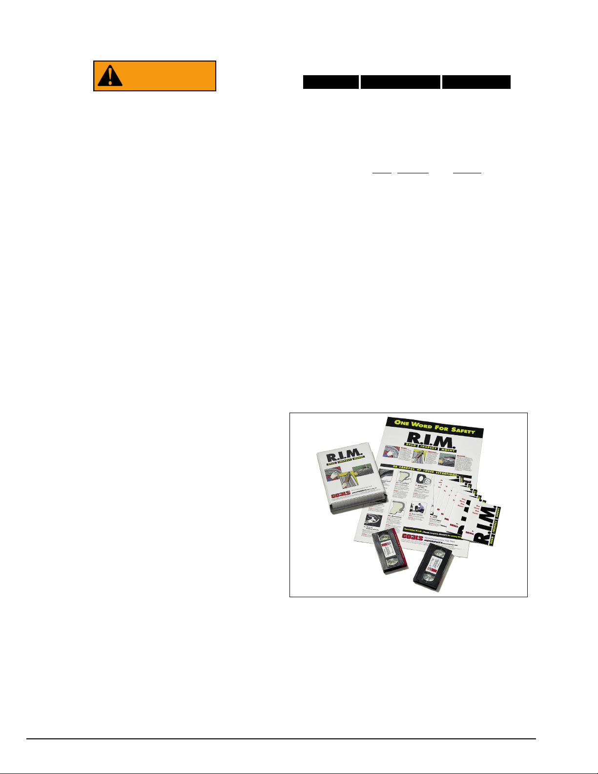
Remember R.I.M.
Three Simple Steps To Help Keep Shops Safe
R.I.M. is a training program developed by Hennessy
Industries to help keep tire technicians safe. By following the basic principles of R.I.M., technicians can avoid
situations that can cause catastrophic accidents like
tire explosions.
R.I.M. stands for read, inspect, and mount:
Read the tire size on a new tire before mounting to
make sure it is the proper size for the wheel.
Inspect the wheel for cracks, rust, and or other damage that could cause an unsafe situation.
Mount the tire safely, making sure not to put any part
of your body over the tire during inflation.
The most serious of possible accidents is a tire explosion. This is often caused by a tire/rim mismatch.
If a tire explodes on a tire changer, pressure causes it
to fly straight up at tremendous speed. If a technician
is standing over the tire, he can be seriously injured or
killed.
Hennessy’s R.I.M. program allows the technician to
avoid situations that can cause tire explosions and
other accidents. The full program, including training
videos, brochures, posters, and other materials, is
available from Coats distributors nationwide.
For more details, contact your Coats distributor or e-mail us.
WARNING
READ
INSPECT MOUNT
Page 5
Important: Always read and follow the operating instructions. • 1
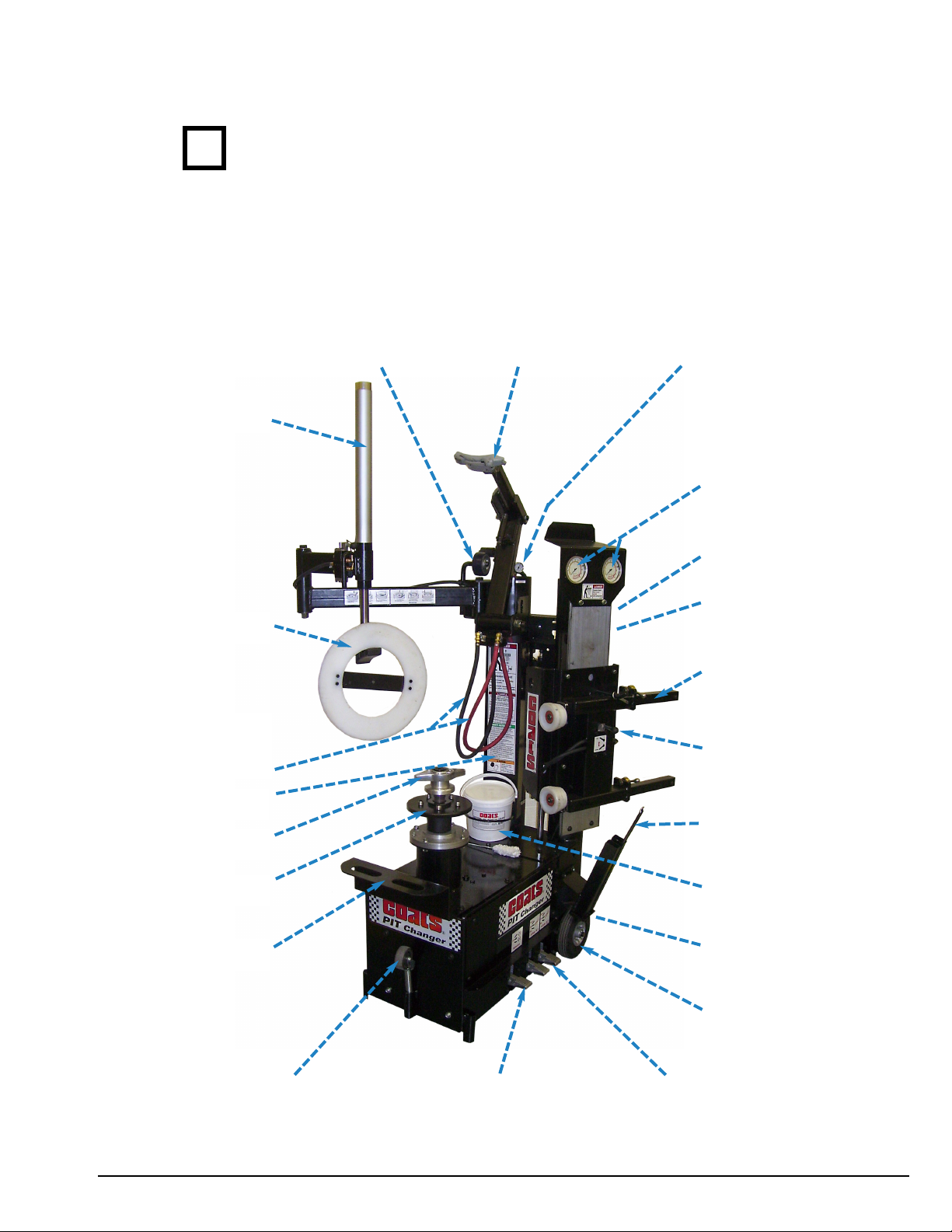
Principal Operating Parts
Know Your Unit
Compare this illustration with the unit before placing it
into service. Maximum performance and safety will be
obtained only when all persons using the unit are fully
trained in its parts and operation. Each user should learn
the function and location, of all controls.
Prevent accidents and injuries by ensuring the unit is
properly installed, operated and maintained.
Do It Now!
Now is a good time
to fill out the Owner’s
Registry Card.
Duckhead® Detent
System
Robo Arm &
Control
Twin Inflation
Hoses & Clip-on
Chucks
Protector Ring
Safety Decal
Hold Down Nut
Wheel Face/Plate
Tire Rim Shelf
Caster Wheel &
Storage
Floating Duckhead
System - with Gray
Duckhead
Air Accumulator
Gauges & Safety
Val ve s
Twin Inflation Gauges
Dolly Handle
Filter/Lubricator
Upper & Lower
Powered Roller
System with Lock &
Pin
Power Roller Actuator
Val ve
Dolly Wheels
110 VAC Electrical
Cord
Paste Lube, Holder, &
Paste Mop
Lift Lever & Storage
Tube
Face Plate Rotation
Twin Inflation & Bleed
Val ve s
✓
Page 6
2 • Important: Always read and follow the operating instructions.
Operating Instructions
Demounting a NASCAR Type Tire with
Liner using a COATS PIT Tire Changer
Following are the steps:
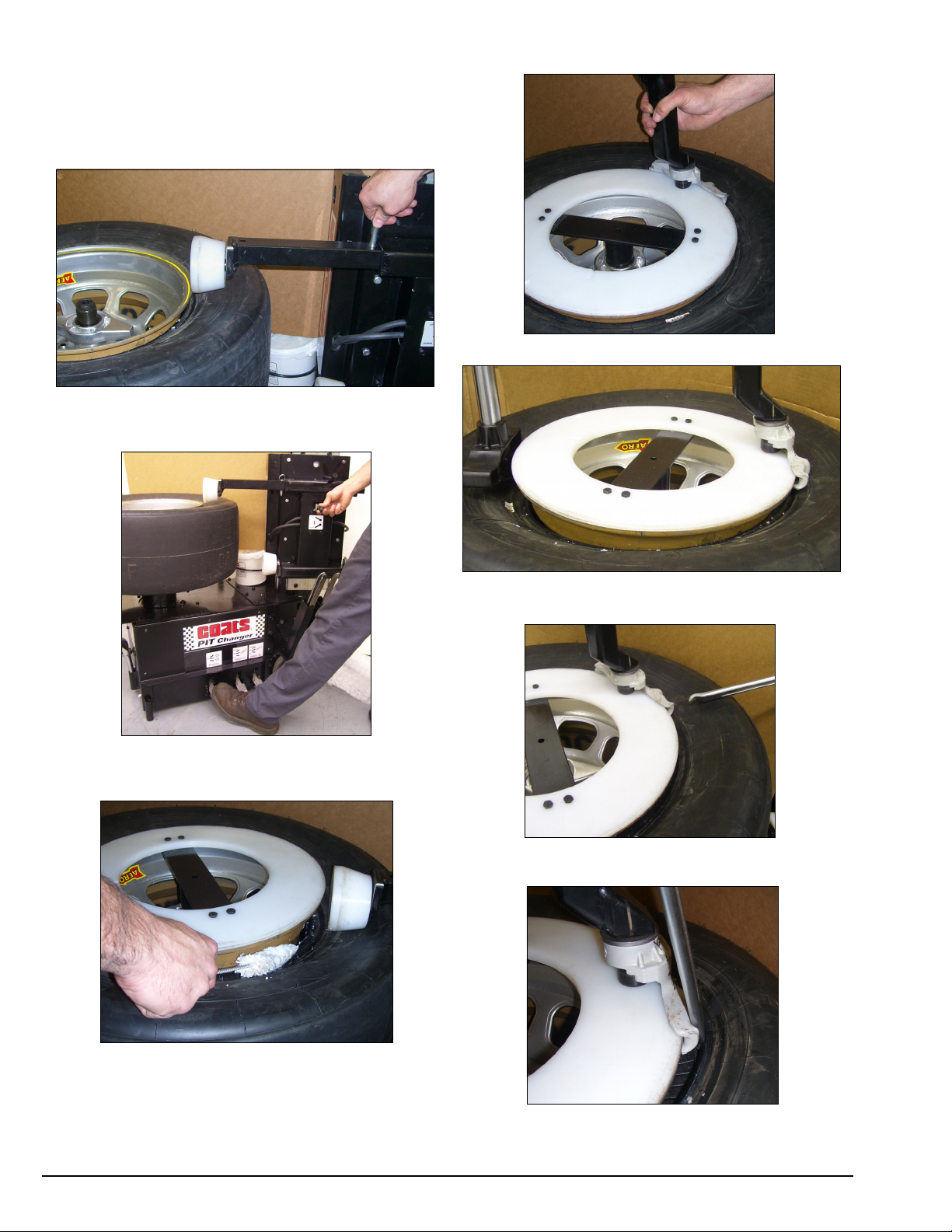
1. Begin the demounting process by placing the top
Power Roller at the edge of the rim and lock or pin the
movement.
2. Start by rotating the wheel using the foot pedal;
then use the hand valve lever and move the powered
roller downward to loosen the top tire bead.
3. Once the top bead has been pushed even with
the rim’s drop center, stop. Apply an ample amount of
lubricant to tire and liner beads. If the plastic protector
is to be used, place it on the rim.
4. Place duckhead on the rim’s top edge as shown.
5. Next, place the Robo Arm opposite duckhead and
press tire sidewall down even with rim’s drop center.
6. Retrieve lift tool and observe ends of lift tool. Use
end with small hook.
7. With the small hook end of the lift tool, position
the tool as shown. Be careful to only lift the tire bead;
do not lift the liner bead.
Page 7
Important: Always read and follow the operating instructions. • 3
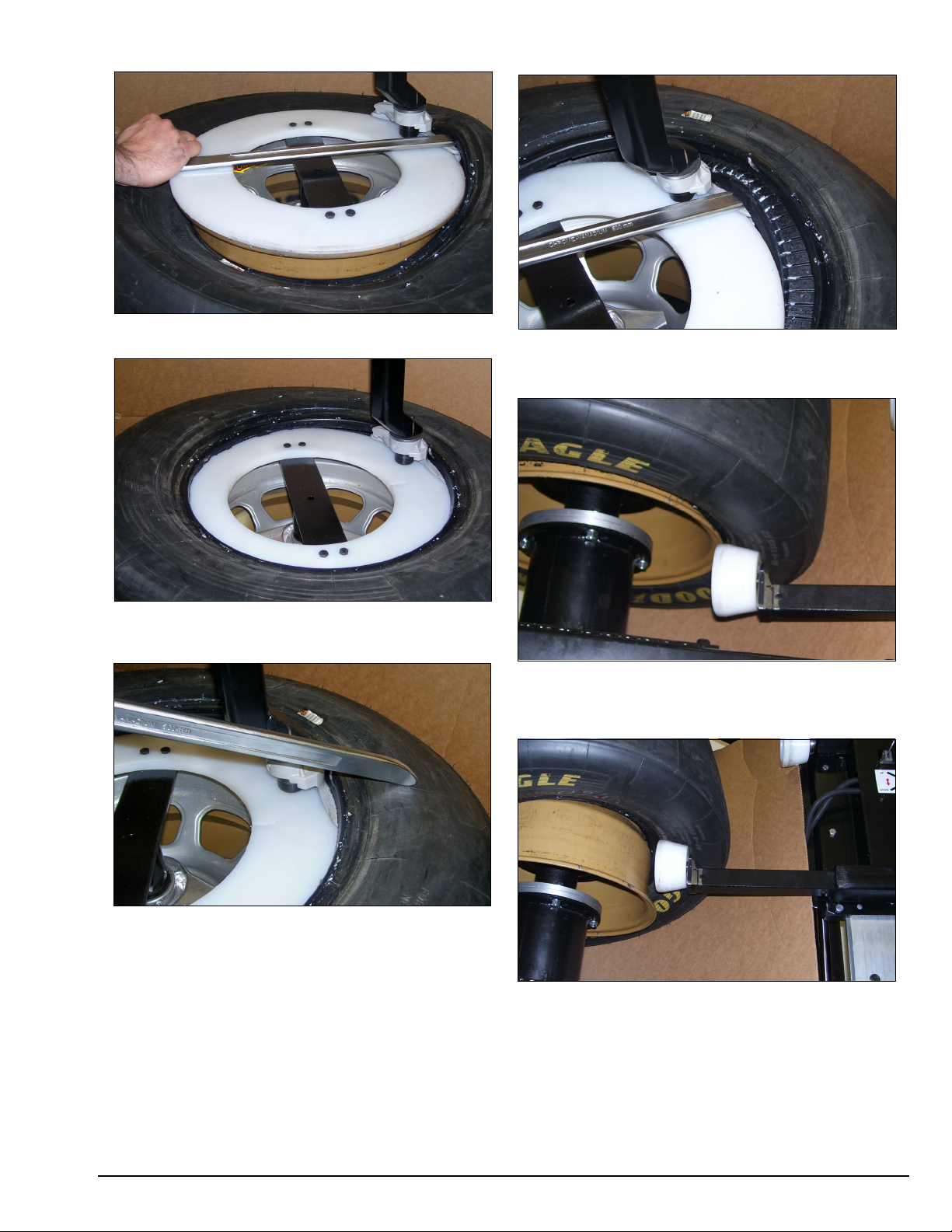
8. Rotate lift bar over slowly to position tire bead on
top of duckhead.
9. Move Robo Arm up and away from the tire and
rotate the wheel. Dismount top tire bead completely.
10. Use opposite end of lift tool to begin process of
removing the liner top bead. Use powered roller if necessary to press the tire sidewall down far enough to
grasp the liner’s top bead with the lift tool.
11. Rotate the lift bar over duckhead to lift the liner’s
top bead on to duckhead. Remove the liner’s top bead
completely.
12. Begin lower bead removal by positioning lower
powered roller near tire/rim intersection; place pin in
bar or lock to hold position.
13. Rotate tire and rim while moving bead loosener
roller slowly upward using hand valve. Continue bead
loosening until roller has pushed bead near the drop
center of wheel.
Page 8
4 • Important: Always read and follow the operating instructions.
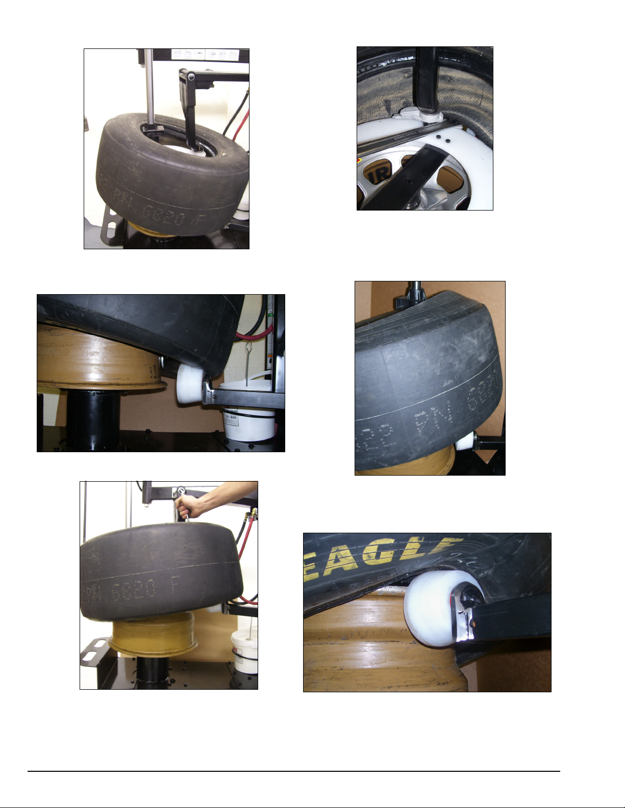
14. Position the robo arm opposite the duckhead, fix
the robo head under the tire and liner sidewalls and lift
up as shown.
15. Lubricate the tire and liner’s lower bead.
16. Insert the lift bar over the duckhead and under
the tire and liner’s lower bead.
17. Rotate the wheel and remove both tire and liner
lower beads.
Optional lower bead removal if plastic protector
has been removed.
18. After the lower beads have been loosened, posi-
tion the robo arm over the roller and pull UP on the tire
and liner.
19. Move the lower roller UP slowly to position
lower beads above the top flange of the rim. Next
rotate the rim and remove the tire and liner.
Page 9
Important: Always read and follow the operating instructions. • 5
Mounting a NASCAR Type Tire with a
Liner using the COATS PIT Tire Changer
Following are the steps:
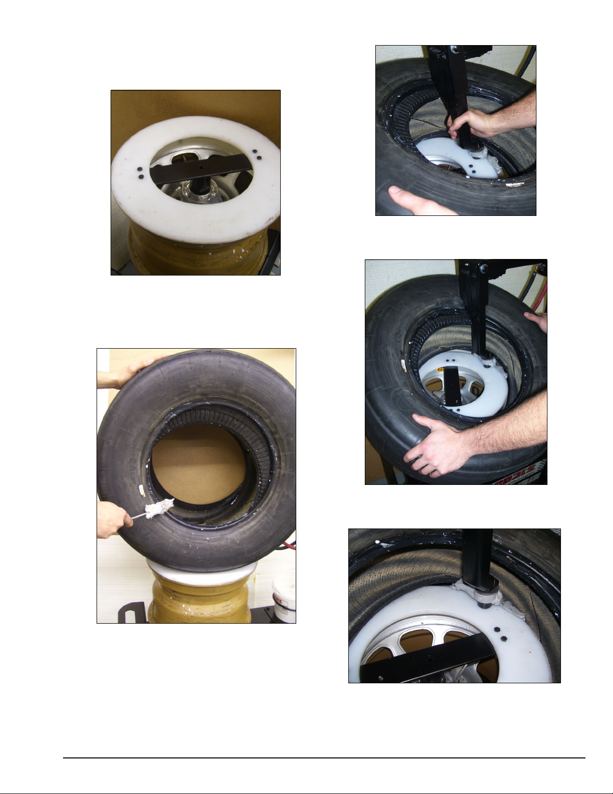
1. Mount inspected wheel on faceplate and engage
lug pins. Next thread centering nut on shaft. If the plastic protector is to be used, this would be the time to
install it with the small notch over the wheel’s inflation
valves.
2. Inspect tire and liner; next lubricate tire beads and
liner beads. Use ample amount of lubricant.
3. Position the tire/liner over rim and place duckhead
at the rim’s top edge; next position bottom bead of tire
onto duckhead; do not include lower liner bead.
4. Angle the tire as shown and press pedal to rotate
rim; first tire bead will mount onto rim; stop when
mounted.
5. Use rotation pedal (raise pedal upward) and
reverse rotation until the liner’s lower bead drops in a
mounting position on the duckhead. Next rotate wheel
in forward direction to mount lower bead of the liner.
Page 10

6 • Important: Always read and follow the operating instructions.
6. Next, maneuver the top sidewall of liner using the
bar as aid and press upper liner bead down over the
leading part of duckhead. Rotate wheel forward to
mount top liner bead.
7. Follow the bead lock around with bar until top liner
bead has been mounted.
8. Next, position top tire bead on duckhead as
shown, move upper powered roller on sidewall and
lower roller bottom edge until even with rim’s top drop
center. Next, position Robo arm as shown and press
sidewall down even with roller’s bottom edge.
9. Rotate rim and mount top bead, use care and
observe that the bead is flowing into the rim’s drop
center. Mount top bead complete and return the roller
to stowed position and return Robo to stowed position.
Page 11

Important: Always read and follow the operating instructions. • 7
Inflation
Tire inflation is performed in three steps: BEAD
SEAL, BEAD SEAT, and INFLATION. These steps are
explained in detail on page 14. Read the explanation of
each step and understand them thoroughly before proceeding.
Tire failure under pressure is hazardous.
This tire changer Will Not Restrain
Exploding Tires, rims or other related equipment. Inspect tire and wheel carefully for
match, wear, damage, or defects before
mounting. Always use approved tire bead
lubricant during mounting and inflation.
The clip-on chuck allows the operator to
keep hands and entire body back from
inflating tire. The chuck must be an
open/freeflow style with all parts in proper
working order.
Check for proper inflation gauge operation.
Accurate pressure readings are important to
safe tire inflation. Refer to the Operating
Maintenance section of this manual for
instructions.
The inflation pedals, located at the rear of the right
side of the machine, controls the flow of air through
the inflation hose, and has three positions.
Note:The clip-on chuck on the end of the hose should
always be an open/freeflow style with all parts in
proper working order.
Position 1 - Tire Pressure – With the inflation hose
attached to the tire valve and the pedal in this position,
the air gauge will register the air pressure in the tire.
Whenever your foot is removed from the pedal, it will
return to this position.
Position 2 - Tire Inflation – This is the DOWN activated position. With the inflation hose attached to the
tire valve and the pedal in this position, line pressure is
allowed to flow through the valve system and into the
tire for inflation. Correct tire pressure is not indicated
on the gauge in this position.
Position 3 - Pressure Bleed – This is the UP activated
position. With the inflation hose attached to the tire
valve and the pedal in this position, tire pressure can
be bleed from the tire.
Note the Inflation Pedal Positions (See Diagram)
Inflation Foot Pedals (two on right)
Note that this machine has two inflation circuits. One
for the tire and one for the liner.
Inflation Gauges
Note: Actual gauge face may vary depending on
model.
Note that there are two gauges. The front (left) gauge
is connected into the “A” inflation circuit. The rear
(right) gauge is connected to the “B” inflation circuit.
Twin Air Circuits
Clip-on air chucks attached to rim valves for tire and
liner inflation or bleed.
CAUTION
CAUTION
DANGER
Bleed
Pressure
From
Tire
POS 1 POS 2
POS 3
Page 12

8 • Important: Always read and follow the operating instructions.
Mismatched Tires and Wheels
Never attempt to mount and inflate mis-matched tires
and wheels.
Mismatched tire and wheel combinations can explode,
causing personal injury or death to operator and/or
bystanders.
DANGER
Half Size Tires
14.5, 15.5, 16.5, 17.5, etc.
Even Size Wheels
14.0, 15.0, 16.0, 17.0, etc.
15°
5°
Note the gap in sealing area
Bead may seal; but it
will not seat properly
Half Size Wheels
14.5, 15.5, 16.5, 17.5, etc.
Even Size Tires
14.0,15.0,16.0,17.0, etc.
Note 15° bead seat
Page 13

Important: Always read and follow the operating instructions. • 9
Stages of Inflation
Review these descriptions and diagrams carefully. Refer to them as
necessary during bead sealing, bead seating, and inflation to verify
that you are proceeding properly and safely.
Bead Sealing
Bead sealing is the process of capturing air pressure between the
tire and the rim. The tire will usually contain about 1/2 to 2 PSI at initial bead seal
Bead Seating
Bead seating usually occurs on the long tapered side of the wheel
first and the shorter side last. Bead seating will usually require at
least 7 PSI in the tire. 40 PSI is the maximum safe pressure at this
stage regardless of tire operating pressure.
Inflation
After the beads are seated, the tire is ready to be inflated. Do not
inflate the tire above the manufacturer’s recommended pressure as
stamped on the tire sidewall.
Air flow through valve requires about
140 PSI air pressure drop to ensure
sufficient flow on difficult tires.
Requires visual
conformation of
bead seat.
Stand clear of the tire during bead seat and inflation.
Stand clear of the tire during inflation.
Requires rubber lubricant on both upper
and lower beads.
Page 14

10 • Important: Always read and follow the operating instructions.
Bead Sealing
1. Position valve stem in front of operator and con-
nect the inflation hose with the clip-on chuck. Be sure
tire’s top bead does not cover the bottom of the valve
stem
2. Depress inflation pedal to position 2 and hold
about five seconds to begin air flow through tire valve.
3. Release the inflation pedal and allow it to return to
position 1. Verify that beads are completely sealed to
the wheel. Repeat these steps if beads have not
sealed. It may be necessary to wait a few seconds for
the air storage tank pressure to recover before
attempting again.
S. If tire and wheel are properly lubricated and
operator cannot achieve bead seal after three
or four attempts, the valve core may be
removed from the valve stem to allow more air
flow into the tire to assist with bead seal. After
bead seal is achieved, remove the clip-on
chuck and reinstall the valve core. Reattach the
clip-on chuck after core is installed.
Bead Seating
NEVER exceed 40 PSI to seat beads while
using this tire changer. If more than 40 PSI is
permitted by tire manufacturer, ALWAYS use
safety cage and clip-on chuck. NEVER
exceed recommended pressure after seating beads. ALWAYS keep hands and entire
body back from inflating tire.
An exploding tire, wheel, or bead sealing
equipment may propel upward and outward with sufficient force to cause serious
injury or death to operator or bystander.
Check tire pressure frequently. If operator is
unable to obtain Bead Seat, something is
wrong. Deflate tire completely, inspect tire
and wheel, correct any problems found,
relubricate both tire beads, and reattempt
Bead Seal and Seat procedures. Follow all
safety instructions in this manual and on
machine.
1. Once tire pressure is indicated on the air gauge
(inflation pedal in position 1; foot removed from pedal),
continue to inject air into the tire (inflation pedal position 2) in short intervals. Check the pressure frequently. Stand back during bead seat. Keep hands,
arms, and entire body away from tire during this procedure.
Inflation
NEVER exceed tire manufacturer's recommended air pressure. Tires can explode,
especially if inflated beyond these limits.
Use clip-on air chuck, keep hands, arms and
entire body back from inflating tire. Avoid
distraction during inflation. Check tire pressure frequently to avoid over inflation.
Excessive pressure can cause tires to
explode, causing serious injury or death to
operator or bystander.
1. Make sure both beads are seated. When both
beads are seated, the tire is ready for inflation.
2. Replace the valve core if it was removed.
3. Depress the inflation pedal to position 2 to inflate
the tire.
WARNING
WARNING
DANGER
Explosion Hazard
Never inflate tire
above
manufacturer's
recommended
pressure after bead
is seated.
DANGER
Explosion Hazard
Never exceed 40
PSI while seating
beads.
Remember R.I.M.
(see page iv and back cover)
DANGER
Remember R.I.M.
(Read, Inspect, Mount)
for every tire.
Page 15

Important: Always read and follow the operating instructions. • 11
4. Release air pressure from tire by raising up on the
inflation pedal (inflation hose must be attached to the
valve stem. Never add or adjust tire pressure using an
air hose without a clip-on air chuck and in-line valve. Do
not use a hand-held style chuck (figure 1).
5. Important: When inflating tires that require more
than 60 PSI, always use a safety cage and air hose with
a clip-on air chuck and in-line valve. The air hose must
have enough length between the chuck and the operation/in-line valve to allow the operator to stand outside
the trajectory.
Note: If you change tires defined as truck tires, they
must be inflated per OSHA instructions.
Figure 1 - Do Not Use a Hand-held Style Air Chuck
Maintenance
Instructions
Read and follow all the maintenance instructions provided in this manual to keep the machine in good operating condition. Refer to the other materials received
with the unit and to the service bulletins from the manufacturer for additional instructions on proper maintenance and service. Regular inspections and proper
maintenance are essential to preventing accidents and
injuries.
Before making any inspection, adjustment,
or repair, disconnect all power sources and
block out all moving parts to prevent injury.
Keep the machine and the immediate work
area clean. Do not use compressed air to
remove dirt and debris from the machine.
Foreign material may be propelled into the
air and into operator or bystander causing
personal injury.
Wear protective clothing, equipment and
eye protection when making any adjustments or repairs to the machine.
A. Check the adjustment of the Duckhead once a
month.
B. The transmission in this machine is a sealed unit
packed with grease and should need no normal maintenance.
C. Check the tire pressure gauge function daily, and
check the accuracy monthly. Use a pressurized tire and
a high quality stick-type pressure gauge. If necessary,
adjust the dial of the machine gauge. If the gauge is
defective, replace it immediately. Contact COATS at
(615) 641-7533.
D. Make sure all fasteners are securely tightened.
E. Make certain that all guards and covers are in
place.
F. Check for worn, damaged or missing parts including grips and protective covers. Replace them before
allowing the unit to be used.
WARNING
WARNING
WARNING
Page 16

G. On a daily basis, inspect the unit and check to be
certain that all systems are operating normally.
Detailed inspection and testing procedures are specified for various components at regular intervals. Set up
a chart and assign responsibility for these items.
Replace any damaged or missing safety
decals. They are available from COATS, (800)
688-6359.
Important: These instructions will help you service
the unit. Instructions are for a person with some
mechanical ability and training. No attempt has been
made to describe all basic steps. For example, how to
loosen or tighten fasteners. Also basic procedures
such as cycling systems and checking operation of the
equipment are not fully described since they are
known to anyone who does mechanical and service
work. Do not attempt to perform work beyond your
ability or at which you have no experience. If you need
assistance, call an authorized service center or contact
COATS directly, (800) 688-6359.
Separator/Lubricator Maintenance
Check oil and water levels regularly, and perform
these maintenance items weekly:
A. Disconnect air supply to machine.
B. The Separator (Filter) unit is equipped with an auto-
matic drain and should not normally need draining.
C. If the fluid level is greater than 1/4" from the top of
the gauge, add oil. Remove the filler plug on top of the
lubricator and add SAE 10W non-detergent oil or an air
tool oil to bring the level up to 1/4" from the top of the
gauge. Replace filler plug and clean up any spilled oil.
D. Adjust the oil flow by turning the black flow adjust-
ment knob and turning it to increase or decrease the
flow. Watch the formation of oil drops in the seethrough oil chamber. Reconnect the air supply and continually cycle the bead loosener through full strokes
and count the drips during the cycles. The delivery of
oil to the airline should be about 1 drop per 10 cylinder
cycles. Adjust flow as required.
Never inflate tire above manufacturer’s recommended pressure after bead is seated.
Any required inflation above 60 PSI should
be performed in an inflation chamber/safety
cage or securely mounted on the vehicle if
an inflation chamber is not available. A tire
explosion may cause personal injury or
death to operator or bystanders.
Air Source
This model requires a a 5 CFM air source at 150 PSI.
The operating pressure range for all models is between
125 PSI and 175 PSI at the machine.
Electrical Source
Electric models require power from a 30 amp, 120
volt electrical circuit. Have a licensed electrical technician perform any necessary changes to the power
source before plugging in the unit. The electrical source
must have a solid connection (less than 1 ohm)
between ground and building ground.
DANGER
CAUTION
12 • Important: Always read and follow the operating instructions.
Oil Flow
Adjuster
Knob
Air Out
Reg
G
Auto Drain
Outlet
Separator
Lubricator
Oil Fill
(Behind Oil
Flow Adjuster)
Oil Level
Check
A
Regu
Adjus
Kn
Air Out
Page 17

Important: Always read and follow the operating instructions. • 13
Parts Identification
Chassis Assembly
1 1
2 2
3 3
4 4
5 5
6 6
7 7
11 11
8 8
9
10
10
CHASSIS ASSEMBLY
Ref Part No. Description
1 8106301 1/4-20 x 3/4" Hex Washer Screw
2 8185649 Front Cover
3 8185473 Chassis w/c NASCAR
4 8140567 1/2-13 UNC Nut
5 85000638 Pilot Shaft
6 85000637 Spacer Block
7 85000636 3 x 1-1/4" Swivel Caster Wheel
8 905659 1/2-13 UNC - 2 x 1-1/2 Hex Hd Cap
Screw
9 8185628 Motor Side Cover
11 85000493 Shaft Housing, w/c
12 8106302 3/8-16 x 7/8 Hex Washer Screw
Page 18

Foot Pedal Assembly
14 • Important: Always read and follow the operating instructions.
1 1
2 2
3 3
4 4
5 5
6 6
7 7
8 8
9 9
11 11
12 12
13 13
17 17
18 18
19 19
20 20
21 21
23 23
24 24
27 27
15 15
33 33
31 31
35 35
36 36
32 32
25 25
10 10
34 34
14 14
29 29
16 16
30 30
TORQUE TO 4 - 8 ft./lb.TORQUE TO 4 - 8 ft./lb.
Ref Part No. Description
1 8106301 1/4-20 x 3/4" Hex Washer Screw
2 8183398 Pedal Shaft
3 8111609 Hairpin Cotter
4 8181948 Nylinder Bearing
5 8181911 Pedal Spacer
6 8181675 Standard Pedal
7 85000580 Pedal Spacer
8 8182670 Guide Bracket
9 8181918 Bar Spacer
10 8181707 Torsion Spring
11 8181977 Pin Clevis
12 8120469 Hair Pin Clip
13 8301121 0.562 ID Plain Washer
14 8181983 10-24 x 0.75, BHSCS Screw
15 8181699 Lever Cam Follower
16 8182363 Electric Bracket, Switch Ext.
17 8181982 3 x .5 x 12 mm Lg HHCS Screw
18 8301072 #6 Internal Washer
19 8182682 10/24 UNC Nylock Hex Nut
20 8107635 5/16 Std Flat
Ref Part No. Description
21 8181728 Switch Actuator Lever
23 8184389 Reversing Switch, Switch Only
(Note: Cord/Plug & Motor Wiring
Part of 81827336 Switch Assembly
Complete, Not Shown.)
81827336 Switch/Cord Wiring Assy Complete
24 8181959 Rubber Boot Cover
25 *** 4/way Valve Assembly
27 85000491 Switch/Valve Bracket
29 8184376 25 AMP Circuit Breaker
30 8181989 10-24 x 3/8, Gr 8 SHCS Screw
31 8182743 10-24 x 1/2, Gr 8 SHCSS Screw
32 8181984 1/4-20 x 1" HHC Screw
33 8182682 #10-24 Rvrsble Lk Hex Nut
34 8181369 1/4-20 Nylock Hex Nut
35 8181923 STOP WASHER (K)
36 8104945 SCREW-HWHSTC, 1/4x1, GR.5
*** See Valve Assemblies page 23.
Page 19

Important: Always read and follow the operating instructions. • 15
Table Top Assembly
1
6
8
9
10
11
12
2
7
3
4
5
Ref Part No. Description
1 85000489 Table Top Hub
2 85000490 1/2-13 x 3/4" Stud
3 8182979 Special Shaft Washer
4 85000664 40mm Stub Shaft
5 85000665 5/8-11 x 6" SHCS
6 85000662 Small Pressure Drum
7 8110514 Retainer Spring
8 85000661 Hub Nut Handle
9 8143169 1/4-20 Whz Lk Hex Nut
10 85000692 Tube & Bar/Handle w/c
11 85000645 NASCAR Locator Ring
12 8120321 1/4-20 NC x 1-1/4 HHCS
12
11
10
9
8
7
6
5
4
3
2
1
Page 20

Shaft Housing Assembly
16 • Important: Always read and follow the operating instructions.
Ref Part No. Description
1 904425 Hex Cap Screw
2 8106303 3/8-16 UNC Nut
3 8110653 3/8-16 x 6" Screw
4 8185546 Transmission Assembly
5 85000287 2 HP Motor
6 8301032 3/8" Flat Washer
7 8106303 3/8-16 UNC Nut
8 85000762 4L3100 V Belt
9 8120325 5/16 x 1.00 Serrated
10 8184674 Motor Pulley
11 8185485 Motor Bracket
12 8182178 Whiz Lock Nut
13 85000486 Housing Support Assembly
13
1
2
3
TORQUE TO
20-25 ft. / lb.
4
5
6
7
12
11
10
9
8
Page 21

Important: Always read and follow the operating instructions. • 17
Horizontal Slide Assembly
2
4
3
9
11
10
12
13
15
16
17
19
6
5
1
14
8
18
22
23
24
26
25
Ref Part No. Description
1 ** Cylinder Assembly
2 8185555 Flange Bushing
3 8185558 1/2" Shoulder Screw
4 8185575 Shaft Assembly
5 920861 20 x 47 x 14 Bearing
6 8185544 4" Nylon Roller
8 8185550 0.5100-78 Retaining Ext. Ring
9 8120424 3/8-16 UNC Washer
10 85000408 Gib Backup Bar
11 8184837 Long Guide Gib
12 8301122 1/2-13 Hex Nylock Nut
13 8185614 Horizontal Slide Assy.
14 8185562 Cam-lock Assmy w/handle
15 906101 3/8-16 x 2.00 HHCS
Ref Part No. Description
16 *** Vert. Slide Valve Assmy
17 8185615 Valve/Lube Brkt Mount Bracket
18 8143844 1/4-20 x 1/2" Hex Washer Hd Scrw
19 8106301 Hex Washer Head Screw
22 8185553 Wave Spring Washer
23 8000516 Nut, Hex, Lock, 3/8-16
24 8102278 1/8 x 1" Cotter Pin
25 8107238 7/16 x 2-1/8" Clevis Pin
26 8120088 7/16 x 1-3/4" Detent Pin
** See Cylinder Assembly page 22.
*** See Valve Assemblies page 23.
24
26
9
10
11
12
13
22
14
15
23
16
17
18
19
2
3
4
5
6
8
25
1
APPLY GREASE TO THESE LOCATIONS
Page 22

18 • Important: Always read and follow the operating instructions.
Pressure & Inflation Bracket System
1
2
3
4
5
7
10
13
14
17
18
15
25
28
29
31
32
35
36
37
27
26
16
34
11
44
8
45
46
39
38
42
41
40
48
49
12
43
24
47
6
9
19
30
21
22
23
TORQUE TO 240 ft./lb.
33
TORQUE TO 240 ft./lb.
11
10
9
8
44
12
13
47
14
37
36
35
15
16
17
18
19
45
39
25
21
26
38
22
27
23
24
46
28
29
30
31
34
41
32
33
42
43
1
48
49
40
Page 23

Important: Always read and follow the operating instructions. • 19
Ref Part No. Description
1 8108852 3/8 Whiz Lock Screw
2 85000499 Rear Leg
3 8185475 Welded Tower Assembly
4 8106303 3/8-16 UNC Nut
5 85000609 Lube Bracket
6 8143844 1/4-20 x 1/2 Hex Washer Hd
7 8183710 Mounting Cream
8 8185636 Channel
9 8182221 Clamp
10 85000658 Plate/Shaft Assembly
11 8140825 1/2-13 x 1-1/4" HHCS
12 8101253 7/8 x 1-1/2"
13 8120099 BL Cylinder Wheel
14 8102278 1/8 x 1 Cotter Pin
15 8182458 Tower/Reservoir Cap
16 8182599 1/4 NPT Relief Valve
17 8108968 1/8" NPT Air Gauge, 0-300
18 8183434 Manifold
19 8101898 3/8 x 1/4 NPT Fitting Hose
21 8100979 Handle Grip
22 8106302 3/8-16 x 7/8 Hex Washer Screw
23 85000605 Handle Assembly
24 8106301 Hex Washer Head Screw
25 8183770 Filter/Lubricator Bracket
26 8184868 Vertical Slide Plate
27 8182827 Filter/Lubricator w/Auto Drain
28 8185533 Gauge Mount Bracket
29 8108852 3/8 Whiz Lock Screw
30 85008946 Air Gauge, 100 PSI
31 8301063 #6-32 x 1/2" Screw
32 8120325 5/16 x 1.00 Serrated
33 8185651 Tool Holder Assembly
34 8181354 Lift Tool
35 8182016 3/4-10/E23 Nylock Hex Nut
36 8182457 3/4 SAE Flat Washer
37 8181172 3/4-10 x 7-1/2, Gr5 HHCS Screw
38 8301066 #6-32 Kep Nut
39 8120424 3/8-16 Hex Washer Hd.
40 8112842 950 Racer Wheel
41 8185623 NASCAR Wheel Shaft
42 8103006 5/32 x 1-1/4 Cotter Pin
43 8100994 3/4 x 2" Flat Washer
44 8000491 Lube Applicator
45 8106278 Tee Male Branch
46 8184467 1/4 NPT x 3/8 x 3/8 Tee Fitting
47 8181369 1/4-20 Nylock Hex Nut
48 8120491 3/4 x 3/8 NPT Reducer Fitting
49 85000083 90° ELL 3/8 NPT x 3/8 Hose Fitting
Page 24

20 • Important: Always read and follow the operating instructions.
Robo Arm Assembly
17
18
19
20
21
11
12
14
15
16
1
2
3
4
5
6
7
8
9
10
13
Ref Part No. Description
1 8183703 Hex Head Cap Screw
2 8100994 Flat Washer
3 8183641 Foot
4 905563 Roll Pin
5 8 301017 Steel Ball
6 8183637 Retaining Ring
7 7000230 Handle Grip
8 8181983 10-24 x 0.75 BHSCS Screw
9 *** Helper Arm Valve Assembly
10 8183644 Special Cylinder
11 8181997 90° ELL Fitting
12 8181996 Straight Male Fitting
13 8182016 3/4-10 UNC Lock Nut
14 8100994 Flat Washer
15 85000640 Arm Front Weldment
Ref Part No. Description
16 8183649 Socket Hd. Set Screw
17 8184226 1/4-28 Grease Fitting
18 8181038 Pivot Pin
19 8184904 Rear Arm Weldment
20 8182044 Neoprene Cushion Clamp
21 8106301 Hex Washer Head Screw
*** See Valve Assemblies, page 23.
10
11
12
13
14
9
15
8
7
6
16
5
4
3
17
18
19
20
21
TORQUE TO 240 ft. / lb.
APPLY GREASE TO THESE LOCATIONS
Page 25

Important: Always read and follow the operating instructions. • 21
Auxiliary Arm Assembly
1
2
3
4
5
11
13
14
15
6
7
8
9
10
18
19
12
16
17
Ref Part No. Description
1 8113583 3/8-16 x 1-3/4 Flat Hd Soc Cap Scr
2 85000644 Duckhead Spacer
3 8184426 Mount/Demount Head
4 8183033 Washer/Spacer
5 85000513 Mount/Demount Arm
6 8102278 Cotter Pin
7 85000542 Spring Plunger Assembly
8 8143168 Whiz Lock Screw
9 8104149 Valve Spring
10 8104154 5/8 x 4-1/2" Clevis Pin
Ref Part No. Description
11 8184226 1/4-28 Grease Fitting
12 8101039 1/2-13 Hex Center Lock Nut
13 309008 Stop Mounting
14 8106301 Hex Washer Head Screw
15 85000660 Plate/Shaft Assem w/c
16 8181038 Pivot Pin
17 8185639 Duckhead Arm Assembly
18 85000538 Bearing Bushing
19 8107662 1/2-13 x 5" Screw
10
12
11
13
14
16
17
15
18
19
1
Page 26

22 • Important: Always read and follow the operating instructions.
Cylinder Assembly
1
2
3
4
5
6
7
8
9
10
11
12
13
14
Ref Part No. Description
1 8184892 Aux Cylinder Shaft
2 85008900 Tie Bolt Clamping
3 8183772 1/16 x 1/2 x 5/8 O-ring
4 85000332 90° Elbow Fitting
5 8110497 90° Elbow Fitting
6 8181620 Cylinder Bottom Casting Cap
7 8181631 O-ring Seal
8 8183786 Cylinder Rod Seal
9 8181632 Nyliner Sleeve Bearing
10 8184525 Piston/Washer Assembly
11 8182719 Hex Lock Nut
12 85008899 Cylinder Sleeve
13 8181622 Cylinder Bottom Casting Cap
14 8181183 5/16-18 Nylon Insert
15 85008898 Cylinder Assembly
1
2
3
4
5
6
7
8
9
10
11
12
13
14
*HOR. SLIDE CYLINDER ASSY.
Page 27

Important: Always read and follow the operating instructions. • 23
Valve Assemblies
2 2
1 1
3 3
3 3
2 2
1 1
4 4
5 5
1 1
2 2
3 3
4 4
5 5
HOR. SLIDE ASSEMBLY VALVEHOR. SLIDE ASSEMBLY VALVE
ROBO ARM ASSEMBLY VALVE ROBO ARM ASSEMBLY VALVE
PEDAL ASSEMBLY VALVE (ELEC.)PEDAL ASSEMBLY VALVE (ELEC.)
*
Ref Part No. Description
1 906960 1/4 NPT Bronze Muffler
2 8185621 3-Position Valve
3 8000378 Straight Fitting
Ref Part No. Description
1 8181997 Fitting
2 8109481 1/4-1/8 NPT Reducer Fitting
3 8185585 3-Position Valve
4 8105615 1/4 NPT Muffler
5 8000378 Straight Fitting
Ref Part No. Description
1 8184256 90° ELL Fitting
2 906960 1/4 NPT Bronze Muffler
3 8184369 Pedal Operated Valve
4 8120344 1/4 NPT Pipe Plug
5 8107234 1/4-3/8 Brass Tee Fitting
* 85008891 Four Way Valve Assembly
Page 28

85000681 00 10/07 © Copyright 2007 Hennessy Industries and COATS All Rights Reserved Printed in USA
Wiring Diagram
 Loading...