

Page 1
Wheel Lift
Kit 85608609
For use with COATS Models 50xx, 60xx, 70xx
This is a supplement to your operating manual and covers the setup and use of the COATS® Wheel Lift. If you
do not have your original operating manual, please call COATS at 1-800-688-6359 to request an additional copy.
User Instructions
with Parts Identifi cation
READ these instructions before placing unit in
service. KEEP these and other materials delivered
with the unit in a binder near the machine for ease
of reference by supervisors and operators.
1601 J. P. Hennessy Drive, LaVergne, TN USA 37086-3565 615/641-7533 800/688/6359 www.ammcoats.com Manual Part No.: 85608611 02
HENNESSY INDUSTRIES INC. Manufacturer of AMMCO
®
, COATS® and BADA® Automotive Service Equipment and Tools. Revision: 01/14
Page 2
Wheel Lift Setup
CAUTION
Always DISCONNECT THE ELECTRICAL
POWER before servicing equipment. This
prevents electrical shock or accidental
movement of the systems operated by the
electrical power.
CAUTION
Always DISCONNECT AIR SUPPLY before
servicing equipment. This prevents accidental movement of systems operated by compressed air which may result in personal
injury. BLEED THE AIR SYSTEM by actuating
all the valves.
CAUTION
STAY CLEAR OF MOVING PARTS when
reconnecting the unit of the air supply. The
position of control valves may have changed
during the servicing of the machine.
50xx, 60xx, 70xx Series Instructions
Before beginning this modification or attempting
any maintenance, remove the electrical power and air
source from the machine; also, bleed off any stored
compressed air by exhausting through the air blast foot
valve.
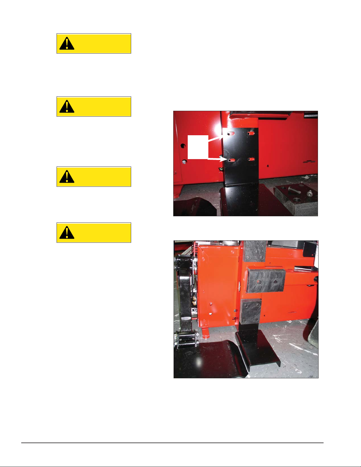
1. Remove the lower bead loosener pad; reserving
the bolts.
2. Next, align slots in the anit-tip bracket with the
holes in the chassis were the lower bead loosener pad
was attached.
Align to
Left End
of Slots
CAUTION
Do not operate machine without the anti-tip
bracket installed. It is required for maximum
machine stability, when wheel lift is operated under load that would shift the center
of gravity.
3. Now reassemble the lower bead loosener pad over
the anti-tip bracket, as shown.
2 • COATS
Page 3
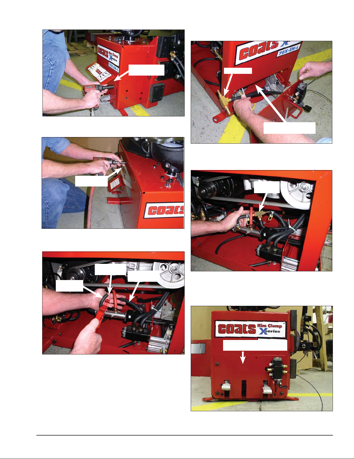
4. Remove pedal bracket guard and reserve the bolts.
7. Find the tee fitting, on the new pedal bracket
assembly, and route it through the front opening to the
inside of the chassis.
Remove Pedal
Bracket Guard
5. Remove the machine’s side panel using a speed
handle or drill and 3/8-inch socket.
Remove Side
Panel
Tee Fitting
Route Hose with Tee
Fitting Inside Chassis
8. Install the tee fitting, from the new pedal bracket
assembly, into the just cut 3/8-inch hose and secure
using hose clamps.
Install Tee
Fitting
6. Locate and cut in half the 3/8-inch hose that con-
nects the oil injector to the first pedal valve.
Cut 3/8-inch
Hose
Hose From
Oil Injector
Hose To First
Pedal Valve
9. Use three of the four reserved bolts to fasten the
new pedal bracket assembly to the front of the machine
chassis. Note the pedal valve’s position makes it so the
fourth both cannot be fastened.
Fasten Pedal Bracket
Assembly To Chassis Front
COATS • 3
Page 4

10. Remove two bolts from transmission (see step
8). Reserve bolts for later use.
11. Place lift mounting bracket on chassis and align
on the holes. Now install the lift mounting bracket to
the chassis using the two reserved bolts from step 10.
Important: Torque bolts at 30 foot pounds.
14. Assemble the lift pad to the lift assembly using
the supplied shoulder bolt. Be sure to grease the shoulder bolt and tighten it securely.
Install Lift Mounting
Bracket
12. Install the wheel lift assembly to the lift mount-
ing bracket using three thread cutting screws.
13. Route the two 1/8-inch tubes, from the lift pedal
valve, behind the lift bracket and connect the tubes to
the lift cylinder.
Fasten Wheel Lif t
Assembly
Fasten Lift Pad
Using Should Bolt
15. Reconnect air supply and machine test checking
for air leaks.
Important: Upon initial air supply connection, it is
normal if the Tire Lift jumps 2 or 3 inches the first time
it lifts, so be careful and expect that to happen.
16. Attach the new pedal bracket cover using sup-
plied thread cutting screws.
Fasten New
Pedal Guard
Apply Pedal And
Clamp Decals
Connect Cylinder
Tub es
17. Apply new pedal and clamp instruction decals.
18. Reassemble side panel.
4 • COATS
Page 5

Wheel Lift Operating Instructions
CAUTION
Do not operate machine without the antitip bracket installed. It is required for maximum machine stability, when wheel lift is
operated under load that would shift the
center of gravity.
1. Position table top as shown with open portion of
the table top facing the wheel lift.
3. Roll tire off wheel lift platform and onto the back
of the clamp that is located at the back of the machine
closest to wheel lift.
2. With wheel assembly on wheel lift. Keep wheel
vertical and push foot pedal down to raise wheel up.
4. With the tire resting on the back of the clamp,
lower it so that the rim fits in the clamps.
5. Push foot pedal up to lower wheel lift before performing tire change.
COATS • 5
Page 6

Parts Identifi cation
Note: Fittings have a sealant coating as
purchased. If absent, be sure to apply teon
tape or thread sealant at installation.
6
5
4
3
2
5
16
15
17
3
1
14
8
32
29
30
33
31
34
33
32
37
7
13
12
21
20
20
19
22
9
10
23
11
27
25
24
Lift Pedal
Valve
25
26
26
28
16
18
11
6 • COATS
Page 7

ITEM PART NO. DESCRIPTION
1 85608597 Lift Cover
2 8106301 1/4” Hex Hd Self Tap Screw, Gr.5
3 85606919 Ext. Retaining Ring
4 85606917 Flat Washer
5 8181996 Male Straight Fitting
6 85608531 Lift Cylinder Assembly
7 8102459 3/8” Self Tap Screw Gr.5
8 85608587 Chassis Mount Bracket
9 85608588 Lift Mount Assembly
10 8106303 3/8” Whiz Lock Nut, Gr.5
11 8120055 Clamp Carrier Nut
12 85608592 Lift Upper Arm
13 85608595 Lift Lower Arm
14 85608591 Lift Pivot Bracket
15 8106302 3/8” Whiz Lock Screw, Gr.5
16 85608606 SHSS Screw
17 85608602 Lift Pivot Cylinder Rod
18 85608598 Lift Pad
19 8105822 9/16 I.D. Hose Clamp
20 85607855 1/4 NPT Muffler, Small
21 8000376 ELL 90º 1/4 Hose Fitting
22 8181983 0.375-16 Hex Whizlock Nut
23 85608603 Valve Pedal
24 8182682 10-24 Nylon Insert Lock Nut Gr.5
25 8109481 1/4 NPT x 1/8 NPT RDCR Fitting
26 8181997 90º Elbow 1/8 NPT x 1/8” Fitting
27 85608534 Lift Valve
28 85608571 Bracket Assembly
29 902189 1/4-20 x.504 HHCS
30 85606362 13mm Spring Hose Clamp
31 8000378 1/4” Brass St. Fitting
32 85606363 16mm Spring Hose Clamp
33 8101898 St. 1/4” NPT 3/8” Hose Fitting
34 8000643 1/4” NPT Tee
**35 8099050 1/4” Hose
**36 8099075 1/8” Tube
37 85609355 Anti-tip Bracket
**Not Shown
COATS • 7
Page 8

85608611 02 01/14 © Copyright 2013 Hennessy Industries and COATS All Rights Reserved
 Loading...