

Page 1
Locking Swing Arm
Kit 85607983
For use with COATS 50/70X and Tire Changers
This is a supplement to your operating manual and covers the installation of a COATS® Locking Swing Arm. If you
do not have your original operating manual, please call COATS at 1-800-688-6359 to request an additional copy.
User Instructions
with Parts Identifi cation
READ these instructions before placing unit in
service. KEEP these and other materials delivered
with the unit in a binder near the machine for ease
of reference by supervisors and operators.
1601 J. P. Hennessy Drive, LaVergne, TN USA 37086-3565 615/641-7533 800/688/6359 www.ammcoats.com Manual Part No.: 85607955 00
HENNESSY INDUSTRIES INC. Manufacturer of AMMCO
®
, COATS® and BADA® Automotive Service Equipment and Tools. Revision: 05/12
Page 2
Locking Swing Arm
Installation
CAUTION
Always DISCONNECT THE ELECTRICAL
POWER before servicing equipment. This
prevents electrical shock or accidental
movement of the systems operated by the
electrical power.
CAUTION
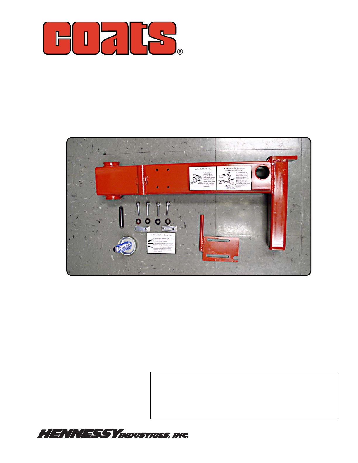
Parts Identification
Swing Arm Locking Mechanism
(Leverless Unit)
2
1
6
5
4
3
Always DISCONNECT AIR SUPPLY before
servicing equipment. This prevents accidental movement of systems operated by compressed air which may result in personal
injury. BLEED THE AIR SYSTEM by actuating
all the valves.
Apply Grease To These Locations
Item Part No. Description
1 85607820 Adjusting Lock Knob
2 85000317 5/16-18 x 1-1/2 HSWHCS Screw,
Zinc
3 8107635 5/16-inch Plain Washer
4 85607814 Swing Arm Lock Plate
5 83030571 Lock Block
6 7000230 1/2 x 3 Handle Grip
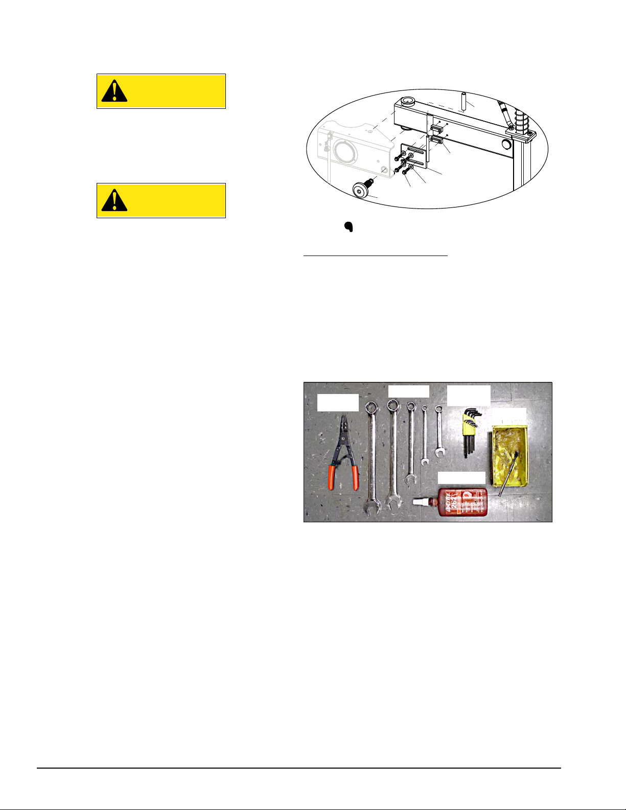
Tools Required:
Snap Ring
Pliers
Wrenches
Allen
Wrenches
Grease
Threadlock
Grease
Threadlock
Snap Ring Pliers
Allen Wrenches
Wrenches, 1-1/8", 1-1/16", 3/4", 5/8", 1/2"
2 • Important: Always read and follow the operating instructions.
Page 3

Instructions
1. Before beginning any work, clear the area and
position the machine for easy access. Disconnect
the electrical power and air supply from the machine;
empty all residual air.
2. Disconnect the leverless bead lifter coil air hose
from fitting installed on top of the swing arm bracket
(figure 1).
Disconnect Coil
Air Hose
Figure 1 - Disconnect Coil Air Hose From Fitting
3. Next, remove the vertical slide with leverless
assembly from the swing arm (figure 2). First, lock
vertical slide in the fully up position. Using an allen
wrench, remove bolt and knob at top of vertical slide;
then remove vertical slide spring. Now unlock the vertical slide and lower it out of the swing arm shaft.
5. Use wrenches to loosen swing arm bolt and nut.
While supporting the swing arm, remove and reserve
the bolt, nut, and pivot pin, then remove old swing arm
from tower (figure 3).
Figure 3 - Remove Old Swing Arm From Tower
Note: This would be a good opportunity to grease
parts.
6. Next, install the new swing arm using the reserved
bolt, nut and pivot pin. Assemble with the bolt pushed
up from bottom and torque to 240 ft. lbs.
7. Use reserved snap ring (figure 4) and reinstall the
lock handle/lift cam onto the new swing arm.
Remove Screw,
Knob & Spring
Unlock Vertical
Slide
Lower Assembly
& Remove
Figure 2 - Remove Vertical Slide With Leverless Assembly
4. Remove the vertical lock plate assembly and snap
ring holding the lock handle/lift cam. Reserve parts for
later use.
Snap Ring
Figure 4 - Reinstall Snap Ring To Lock Handle/Lift Cam
8. Reassemble the vertical slide with leverless
assembly to the new swing arm. Verify the lock handle
is working correctly.
9. Reattach the reserved vertical lock plate assembly
to the new swing arm Refer to owners manual for
adjustment procedure.
10. Reinstall vertical slide spring. Apply threadlock
to the reserved bolt, then reassemble knob and bolt.
11. Reconnect the leverless bead lifter coil air hose
to the fitting installed on top of the swing arm bracket.
Important: Always read and follow the operating instructions. • 3
Page 4

11. Remove existing adjusting knob and replace
with supplied adjusting lock knob (figure 7).
12. Now install handle grip onto swing arm lock
plate. Grease both sides of the lock plate grooves.
(figure 5)
Grease Lock
Plate Grooves
Install Handle
Grip
14. Mount the swing arm lock plate assembly to the
swing arm. Tighten in a criss-cross pattern. Verify swing
arm lock engages adjuster knob correctly. Final tighten
bolts and verify that the lock moves freely. (figure 7)
Adjusting
Lock Knob
Verify Lock
Engages Properly
Figure 7 - Verify Swing Arm Lock Function
Figure 5 - Prepare Swing Arm Lock Plate
13. Position lock blocks in plate grooves; then add
the four washers and bolts (figure 6). Apply threadlock
to bolts before tightening bolts.
Figure 6 - Assemble Swing Arm Lock Plate Hardware
Remember: Generously lubricate all friction points for
improved function.
15. Apply instruction decal below table top on top of
chassis (figure 8).
Figure 8 - Instruction Decal Placed On Chassis
16. Perform machine functional test.
85607955 00 05/12 © Copyright 2012 Hennessy Industries and COATS All Rights Reserved
 Loading...