

Page 1
Extended Mobility (EMT)
RunFlat Tires
Training Manual
Bead Loosening, Demounting, Sensor Installation,
Mounting, and Inflation Procedures
prepared and presented by
FOR DISTRIBUTION
HENNESSY Part No.: 183708B
Name: Date:
Instructor: Location:
Page 2

Page 3

Table of Contents
i
EMT Training Objectives……………………………………………………………ii
Course Timetable…………………………………………………………………iii
Overview……………………………………………………………………Section A
Safety………………………………………………………………………Section B
Tools & Equipment…………………………………………………………Section C
Bead Loosening……………………………………………………………Section D
Demounting
–
Valve-Type Sensor…………………………………………Section E
Sensor Inspection & Installation
–
Valve-Type………………………Section F
Mounting
–
Valve-Type Sensor……………………………………………Section G
Inflation……………………………………………………………………Section H
First Half…Test for Performance Certification for EMT
……………………
Section I
Demounting–Strap-Type Sensor…………………………………………Section J
Sensor Inspection & Installation
–
Strap-Type
……
………………………Section K
Mounting
–
Strap-Type Sensor……………………………………………Section L
Second Half…Test for Performance Certification for EMT
…………………
Section M
Quick Reference……………………………………………………………Section N
Page 4

Page 5

EMT Training Objectives
ii
1. Given a lecture and demonstration, job aid, EMT tire/wheel assembly, tire
machine, accessories and tools the associate will be able to safely remove various
sizes of EMT tires from the wheels without damage to the tire, wheel or band-type
sensor.
2. Given a lecture and demonstration, job aid, EMT tire/wheel assembly, tire
machine, accessories and tools the associate will be able to safely remove various
sizes of EMT tires from the wheels without damage to the tire, wheel or valve-type
sensor.
3. Given a lecture and demonstration, job aid, EMT tire/wheel assembly, tire
machine, accessories and tools the associate will be able to safely install
various
sizes of EMT tires from the wheels without damage to the tire, wheel or band-type
sensor.
4. Given a lecture and demonstration, job aid, EMT tire/wheel assembly, tire
machine, accessories and tools the associate will be able to safely install
various
sizes of EMT tires from the wheels without damage to the tire, wheel or valve-type
sensor.
5. Given a lecture and demonstration, job aid, wheel, tools and a band-type
sensor
assembly, the associate will be able to safely install the sensor on the wheel with the
counter weight in the proper position and tighten the band clamp to the proper
specification.
6. Given a lecture and demonstration, job aid, wheel, tools and a valve-type
sensor
assembly, the associate will be able to safely install
the sensor on the wheel with the
retaining nut tightened to the proper specification.
7. Given a lecture and demonstration, job aid, EMT tire/wheel assembly, tire
machine, accessories, tools, and adequate practice time, the associate will be able
to complete the tasks
as outlined on the Performance Certification document.
8. Given a lecture and demonstration, job aid, EMT tire/wheel assembly, tools,
inflation safety cage
, the associate will be able to safely seat the beads and adjust the
tire inflation pressure to specification.
Page 6

Page 7

Course Timetable
iii
Before starting the program,appoint a time keeper to help maintain a schedule.The time
keeper can fill in the blank spaces below and at the beginning of each study session. Only
fill in the time blanks to the first break as the practice and certification periods can vary
with number of students and available equipment.
…………………………………………………………………Start Time
15 min……………………………………………………Overview of EMT
15 min………………………………………………………………Safety
10 min………………………………………Tools & Equipment Required
10 min……………………………………………………Bead Loosening
10 min……………………………………………Demounting–Valve-Type
10 min……………………………………Sensor Installation–Valve-Type
10 min………………………………………………Mounting–Valve-Type
15 min……………………………………………………………Inflation
15 min………………………………………………………………Break
15 min…Per Student/Per Tire Changer……………………………Practice
15 min…Per Student/Per Tire Changer…Performance Certification–Valve-Type
…………………………………………………………………Start Time
15 min……………………………………………Demounting–Strap-Type
10 min……………………………………Sensor Installation–Strap-Type
10 min………………………………………………Mounting–Strap-Type
15 min………………………………………………………………Break
15 min…Per Student/Per Tire Changer……………………………Practice
15 min…Per Student/Per Tire Changer…Performance Certification–Strap-Type
5 min…………………………………………………Certificate Signing
………………………………………………………………End (estimate)
Description
Lecture
Time
Clock
Time
Page 8

Page 9
The Objective of this Section:
To provide an introduction to tires that remain usable with little to no air pressure inside the tire
and the necessary changes to the mounting, demounting, and inflation procedures for these tires.
Safety Issues Related to this Section:
This manual is intended to supplement the Operator’s Manual provided with your tire changer
only and is not meant as a replacement. ALL safety issues contained in your original Operator’s
Manual remain in effect when changing this type of tire. The safety information contained in this
manual is to be used in addition to the safety information in your Operator’s Manual.
What is this new technology?
The principle behind this new technology is to provide a tire
that will remain “operable” even with a total loss of air pressure inside the tire, thus allowing the vehicle to be driven for
some additional distance without stopping. These tires will
be referred to as Run Flat and/or Extended Mobility Tires
(EMT).
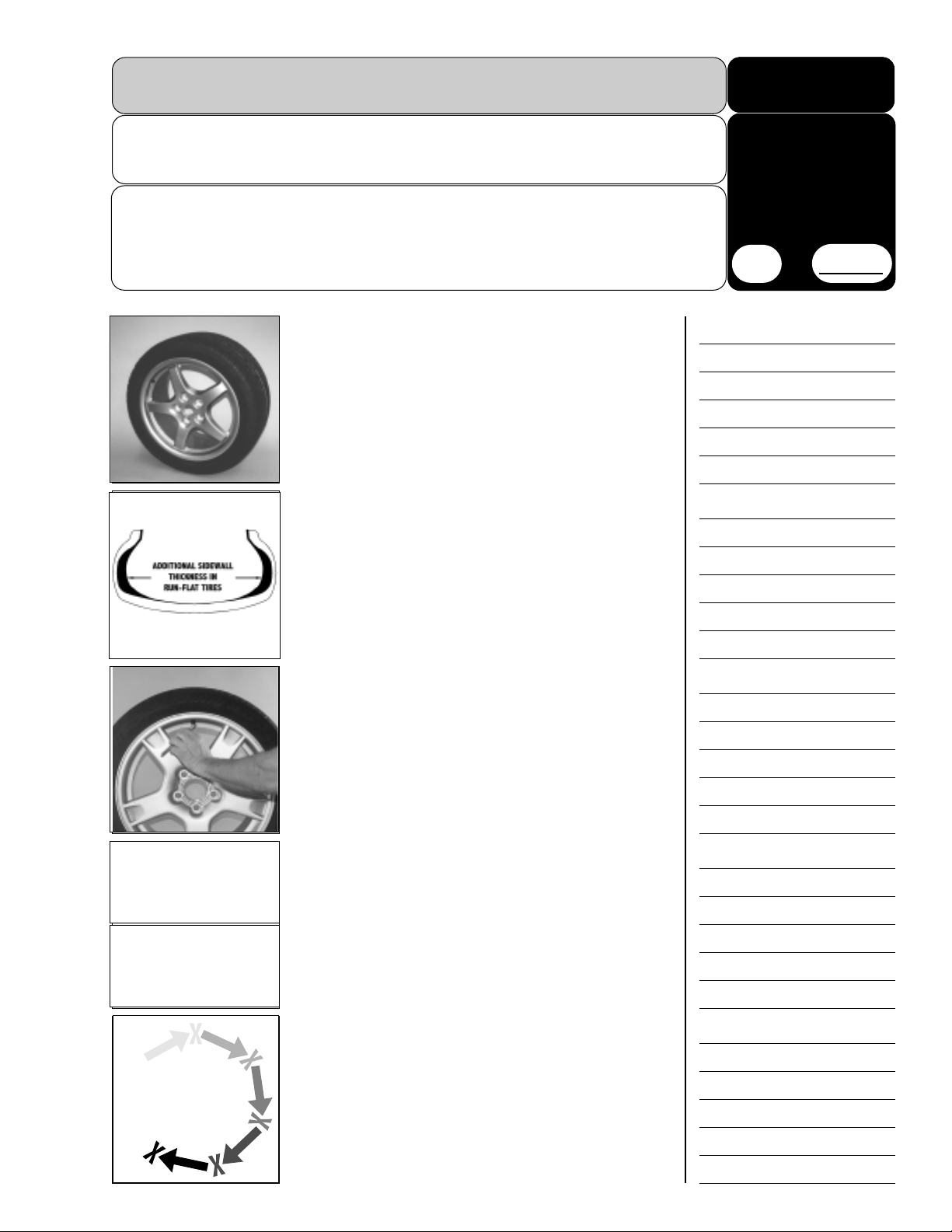
What is the difference in these new tires?
These tires are manufactured with exceptionally stiff sidewalls. These stiff sidewalls are designed to support the
wheel for limited periods of time without air pressure inside
the tire. Of course, stiffening the sidewalls to this degree creates problems for the wheel service technician.
How can I tell when the tire is flat?
Because the stiff sidewalls support the wheel in a drivable
posture even without air pressure, it is nearly impossible to
tell when this type of tire “goes soft.” Regular verification of
air pressure inside the tire is critical. Tire manufacturers are
required to install low pressure sensors on the wheels
(inside the tires) to provide electronic notification of low tire
pressure. These sensors transmit their low pressure warnings to a remote readout inside the vehicle.
This low pressure system is available on some new cars, and
will be available on even more models in the near future.
Today, customers can purchase an aftermarket system and
have it installed on their current vehicle. These systems use
either a valve-stem mounted sensor (O.E.M. only), or a sensor that straps onto the wheel (aftermarket & O.E.M.).
How is this type of tire serviced?
As any tire service technician can tell you, the stiffer the sidewall,
the tougher the tire changing. These new tires are so exceptionally stiff that they require special handling. This special handling
is not only to ease installation and prevent any damage to these
expensive tires, but to help prevent damage to the wheel and the
tire changing equipment. These tires require extra time and
patience to service and to prevent injury to the tire technician. Be
prepared to take your time and not rush the procedures..
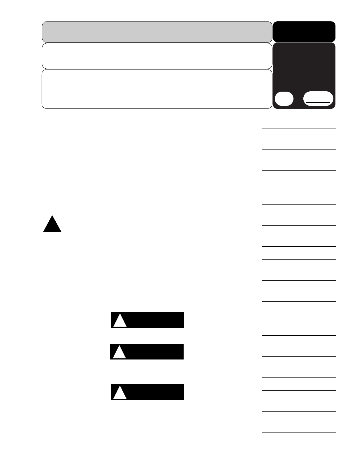
Rotate
Pause
Rotate
Overview
A–1
15
min
Stop Time
A
Page 10
A–2
Overview
These tires also require the tire service technician to be
extra cautious. In every case, there will be a low pressure
sensor of some type installed on the wheel. When standard
tire changing procedures are used on these tires the sensors
will be damaged. If not properly serviced, these sensors are
easily damaged and expensive to replace. Knowing the
proper method of changing a tire on a wheel equipped with
a sensor, and how the sensors themselves are installed, will
save the technician valuable time and resources and avoid
headaches and frustration.
Before you begin, take a good look at the tire and wheel.
There are things that the technician may take for granted
when changing standard tires that can have a dramatic
effect when changing these new tires. For example: on steel
wheels, watch for curb damage on the wheel rim flange that
is rough or sharp. The beads on these tires are pulled tightly
across this flange, and rough, sharp edges can seriously
damage the beads.
The tire service technician will also need to spend increased
time cleaning and polishing the wheel. These tires are very
inflexible, and will pull and slide against the wheel surfaces
much more than a standard tire. Keeping the wheel clean
and polished smooth will reduce friction and allow the tire to
move easier during the mounting and bead sealing process.
These tires made their debut on specialty vehicles like the
Corvette. Because of their “high performance” nature, these
tires are, in many cases, position–and directional–specific.
This means that they may be designed to roll in one direction
only, or to be placed in a front or rear position only. Or, in
some cases, they are totally position-specific, designed for
placement as right front, left rear, etc. This information is
included on the sidewall of the tire. The technician needs to
be aware of these specifics to ensure that tires are properly
mounted and positioned.
Many alloy wheels today are location-specific as well.
These wheels may have additional offsets to compensate for
brakes or other suspension requirements. This information is
usually included on the inside of the wheel. The technician
must also be aware of “reverse mount” wheels–where the
drop center (or short side of the wheel) is toward the inner
plane of the wheel instead of outer. Tires are always mounted from the short side, so reverse mount wheels will be
mounted to the tire changer “upside down” from
normal–with the inside of the wheel facing upwards.
Safe tire inflation is of the utmost importance.
These new tires are much tougher to bead seat and inflate.
Because they are so stiff, a bead seating pressure that
exceeds 40 PSI may be required. For this reason, a safety
cage must be used for bead seating and inflation of
EMT/RunFlat Tires. Read and follow ALL the safety instruc-
tions provided in this publication and your tire changer manual.
This completes Section A.
Page 11
The Objective of this Section:
To clearly identify the safety issues related to tire service and inflation procedures.
Safety Issues Related to this Section:
• Operator Protective Equipment.
• Definitions of Hazard Levels.
• ALWAYS use a safety cage for bead seating and inflation of EMT/RunFlat Tires.
• NEVER inflate tire above manufacturer’s recommended pressure after bead is seated.
This instruction manual is intended to supplement the Operating Instructions manual provided with your tire changer. Read and understand the entire manual before servicing any
tire or wheel. Read and follow all the CAUTION, WARNING, and DANGER notations in the
manual as they apply to these instructions as well. This manual is intended to act only as
an information supplement, and does NOT replace your Operating Instructions manual.
These exceptionally stiff sidewall tires use super-reinforced sidewalls and stiffer composition materials. It is very difficult to mount and demount. These tires may be used on
expensive custom wheels that are easily scratched or damaged. These tire/wheel assemblies will include a low-pressure sensor affixed to the inside of the wheel–either as a strap
on addition or a one-piece valve stem sensor. The operator must use extra care and caution when working with these tire/wheel/sensor combinations to avoid costly damage to
any of the individual components. These special combinations require changes to the
standard mount/demount instructions for your tire changer.
OPERATOR PROTECTIVE EQUIPMENT
Personal protective equipment helps make tire changing safer. However, equip-
ment does not take the place of safe operating practices. Always wear durable
work clothing during tire service activity. Shop aprons or shop coats may also
be worn, however loose fitting clothing should be avoided. Tight fitting leather gloves are
recommended to protect operator’s hands when handling worn tires and wheels. Sturdy
leather work shoes with steel toes and oil resistant soles should be used by tire service
personnel to help prevent injury in typical shop activities. Eye protection is essential during tire service activity. Safety glasses with side shields, goggles, or face shields are
acceptable. Back belts provide support during lifting activities and are also helpful in providing operator protection. Consideration should also be given to the use of hearing protection if tire service activity is performed in an enclosed area, or if noise levels are high.
Definitions of Hazard Levels
Identify the hazard levels used in this manual with the following definitions and signal
words:
Watch for this symbol:
It Means: Immediate hazards which will result in severe personal injury or death.
Watch for this symbol:
It Means: Hazards or unsafe practices which could result in severe personal injury or death.
Watch for this symbol:
It Means:Hazards or unsafe
practices which may result in minor personal injury or product or property damage.
READ AND UNDERSTAND THESE INSTRUCTIONS BEFORE BEGINNING. KEEP THESE
INSTRUCTIONS IN A BINDER NEAR THE MACHINE FOR REFERENCE BY SUPERVISORS
AND OPERATORS.
Safety
B–1
15
min
Stop Time
B
!
DANGER
!
WARNING
!
CAUTION
!
Page 12
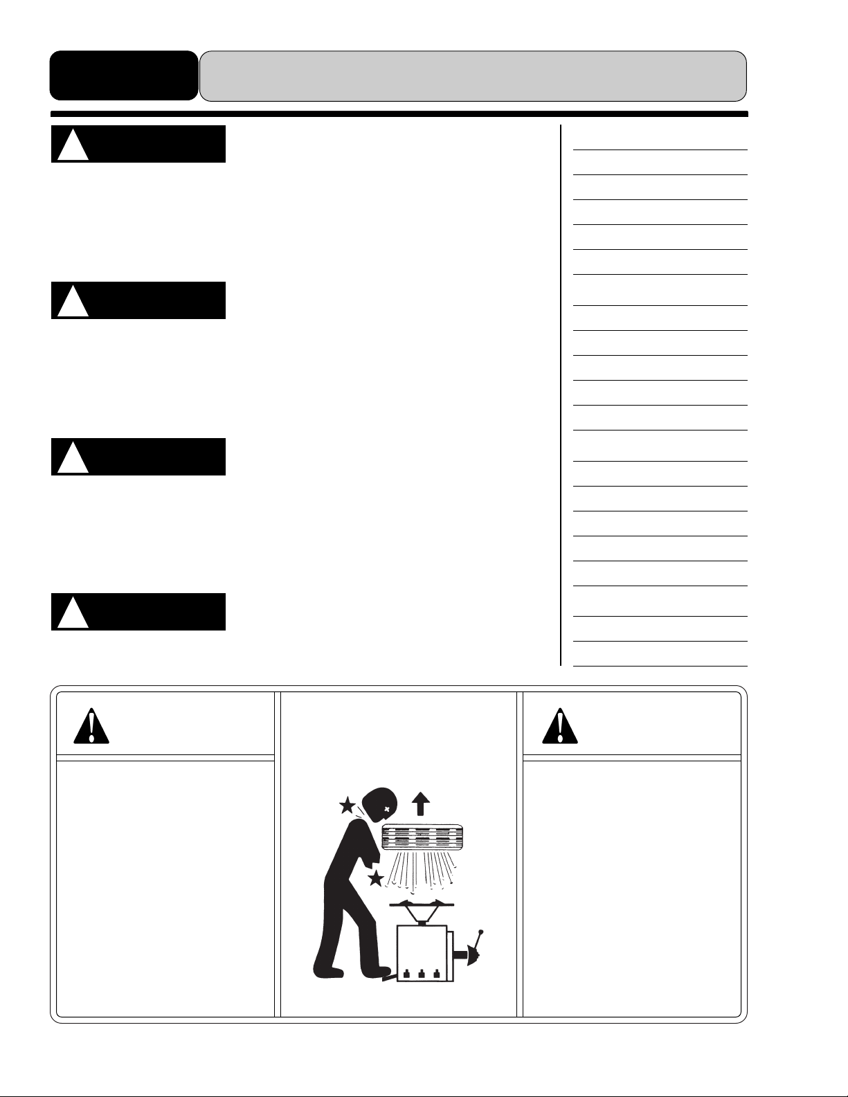
DANGER
Explosion Hazard
Never inflate
tire above
manufacturer’s
recommended
pressure after bead
is seated.
DANGER
Explosion Hazard
A safety cage must be
used for bead seating
and inflation of
EMT/RunFlat Tires.
Never exceed 80 PSI to
seat beads on
EMT/RunFlat Tires.
B–2
Safety
The low-pressure sensors used on these tire/wheel
assemblies are very expensive to replace. Do NOT use
the bead loosener where it may come in direct contact
with the sensor. Do NOT use full strokes of the bead loosener to avoid pushing the tire bead into the sensor. ALWAYS
check sensor position before starting any procedure.
Failure to follow DANGER, WARNING, and CAUTION
instructions may lead to serious personal injury or death
to operator or bystander or damage to property. Do not
operate this machine until you read and understand all the
DANGER, WARNING and CAUTION notations in this manual.
This tire changer may operate differently from machines
you have previously operated. Practice with a regular
steel wheel and tire combination to familiarize yourself
with the machine’s operation and function.
The tire changer must be properly operated and main-
tained to help avoid accidents that could damage the
unit and injure the operator or bystanders.
CAUTION
!
CAUTION
!
WARNING
!
CAUTION
!
This completes Section B.
Page 13
The Objective of this Section:
To provide a basic list of the tools and equipment that will be required to change exceptionally
stiff sidewall tires.
Safety Issues Related to this Section:
This manual is intended to supplement the Operator’s Manual provided with your tire changer
only and is not meant as a replacement. ALL safety issues contained in your original Operator’s
Manual remain in effect when changing this type of tire. The safety information contained in this
manual is to be used in addition to the safety information in your Operator’s Manual.
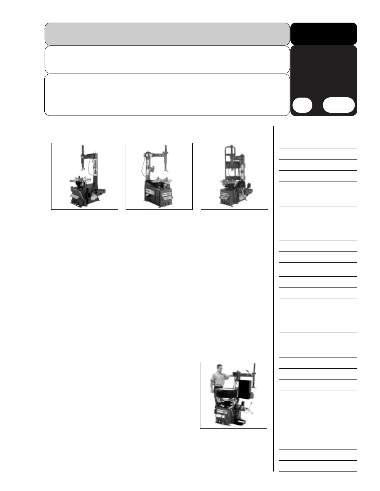
This manual is written based on the use of COATS Rim Clamp®Tire Changers. This includes
models 5030, 5050, 5060, 5065, 6060, and 6065.
Equipment and Tool list:
• Safety Glasses
• Tire Lubricant (slow drying)
• Lube Swab
• Tire Marking Crayon
• Plastic booties (for metal duckheads)
• Drop Center Tool
• Lift Tool
• Shop Towels
• Air Pressure Gauge
• Valve Core Tool
• Valve Stems
• Valve Stem Puller
• Nut Driver (5/16 for strap-type sensor)
• Wrench (7/16 for valve-type sensor)
• Tin Snips
• Air Hose with Remote Valve and Clip On Chuck
• Safety Cage (for inflation)
• Inch Pound Torque Wrench
This completes Section C.
Tools & Equipment
C–1
10
min
Stop Time
C
Page 14

Page 15
The Objective of this Section:
To identify the safe and proper loosening of both inner and outer tire beads.
Safety Issues Related to this Section:
• ALWAYS wear eye protection during tire service activity.
• ALWAYS wear durable work clothing (i.e.; tight-fitting leather gloves, steel-toed shoes, back belts).
• NEVER wear loose fitting clothing or articles, jewelry, or long hair.
• NEVER smoke or have open flames or other ignition sources in or near tire changing area.
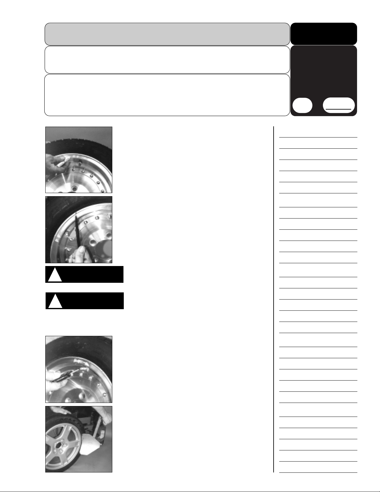
1
Use a crayon to mark both the tire and wheel with their
location on the vehicle (i.e.; RF, LR, etc.). Check the sidewall of the tire for any rotation and position indicators.
Remember that some low-pressure sensors are locationspecific as well. Note any offsets that may exist between the
front and rear wheels, or any difference in tire width.
Marking the tire and wheel will help you reinstall them in the
correct location later.
2
Inspect the wheel and tire for damage. Pay close atten-
tion to the rim flange–nicks or burrs here may interfere
with the mounting process or damage the tire bead. Make a
note of any damage found, and review with the customer
before continuing.
Safety glasses must be worn at all times. Air is released
from the tire with sufficient force to propel dirt and
debris into the eyes.
Never smoke or have open flames and/or other ignition
sources in or near tire changing area. A flammable gas
may have been used to pressurize the tire, and severe
personal injury or death could result.
3
Remove the valve core and allow the tire to completely
deflate. Remove all wheel weights from the wheel at this
time.
4
Roll the tire and wheel into position at the bead loosener,
with the top bead facing outward and the wheel seated
firmly against the rubber pads. The valve stem should be
positioned towards the top of the bead loosener shoe. This
position works best for wheels with existing pressure sensors, and those wheels with asymmetrical safety humps..
Bead Loosening
D–1
10
min
Stop Time
D
CAUTION
!
WARNING
!
Page 16

D–2
Bead Loosening
5
Loosen the upper bead, making sure not to over com-
press the tire. Allow the shoe to move the tire to a position just past the safety hump and then release. Do not push
the tire any farther into the wheel.
The tire in the photo is compressed too far (as represented
by the white arrow). The black arrow and line represent the
point to which the tire should be compressed.
6
Turn the tire and wheel around and reposition to loosen
the lower bead. Position the valve stem towards the top
of the bead loosener shoe.
Do not over compress the tire. Allow the shoe to move the
tire to a position just past the safety hump and then release.
Loosening the lower bead may require multiple attempts at
different locations around the wheel. Always make the first
attempt with the valve stem positioned as shown here, then
move to other locations.
7
Wheels with an asymmetrical safety hump can be bead
loosened only at the valve stem. This is true for both
upper and lower beads. Note the difference in the safety
hump at the valve stem and at a position 180° away from the
valve stem.
8
Rotate the tire changer table top to position the clamps
at 12, 3, 6, and 9 o’clock positions (when viewed from the
front of the machine).Move the clamps out to their fully
extended position.
9A
Lift the tire and wheel onto the table top…
9B
…and position the wheel rim into the rear clamp.
Lower the wheel and move the clamps into position
to clamp the wheel externally. Always clamp the wheel
externally when mounting and demounting EMT tires.
This completes Section D
.
!
Page 17

The Objective of this Section:
To demonstrate the safe and proper demounting of exceptionally stiff sidewall tires on wheels
with a valve-type low-pressure sensor installed. To demonstrate the use of a metal duckhead.
Safety Issues Related to this Section:
• ALWAYS wear eye protection during tire service activity.
• ALWAYS wear durable work clothing (i.e.; tight-fitting leather gloves, steel-toed shoes, back belts).
• NEVER wear loose fitting clothing or articles, jewelry, or long hair.
• ALWAYS deflate the tire completely and loosen both beads before beginning the demount procedure.
1
Lubricate the upper tire bead and the wheel liberally
with a slow-drying tire lubricant. Use the lift bar to help
push the sidewall down and provide easier access to the
bead and wheel. Rotate the wheel and lubricate the entire
circumference.
1A
Make sure to adequately lubricate the horizontal
wheel surface above the drop center and below the
safety hump. This will help the tire bead slide into the drop
center of the wheel opposite the duckhead.
2
Move the swing arm into position. Adjust the duckhead
so that it is 1⁄8
to
3
⁄16
inch away from the wheel.
NOTE: Always use a plastic bootie on metal duckheads. This
will help prevent damage to the wheel.
3
Rotate the wheel until the valve stem is under the rear
portion of the duckhead.
Position a drop center tool directly across from the duckhead to help the tire slide into the drop center as the bead is
lifted over the duckhead. If a drop center tool is not available,
a valve stem can be used as an aid. Insert it between the tire
and wheel across from the duckhead.
Lubricate the end of the lift bar. Insert the lift bar between the
tire and wheel, immediately next to the duckhead.
4
Begin rotating the lift bar down over the duckhead to pull
the tire bead up and over the duckhead. Move the tool
slowly and do not rush.
Remove the drop center tool (or other aid) as the bead slides
into the drop center of the wheel.
Demounting–Valve-Type Sensor
E–1
10
min
Stop Time
E
Page 18

E–2
Demounting–Valve-Type Sensor
5
Continue to pull the lift bar down and lift the tire bead
onto the duckhead. Pull the tool down slowly to allow the
tire bead to move into position without damaging the bead.
6
Once the upper bead is in position on the duckhead,
carefully remove the lift bar.
NOTE: Leaving the lift bar in place increases the arc of the
tire bead over the duckhead, thereby increasing the resistance. Removing the tool lessens the resistance and helps
prevent damage to the bead.
7
Begin removing the bead by rotating the wheel a short
distance–3 to 4 inches only–and stopping. Allow the
bead and sidewall to relax. Rotate the wheel again for a
short distance then stop to allow the tire to relax. Continue in
this manner until the upper bead is free of the wheel.
8
To remove the lower bead, begin by rotating the wheel
until the sensor/valve stem is once again under the rear
portion of the duck head. Lift the tire and carefully guide the
lower bead into position above the sensor.
NOTE: Positioning the sensor under the duckhead allows the
tire bead to slide into the drop center on the opposite side of
the wheel without interference.
9
Use the lift bar to lift the lower bead over the duck head.
Begin rotating the wheel very slowly, using the lift bar to
help keep the lower bead above the wheel.
NOTE: It may be advisable to place a shop rag between the
lift bar and the wheel to prevent damaging the wheel surface.
10
Continue rotating the wheel very slowly until the
lower bead is free of the wheel. Use the lift bar to help
keep the demounted bead above the wheel.
This completes Section E
.
Rotate
Pause
Rotate
Page 19

The Objective of this Section:
To identify the component parts of a valve-type sensor and the proper installation of the sensor
assembly.
Safety Issues Related to this Section:
• Protective eyewear must be worn at all times.
1
Identify the various parts that make up the valve-type
sensor: sensor with metal valve stem; O-ring;
nut, valve cap.
Inspect the O-ring carefully. If it is damaged, replace it with
a new ring before proceeding.
NOTE: Some sensors are location-specific (i.e.; front left,
right rear, etc.). Always install the correct sensor on the correct wheel so that the sensor is in the correct position.
2
Inspect the valve mounting hole. Be sure to inspect both
sides of the hole. Make sure it is clean and free of burrs
and nicks that may keep the valve from sealing properly
around the hole. Wipe away any dirt or debris.
3
Verify that air flows freely through the valve. Make sure
the valve core is installed, then apply air pressure to the
valve. Air should flow freely through the valve and sensor,
escaping through the air pressure port in the sensor.
4
Install the sensor by inserting the valve stem through the
mounting hole in the wheel. The sensor should lay back
towards the wheel with the O-ring in full contact with the
inner wheel surface. If a washer is used, place it over the
valve stem and against the outer wheel surface. Screw the
nut down onto the valve stem and finger tighten only. Use a
torque wrench to tighten the nut down to 90-105 inch pounds
(or to the sensor manufacturer’s specifications).
5
When removing a valve-type sensor, use care to avoid
damaging the sensor. Hold on to the sensor to keep it
from falling off the wheel once the nut is removed.
If the sensor is location-specific, make sure it is reinstalled
on the proper wheel.
This completes Section F.
Sensor Inspection & Installation–Valve-Type
F–1
10
min
Stop Time
F
Page 20

Page 21

The Objective of this Section:
To demonstrate the safe and proper mounting of exceptionally stiff sidewall tires on wheels with
a valve-type low-pressure sensors installed. To demonstrate the use of a metal duckhead.
Safety Issues Related to this Section:
• ALWAYS wear eye protection during tire service activity.
• ALWAYS wear durable work clothing (i.e.; tight-fitting leather gloves, steel-toed shoes, back belts).
• NEVER wear loose fitting clothing or articles, jewelry, or long hair.
1
Clean and polish the wheel. Check for any burrs or dam-
age to the wheel that might damage the tire during the
mounting process. Stiff sidewall tires of this type are exceptionally snug-fitting, and a clean, polished surface will
reduce friction and aid in the mounting and bead seating
process.
NOTE: Always clamp the wheel externally. This prevents the
wheel from moving upwards during the mounting process.
2
Lubricate the entire surface of the wheel liberally with a
slow-drying lubricant. Pay special attention to the bead
seat area, the safety humps, and the drop center.
3
Lubricate the lower tire bead.
NOTE: Pay strict attention to any specific tire location information on the wheel. The tire may have been marked earlier
with a location and/or rotation direction. The imprinting on
the tire sidewall may also give you specific location and
directional information. Remember that the low-pressure
sensor may also be location specific. Make sure you are
mounting the correct tire on the correct wheel.
4
Rotate the tabletop so that the valve stem and pressure
sensor are at the 6 o’clock position.
5
Position the tire over the wheel, with the lower bead
resting on the back of the duckhead. Position the duckhead so that it is 1⁄8 to 3⁄16 inch away from the wheel.
Remember to use the plastic bootie on metal duckheads.
Hold the tire down with the lower bead in the drop center
and rotate the wheel slowly. The lower bead should be
eased over the wheel slowly and carefully, giving the sidewall time to relax. Hold the tire so that the bead stays in the
drop center.
Mounting–Valve-Type Sensor
G–1
10
min
Stop Time
G
Page 22

G–2
Mounting–Valve-Type Sensor
6
Once the lower bead is mounted, rotate the table top
until the valve stem and pressure sensor are once again
in the 6 o’clock position.
Lubricate the upper bead liberally. Apply lubricant to both the
edge of the tire bead and the underside of the bead.
Adequate lubrication is vital to the upper bead mounting
process.
7
Position the upper bead over the duckhead. Put the tip of
the lift tool under the wheel rim flange and push the bar
down to hold the upper bead below the wheel and duckhead.
Use a shop towel on the lift tool to avoid damaging the wheel.
8
Rotate the wheel a short distance–only 3 to 4 inch-
es–and stop. Continue to hold the bead in the drop center with the lift bar, or place a drop center tool on the wheel.
Remember that stiff sidewall tires are difficult to mount. The
top bead is always more difficult to work with because the
tire cannot be angled across the drop center and rim flange
as easily as the lower bead.
9
Continue rotating the wheel, moving only a few inches
and then stopping.
Continue to hold the bead in the drop center with the lift bar
or the drop center tool. When the bar or the drop center tool
reach the 10 o’clock position, remove them. Continuing with
either tool in place may cause them to be forcefully ejected
from the wheel.
Continue rotating the wheel until the upper bead is fully mounted.
This completes Section G.
Page 23

The Objective of this Section:
To demonstrate the safe and proper bead seal, bead seat, and inflation of exceptionally stiff
sidewall tires.
Safety Issues Related to this Section:
• ALWAYS wear eye protection during tire service activity.
• ALWAYS wear durable work clothing (i.e.; tight-fitting leather gloves, steel-toed shoes, back belts).
• NEVER wear loose fitting clothing or articles, jewelry, or long hair.
• NEVER exceed the maximum safe air pressure during inflation process.
Tire inflation is performed in three (3) steps: bead seal, beat
seat, and inflation. These steps are explained in detail on
page H–5. Read the explanation of each step and understand
them thoroughly before proceeding.
Make sure the tire changer inflation gauge is operational. Accurate tire pressure readings are important to
safe tire inflation. Do not use a hand held gauge as personal injury could result.
If the wheel has been clamped from the outside for tire
mounting, release the clamps, lift the tire, and move the
clamps to the center of the tabletop.
If the tire/wheel has a diameter larger than 14 inches and
it is difficult to bead seal, the clamps should be moved to
the center of the tabletop for the bead seal operation.
Tire failure under pressure is hazardous. The tire changer
is not intended to be a safety device to contain exploding
tires, tubes, wheels, or bead sealing equipment. Inspect
tire and wheel carefully for match, wear, or defects before
mounting. Always use approved tire bead lubricant during
mounting and inflation.
The inflation pedal controls the flow of air through the inflation hose.
NOTE: The clip-on chuck on the end of the hose should always
be an open style with all parts in proper working order.
Position 1–At Rest–With the inflation hose attached to the
tire valve and the pedal in this position, the air gauge will
register the air pressure in the tire. Whenever the operator’s
foot is removed from the pedal, it will return to this position.
Position 2–Tire Inflation–This is the first activated position.
With the inflation hose attached to the tire valve and the
pedal in this position, line pressure is allowed to flow through
the valve and into the tire for inflation. Tire pressure is not
indicated on the gauge in this position.
Position 3–Bead Sealing–This is the second and last activated position. With the inflation hose attached to the tire valve
and the pedal in this position, line pressure is allowed to flow
through the valve and to the air-flate bead seal jets on the
table top for bead sealing.
Use Position 3 for bead sealing only. Do not use position
3 without a tire and wheel positioned on the tabletop.
Dirt and debris could be blown into the air with enough
force to injure the operator or bystanders. Do not use position 3 to inflate a tire.
Inflation
H–1
15
min
Stop Time
H
CAUTION
!
CAUTION
!
CAUTION
!
DANGER
!
CAUTION
!
Position 1
Tire Pressure
Position 2
Tire Inflation
Position 3
Bead Seal
Inflation Pedal Positions
Page 24

H–2
Inflation
IMPORTANT: Many tire changers are equipped with a pressure limiter to assist the operator with proper tire inflation.
When the inflation pedal is held in position 2, the pressure
limiter cycles the machine between position 2 (inflation) and
position 1 (at rest, no air flow). This cycling helps to prevent
over inflation of the tire. Tires can still be over inflated and
explode with the use of the pressure limiter if all of the
instructions in this manual are not followed completely. The
pressure limiter will keep most car and light truck tires from
inflating beyond 60 PSI (smaller tires may reach higher pres-
sures). It is the operator’s responsibility to follow all instructions and to control inflation pressure as specified in these
instructions. Check the function of the pressure limiter regularly and maintain it according to any provided service
instructions for safe and proper operation. Tires that require
inflation beyond 60 PSI must be inflated in a safety cage.
Bead Sealing
1
Bead sealing is typically not a problem when inflating
EMT/RunFlat Tires. Connect the inflation hose to the tire
valve stem. Hold the tire up against the upper edge of the
wheel. Be sure the top bead of the tire is over the bottom of
the valve stem.
2
Depress the inflation pedal to position 2 and hold about
1 second to begin air flow, then depress the pedal to
position 3 and hold very briefly–less than 1 full second. The
blast of air from the jets will expand the tire and seal the
beads.
3
Release the inflation pedal and allow it to return to posi-
tion 1. Verify that both beads are completely sealed to the
wheel. Repeat these steps if the beads have not been sealed.
NOTE: If the tire and wheel are properly lubricated and the
operator cannot achieve bead seal after 3 or 4 attempts, the
valve core may be removed from the valve stem to allow
more air into the tire to assist with bead seal.
Page 25

Inflation
H–3
Bead Seating–Safety Cage for EMT/RunFlat Tires
Operator should keep hands, arms, and entire body away
from the tire during bead seat and inflation procedures.
Do not stand over the tire as personal injury could result.
Always use a safety cage to bead seat and inflate
EMT/RunFlat tires. Never exceed 80 PSI to seat beads on
EMT/RunFlat tires. If operator is unable to obtain bead
seat, something is wrong. Deflate the tire completely,
inspect both the tire and wheel, correct any problems found,
relubricate both tire beads, and reattempt bead seal and
bead seat procedures. Follow all safety instructions in this
manual and on the machine.
You must inspect all wheels and tires prior to inflation
for condition or improperly matched wheels/tires.
Damaged or improperly matched wheels/tires may fail
upon inflation. Portions of a damaged or improperly
matched wheel/tire may not be restrained by a tire safety
cage resulting in injury or death.
1
Once tire pressure is indicated on the air gauge, remove
the tire/wheel from the tire changer, reinstall the valve
core (if it was removed), and place the assembly in an
approved safety cage.
Stand back during bead seat. Check the pressure frequently.
Keep hands, arms, and entire body away from safety cage
and tire during this procedure.
Tire beads should move outward and “pop” into their bead
seat position. If this does not happen, a problem exists.
Investigate carefully.
Check tire pressure frequently. Never exceed 80 PSI
while seating beads on EMT/RunFlat tires. Once seated,
never exceed tire manufacturer’s recommended air
pressure. Tires can explode, especially if they are inflated
beyond their limits. At all pressure levels when inflating
through the valve stem, keep hands, arms, and entire body
away from inflating tire. An unrestrained exploding tire,
wheel, or bead sealing equipment may propel upward and
outward with sufficient force to cause serious injury or
death to operator or bystander.
2
Use an air hose equipped with a remote pressure gauge and
valve. The air hose should be of sufficient length to allow the
operator to move a safe distance away from the cage.
Stay out of the trajectory as indicated by dotted area.
3
Apply air pressure to the tire in short bursts, checking
the air pressure in the tire in between bursts. Exercise
caution as the air pressure increases. Attempt to seat the
beads with minimum air pressure.
Once the beads “pop” into their seated position, stop the air
flow to the tire immediately.
WARNING
!
WARNING
!
WARNING
!
WARNING
!
WARNING
!
Page 26

H–4
Inflation
INFLATION–Safety Cage for EMT/RunFlat Tires.
NEVER exceed the tire manufacturer’s recommended air
pressure. Tires can explode, especially if inflated
beyond these limits. Keep hands, arms, and entire body
back from the inflating tire. Avoid distraction during inflation. Check the tire pressure frequently to avoid over inflation. Excessive pressure can cause tires to explode, causing serious injury or death to the operator or bystander.
1
Verify that both beads are fully seated. When both beads
are seated, the tire is ready for inflation.
2
Replace the valve core (if removed). Leave the tire
inside the safety cage for inflation.
3
Verify the air pressure inside the tire. If the pressure
exceeds the manufacturer’s recommended pressure,
bleed off the excess pressure until the correct level is
reached.
If the pressure is below the recommended level, attach the
air hose with the remote gauge to the valve stem. Stand
safely away from the cage. Add air pressure to the tire in
short intervals, checking the increasing pressure frequently.
Do not over inflate the tire.
DANGER
!
Page 27

Mis-Matched Tires and Wheels–NEVER attempt to mount and inflate mis-matched tires and wheels.
Mis-matched tires and wheel combinations can explode, causing personal injury or death
to operator and bystanders. For safety reasons, do not attempt to mount and inflate mismatched tires and wheels.
Inflation
H–5
This completes Section H.
Bead Sealing–A 140 PSI air blast from the tabletop jets creates an air
curtain to aid in bead sealing. NEVER exceed 10 PSI in the tire during
bead sealing. The tire will contain about 1⁄2 to 2 PSI when bead seal is
obtained.
Bead Seating–Bead seating usually occurs on the long tapered side of
the wheel first and the shorter side last. Bead seating will usually
require at least 7 PSI in the tire. If the tire is in an approved safety cage,
80 PSI is the maximum safe pressure at this stage, regardless of operating pressure.
Most European import cars and many aftermarket alloy wheels are very
tight and may be difficult to bead seat. Also note that asymmetric hump
and run flat tires are extremely difficult to bead seat. Follow tire manufacturer’s recommended procedure for bead seating.
Inflation–After the beads are seated, the tire is inflated. DO NOT inflate
the tire above the manufacturer’s recommended pressure as stamped
on the tire sidewall. The typical inflation pressure for automobile tires is
between 24 and 45 PSI. Light truck inflation pressure typically covers a
wider range.
DANGER
!
A safety cage must be used for bead seating and inflation of EMT/RunFlat tires.
Page 28

Page 29

Student Name ………………………………………………………………
Signature ………………………………………………… Date……………
Instructor ……………………………………………………………………
Signature for completion of Test ………………………… Date…………
Test for Performance Certification for EMT
I–1
15
min
Stop Time
I
S = Successful Demonstration of Ability N = Needs more Practice
Bead Loosening
1. Mark both tire and wheel with their location
on the vehicle (i.e., LF, LR, LR, RR)
2. Inspect wheel and tire for damage.
3. Remove valve core and allow the tire to
deflate completely. Remove all wheel weights
from the wheel.
4. Roll the tire and wheel into position for bead
loosening, positioning the valve stem near the
top of the bead loosening shoe.
5. Loosen the upper bead without compressing
too far.
6. Turn wheel and tire around and reposition to
loosen the lower bead.
7. Rotate the tire changer table top to position
the clamps at 12, 3, 6, and 9 o’clock and extend
clamps out.
8. Lift the tire and wheel onto the table top and
position into rear clamp. Lower wheel and
clamp wheel externally.
Demounting
–(
Metal Duckhead) Valve-Type Sensor
1. Lubricate the upper tire bead and wheel lib-
erally.
2. Move swing arm into position and adjust so
that the duckhead is 1/8 inch to 3/16 inch away
from the wheel.
3. Rotate wheel to position the valve at the rear
of the duckhead. Position a drop center tool
directly across from the duckhead. Lube the
end of the lift tool and insert it between the
wheel and tire at the duckhead.
4. Slowly rotate the lift tool over the duckhead
towards the wheel and remove the drop center
tool as the tire bead slides into the drop center
of the wheel.
5. Continue to rotate lift tool until the tire bead
is on the duckhead.
6. Once the upper bead is in position, carefully
remove the lift bar.
7. Remove the upper bead with short table
rotations–3 to 4 inches–until the upper bead is
removed from the rim.
8. Position the sensor/valve once again at the
rear portion of the duckhead.
9. Use lift tool to lift lower bead over the duckhead. Use a shop rag between the lift tool and
wheel as you begin to rotate the wheel slowly.
10. Continue rotating slowly until the lower
bead is free from wheel.
S N
S N
Page 30

Test for Performance Certification for EMT
I–2
S = Successful Demonstration of Ability N = Needs more Practice
Sensor Installation–Valve-Type
1. Identify the various parts that make up the
valve-type sensor.
2. Inspect the valve mounting hole.
3. Install the sensor by inserting the valve stem
through the mounting hole in the wheel.
4. Once nut is installed, torque to 90-105 inch
pounds to prevent leaking.
Mounting
–(
Metal Duckhead) Valve-Type Sensor
1. Clean and polish the wheel. Check for any
burrs or damage to the wheel that might damage the tire during the mounting process.
2. Lubricate the wheel.
3. Lubricate the lower tire bead.
4. Rotate the tabletop so that the valve stem
and pressure sensor are at the 6 o’clock position.
5. Position the tire over the wheel, with the
lower bead resting on the back of the duckhead. Position the duckhead so that it is
1
⁄8 to 3⁄16
inch away from the wheel. Remember to use
the plastic bootie on metal duckheads.
6. Hold the tire down with the lower bead in the
drop center and rotate the wheel slowly. The
lower bead should be eased over the wheel
slowly and carefully, giving the sidewall time to
relax. Hold the tire so that the bead stays in the
drop center.
7. Once the lower bead is mounted, rotate the
table top until the valve stem and pressure
sensor are once again in the 6 o’clock position.
8. Lubricate the upper bead liberally. Apply
lubricant to both the edge of the tire bead and
the underside of the bead. Adequate lubrication is vital to the upper bead mounting
process.
9. Position the upper bead over the duckhead.
Put the tip of the lift tool under the wheel rim
flange and push the bar down to hold the upper
bead below the wheel and duckhead. Use a
shop towel on the lift tool to avoid damaging
the wheel.
10. Rotate the wheel a short distance–only 3 to
4 inches–and stop. Continue to hold the bead in
the drop center with the lift bar, or place a drop
center tool on the wheel.
11. Continue rotating the wheel using 3 to 4
inch jogs until the upper bead is fully mounted.
S N
S N
Page 31

Test for Performance Certification for EMT
I–3
S = Successful Demonstration of Ability N = Needs more Practice
Inflation (1-4 For bead sealing only)
1. Connect the inflation hose to the tire valve
stem. Hold the tire up against the upper edge
of the wheel. Be sure the top bead of the tire is
over the bottom of the valve stem.
2. Depress the inflation pedal to position 2 and
hold about 1 second to begin air flow, then
depress the pedal to position 3 and hold very
briefly–less than 1 full second to seal the
beads.
3. Release the inflation pedal and allow it to
return to position 1. Verify that both beads are
completely sealed to the wheel.
4. Once tire pressure is indicated on the air
gauge (with the inflation pedal in position 1 and
foot removed from the pedal), unclamp the
wheel from the clamps.
5. Remove the tire/wheel from the tire changer,
reinstall the valve core (if it was removed), and
place the assembly in an approved safety
cage.
6. Use an air hose equipped with a remote
pressure gauge and valve.
7. Apply air pressure to the tire in short bursts,
checking the air pressure in the tire in between
bursts. Attempt to seat the beads without pressurizing the tire any more than necessary.
Once the beads “pop” into their seated position, stop the air flow to the tire immediately.
8. Verify that both beads are fully seated. When
both beads are seated, the tire is ready for
inflation. Leave the tire in the safety cage for
inflation.
9. Adjust, per vehicle specifications, the air
pressure inside the tire.
All EMT/RunFlat inflation must be completed in a
safety cage except for bead sealing. Bead sealing is typically not a problem when inflating
EMT/RunFlat tires.
S N
Page 32

Page 33

The Objective of this Section:
To demonstrate the safe and proper demounting of exceptionally stiff sidewall tires on wheels with
a low-pressure sensor strapped into the drop center. To demonstrate the use of a plastic duckhead.
Safety Issues Related to this Section:
• ALWAYS wear eye protection during tire service activity.
• ALWAYS wear durable work clothing (i.e.; tight-fitting leather gloves, steel-toed shoes, back belts).
• NEVER wear loose fitting clothing or articles, jewelry, or long hair.
• ALWAYS deflate the tire completely and loosen both beads before beginning the demount procedure.
1
Lubricate the upper tire bead and the wheel liberally
with a slow-drying tire lubricant. Use the lift bar to help
push the sidewall down and provide easier access to the
bead and wheel. Rotate the wheel and lubricate the entire
circumference.
1A
Make sure to adequately lubricate the horizontal
wheel surface above the drop center and below the
safety hump. This will help the tire bead slide out of the drop
center and off the wheel easier.
2
Move the swing arm into position. Adjust the duckhead
so that it rests against the wheel.
3
Rotate the wheel until the valve stem is opposite the
duckhead. Position the sensor under the rear portion of
the duckhead. This will allow the lift bar to be inserted with
out hitting the sensor.
Position a drop center tool directly across from the duckhead to help the tire slide into the drop center as the bead is
lifted over the duckhead. If a drop center tool is not available,
a valve stem can be used as an aid. Insert it between the tire
and wheel across from the duckhead.
Lubricate the end of the lift bar. Insert it between the tire and
wheel, under the front extension of the duckhead.
4
Begin rotating the lift bar down over the duckhead to pull
the tire bead up and over the duckhead. Move the tool
slowly and do not rush.
Remove the drop center tool (or other aid) as the bead slides
into the drop center of the wheel.
Demounting–Strap-Type Sensor
J–1
15
min
Stop Time
J
Page 34

J–2
Demounting–Strap-Type Sensor
5
Continue to pull the lift bar down and lift the tire bead
onto the duckhead. Pull the tool down slowly to allow the
tire bead to move into position without damaging the bead.
6
Hold the lift bar down against the wheel.
7
Rotate the wheel a short distance -3 to 4 inches only-
and stop. Allow the bead and sidewall to relax. Rotate
the wheel again for a short distance then stop to allow the
tire to relax. Continue in this manner until the upper bead is
free of the wheel.
8
Rotate the wheel until the sensor is once again under
the duck head. Lift the tire and carefully guide the lower
bead into position above the sensor.
9
Use the lift bar to lift the lower bead over the duck head.
Begin rotating the wheel very slowly, using the lift bar to
help keep the lower bead above the wheel.
NOTE: It may be advisable to place a shop rag between the
lift bar and the wheel to prevent damaging the wheel surface.
10
Continue rotating the wheel very slowly until the
lower bead is free of the wheel. Use the lift bar to help
keep the demounted bead above the wheel.
This completes Section J.
Rotate
Pause
Rotate
Page 35

The Objective of this Section:
To demonstrate the proper installation of a strap on sensor assembly.
Safety Issues Related to this Section:
• Protective eyewear must be worn at all times.
1
Locate the drop center on the wheel. The strap on sen-
sor should be positioned as low on the drop center as
possible (photo 2). Do not strap the sensor to the slanted portions of the wheel. The strap will come loose and the sensor
assembly will flop freely around the inside of the tire. Photo
1 shows a properly installed strap-type sensor.
Strap sensors are location specific. Be sure to match the
sensor location (as indicated on the sensor label) to the correct wheel location.
2
Lay the strap around the drop center and overlap the
ends. Trim the strap down so that it overlaps itself by 2 to
3 inches.
The photo shows the correct mounting area.
3
Slide the counterweight onto the strap. Note the cres-
cent shape cutout on the weight. This cutout should be
on the top of the counterweight, and will position directly
below the valve stem.
4
Slide the sensor onto the strap with the label side facing
upwards. Feed the strap end into the tensioner and begin
tightening the strap. As the strap tightens, be sure to adjust the
positioning of the counterweight, strap tensioner, and sensor
–the counterweight should be directly beneath the valve stem,
the strap screw tensionor should be within two inches of the
sensor, and the sensor should be directly across from the weight
(180° around the wheel, photo 1). Tighten the strap securely, and
torque to 30 inch/pounds. The strap should be level and the
weight and sensor in proper position before proceeding.
5
Trim the excess strap to leave no more than 1 inch.
This completes Section K.
Sensor Inspection & Installation–Strap-Type
K–1
10
min
Stop Time
K
Mount low in
this area
Page 36

Page 37

The Objective of this Section:
To demonstrate the safe and proper mounting of exceptionally stiff sidewall tires on wheels with
a strap-type low-pressure sensor installed. To demonstrate the use of a plastic duckhead.
Safety Issues Related to this Section:
• ALWAYS wear eye protection during tire service activity.
• ALWAYS wear durable work clothing (i.e.; tight-fitting leather gloves, steel-toed shoes, back belts).
• NEVER wear loose fitting clothing or articles, jewelry, or long hair.
1
Determine the correct length rubber valve stem. Clean
the valve hole. Lubricate the valve thoroughly to insure a
good, leak-free installation.
2
Install the valve stem. Use a shop towel to prevent dam-
age to the wheel.
3A
Use only rubber valve stems. The hex nut on metal
valve stems will catch the tire during the mounting
process and can peel the rubber away from the bead wire.
3B
Metal valves with chamfers on the ends will also
catch and tear the rubber during mounting.
3C
Note the damage that metal valve stems can cause.
Mounting–Strap-Type Sensor
L–1
10
min
Stop Time
L
Page 38

L–2
Mounting–Strap-Type Sensor
4
Clean and polish the wheel. Check for any burrs or dam-
age to the wheel that might damage the tire during the
mounting process. Stiff sidewall tires of this type are exceptionally snug-fitting, and a clean, polished surface will
reduce friction and aid in the mounting and bead seating
process.
NOTE: Always clamp the wheel externally. This prevents the
wheel from moving upwards during the mounting process.
5
Lubricate the entire surface of the wheel liberally with a
slow-drying lubricant. Pay special attention to the bead
seat area, the safety humps, and the drop center.
6
Lubricate the lower tire bead.
NOTE: Pay strict attention to any specific tire location information on the wheel. The tire may have been marked earlier
with a location and/or rotation direction. The imprinting on
the tire sidewall may also give you specific location and
directional information. Remember that the low-pressure
sensor is location specific. Make sure you are mounting the
correct tire on the correct wheel.
7
Rotate the tabletop so that the valve stem is at the 12
o’clock position and the sensor is at the 6 o’clock position.
Lubricate and position the duckhead so that
it is against the wheel with the lower bead
resting on the back of the duckhead. Position
the tire over the wheel.
8
Hold the tire down with the lower bead in the drop cen-
ter and rotate the wheel slowly. The lower bead should
be eased over the wheel slowly and carefully, giving the
sidewall time to relax. Hold the tire so that the bead stays in
the drop center.
9
Carefully guide the lower bead over the sensor; the tire
should then drop down–for the upper bead mounting.
Rotate
Pause
Rotate
Page 39

Mounting–Strap-Type Sensor
L–3
10
Before beginning to mount the upper bead, rotate
the table top until the valve stem is once again in the
12 o’clock position and the sensor is in the 6 o’clock position.
Lubricate the upper bead liberally. Apply lubricant to both the
edge of the tire bead and the underside of the bead.
Adequate lubrication is vital to the upper bead mounting
process.
11
Position the upper bead over the duckhead. Put the tip
of the lift tool under the wheel rim flange and push the
bar down to hold the upper bead below the wheel and duckhead. Use a shop towel on the lift tool to avoid damaging the
wheel.
12
Rotate the wheel a short distance -only 3 to 4 inches-
and stop. Continue to hold the bead in the drop center
with the lift bar, or place a drop center tool on the wheel.
Remember that stiff sidewall tires are difficult to mount. The
top bead is always more difficult to work with because the
tire cannot be angled across the drop center and rim flange
as easily as the lower bead.
13
Continue rotating the wheel, moving only a few inch-
es and then stopping.
Continue to hold the bead in the drop center with the lift bar
or the drop center tool. When the bar or the drop center tool
reach the 10 o’clock position, remove them. Continuing with
either tool in place may cause them to be forcefully ejected
from the wheel.
14
Continue rotating the wheel until the upper bead is
fully
mounted.
This completes Section L.
Rotate
Pause
Rotate
Page 40

Page 41

Student Name ………………………………………………………………
Signature ………………………………………………… Date……………
Instructor ……………………………………………………………………
Signature for completion of Test ………………………… Date…………
Test for Performance Certification for EMT
M–1
15
min
Stop Time
M
S = Successful Demonstration of Ability N = Needs more Practice
Demounting–Strap-Type Sensor
1. Rotate the wheel and lubricate the entire cir-
cumference of the upper bead of the tire and
wheel.
2. Make sure to adequately lubricate the horizontal wheel surface above the drop center
and below the safety hump.
3. Move the swing arm into position. Adjust the
duckhead so that it rests against the wheel.
4. Rotate the wheel until the valve stem is
opposite the duckhead and the sensor is under
the rear portion of the duckhead. Lubricate and
insert the lift bar between the tire and wheel
under the front extension of the duckhead.
5. Begin rotating the lift bar down over the
duckhead to pull the tire bead up and over the
duckhead. Remove the drop center tool (or
other aid) as the bead slides into the drop center of the wheel.
6. Continue to pull the lift bar down and lift the
tire bead onto the duckhead.
7. Hold the lift bar down against the wheel.
8. Rotate the wheel until the upper bead is free
of the wheel.
9. Rotate the wheel until the sensor is once
again under the duck head. Lift the tire and
carefully guide the lower bead into position
above the sensor.
10. Use the lift bar to lift the lower bead over
the duck head.
11. Rotate-pause-rotate the wheel until the
lower bead is free of the wheel.
S N
Page 42

Test for Performance Certification for EMT
M–2
S = Successful Demonstration of Ability N = Needs more Practice
Sensor Installation–Strap-Type
1. Find the correct sensor for the specific
wheel location and identify the correct location
on the wheel.
2. Lay the strap around the drop center and
overlap the ends. Trim the strap so that it overlaps itself by 2 to 3 inches.
3. Slide the counterweight onto the strap.
4. Slide the sensor onto the strap with the label
side facing upwards.
5. Feed the strap end into the tensioner and
begin tightening the strap. As the strap tightens, be sure to adjust the positioning of the
counterweight and sensor–the counterweight
should be directly beneath the valve stem and
the sensor should be directly across from the
counterweight 180° around the wheel, the tensioner should be 2 to 3 inches away from the
sensor.
6. Tighten the strap securely, and torque to 30
inch/pounds. The strap should be level and the
weight and sensor in proper position before
proceeding.
7. Trim the excess strap to leave no more than
1 inch.
Mounting–Strap-Type Sensor
1. Determine the correct length rubber valve
stem. Clean the valve hole. Lubricate the valve
thoroughly to insure a good, leak-free installation.
2. Install the rubber valve stem. Use a shop
towel to prevent damage to the wheel.
3. Clean and polish the wheel. Check for any
burrs or damage to the wheel that might damage the tire during the mounting process.
Always clamp the wheel externally.
4. Lubricate the entire surface of the wheel liberally with a slow-drying lubricant.
5. Lubricate the lower tire bead.
6. Rotate the tabletop so that the valve stem is
at the 12 o’clock position and the sensor is at
the 6 o’clock position. Lubricate and position
the duckhead so that it is against the wheel.
7. Hold the tire down with the lower bead in the
drop center and rotate the wheel slowly. The
lower bead should be eased over the wheel
slowly and carefully, giving the sidewall time to
relax. Once the lower bead is mounted, grasp
the tire and carefully guide the lower bead
over the sensor.
8. Before beginning to mount the upper bead,
rotate the tabletop until the valve stem is once
again in the 12 o’clock position and the sensor
is at 6 o’clock. Apply lubricant to both the edge
of the tire bead and the underside of the bead.
9. Position the upper bead over the duckhead.
Put the tip of the lift tool under the wheel rim
flange and push the bar down to hold the upper
bead below the wheel and duckhead. Use a
shop towel on the lift tool to avoid damaging
the wheel.
10. Rotate the wheel a short distance–only 3 to
4 inches–and stop. Continue to hold the bead in
the drop center with the lift bar, or place a drop
center tool on the wheel.
11. Continue rotating the wheel short distances
until the upper bead is fully mounted removing
the lift bar or drop center tool at the 10 o’clock
position.
S N S N
Page 43

Quick Reference
N–1
SmarTire
Description
1.
Sensor Module ID=4 (right rear ORANGE)
2. Sensor Module ID=2 (left rear YELLOW)
3. Sensor Module ID=3 (left front GREEN)
4. Sensor Module ID=4 (right front BLUE)
5. Display Module
6. Sensor Module Counterweights
7. Sensor Module Mounting Bands
8. Owner’s Manual
P/N
200.0031.01
200.0031.02
200.0031.03
200.0031.04
200.0035
264.0064
264.0070
050.0200.um
Sales: 1-888-982-3001
Technical support: 1-419-668-426
Web Site: www.smartire.com
Schrader Bridgeport
Description
1.
Sensor with metal valve stem
2. O-ring washer
3. Nut
4. Valve Cap
P/N
These units are
unique to the type
of automobile.
Contact the car
dealer for replacements.
Sales
Technical support: 1-800-331-4062
Web Site: www.schrader-bridgeport.com
Page 44

N–2
Quick Reference
Mount/Demount Start Position
Page 45

Notes
Page 46

Page 47

Page 48

 Loading...