


USER GUIDE
4 Channels Digital Video Recorder
This document contains preliminary information and subject to change without notice.

SAFETY PRECAUTIONS
EXPLANATION OF SYMBOLS
This symbol is intended to alert the user to the presence of important operation and maintenance (servicing) instructions in the literature accompanying the appliance.
This symbol is intended to alert the user to the presence of unprotected “dangerous voltage” within the product’s enclosure that may be strong enough to cause a risk of electric shock persons.
CAUTION
THIS PRODUCT HAS MULTIPLE-RATED VOLTAGES (100V AND 240V).
SEE INSTALLATION INSTRUCTIONS BEFORE CONNECTING TO THE POWER SUPPLY
THIS PRODUCT USES A LITHIUM BATTERY.
RISK OF EXPLOSION IF THE BATTERY ON THE MAIN BOARD IS REPLACED BY AN INCORRECT TYPE. DISPOSE OF USED BATTERIES ACCORDING TO INSTRUCTIONS.
THIS EQUIPMENT AND ALL COMMUNICATION WIRINGS ARE INTENDED FOR INDOOR USE.
TO REDUCE THE RISK OF FIRE ELECTRIC SHOCK, DO NOT EXPOSE THE UNIT TO RAIN OR MOISTURE.
2
WARNING
The product should be installed by a trained professional. The DVR should be powered off when connecting camera, audio, or sensor cables.
The manufacturer is not responsible for any damages caused by improper use of the product or failure to follow instructions for the product.
The manufacturer is not responsible for any problems caused by or resulting from the user physically opening the DVR for examination or attempting to fix the unit. The manufacturer may not be held liable for any issues with the unit if the warranty seal is removed.
3

THE LIST OF CONTENTS
The package contains the DVR set and components as bellows. Please make sure that the bellow components are included in the package. If there is any missing, please contact your local vendor.
DVR SET
1.NETWORK CLIENT S/W CD
2.REMOTE CONTROLLER & BATTERY
3.MANUAL
4.ADAPTOR & POWER CABLE
5.RUBBER RINGS & SCREWS FOR HDD INSTALLATION
6.IDE HDD CABLE
7.HDD BRACKETS
4
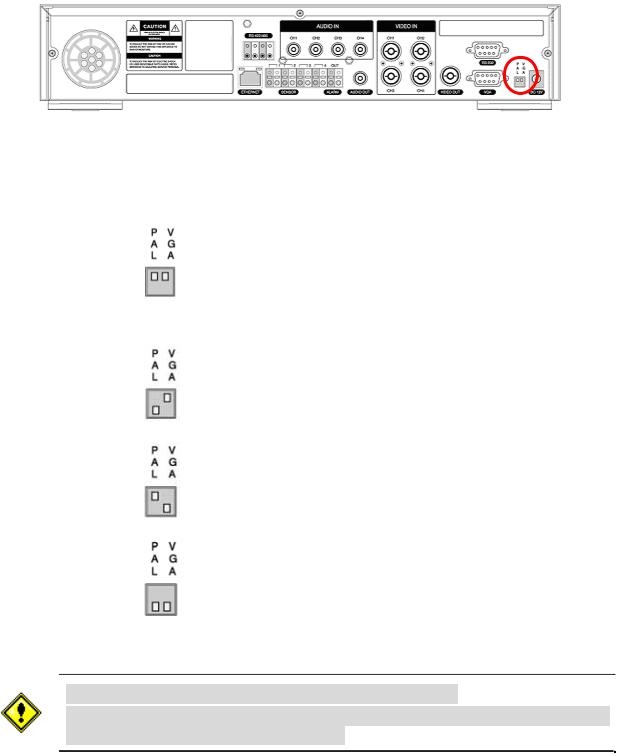
VIDEO SIGNAL SELECT / SETTING
SETTING |
|
Video mode |
|
Video output |
||||
|
|
|
|
|
|
|
|
|
|
NTSC |
|
PAL |
|
BNC |
|
VGA |
|
|
|
|
|
|
||||
|
|
|
|
|
|
|
|
|
|
|
O |
|
X |
|
O |
|
X |
Factory Default |
|
|
|
|
|
|
|
|
|
|
X |
|
O |
|
O |
|
X |
|
|
|
|
|
|
|
|
|
|
|
O |
|
X |
|
X |
|
O |
|
|
|
|
|
|
|
|
|
|
|
X |
|
O |
|
X |
|
O |
|
|
|
|
|
|
|
|
|
Do not change the setting when the power is on.
When the position of the switch is changed, the DVR should be rebooted to apply the new setting.
5
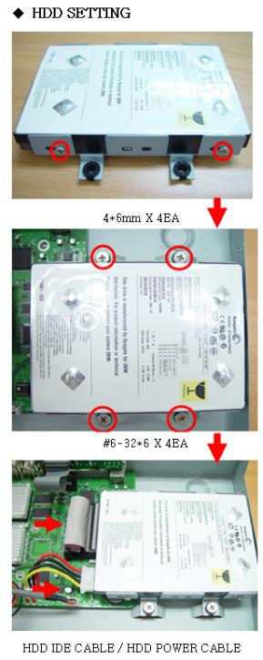
HDD INSTALLATION
Screw the HDD brackets to the HDD and insert rubber rings.
Fix the HDD to the chassis.
Firmly insert IDE cable and power cable to the HDD.
6

SYSTEM SCHEMETIC
Wiring Camera Control port and Sensor input / Alarm output
RS-422/485 |
1 |
2 |
3 |
4 OUT |
|
|
|
|
|
TX+ TXRX+ RX- |
|
|
|
|
|
|
|
|
SENSOR |
|
ALARM |
1 |
2 |
3 |
4 |
Sensor |
|
|
|
|
|
|
|
|
|
|
RS422 |
|
R485 |
|
(-) |
(-) |
1 |
TX+ |
|
DATA+ |
|
|
+12VDC |
2 |
TX- |
|
DATA- |
Dried Contact |
(+) |
(+) |
3 |
RX+ |
|
|
|
|
|
4 |
RX- |
|
|
|
|
|
Adapter
SENSOR INPUT :Connect two signal lines of sensor (infrared rays sensor, heat perception sensor, magnetic sensor) to the desired sensor number.(You can set the type-NC or NOof sensor at “Setup” mode).
ALARM OUTPUT : Use this at 30V/300mA or less operating voltage and current.
When controlling lamp and AC operated equipment, control it using separate outside relay. During normal operation the control output contact is maintained at “Open” status, and during control output the output contact is changed to “Close(short)” status.
SENSOR inputs need dried contact only. Do not input any electric signal.
7
|
TABLE OF CONTENTS |
1. FRONT PANEL ............................................................................................................................................ |
11 |
2. REAR PANEL............................................................................................................................................... |
13 |
3. SETUP.......................................................................................................................................................... |
14 |
3-1. Entering SETUP....................................................................................................................................... |
14 |
3-2. SCREEN.................................................................................................................................................... |
16 |
3-3. RECORD ................................................................................................................................................... |
17 |
3-3-1. Motion Zones...................................................................................................................................... |
18 |
3-3-2. Recording Schedule ........................................................................................................................... |
19 |
3-4. SYSTEM.................................................................................................................................................... |
20 |
3-5. NETWORK ................................................................................................................................................ |
23 |
3-5-1. Port ..................................................................................................................................................... |
23 |
3-5-2. Network types..................................................................................................................................... |
24 |
3-5-3. DDNS.................................................................................................................................................. |
26 |
3-6. Storage ..................................................................................................................................................... |
26 |
3-7. Save Setup ............................................................................................................................................... |
26 |
4. LIVE & SEARCH.......................................................................................................................................... |
27 |
4-1. Live Screen .............................................................................................................................................. |
27 |
4-2. SEARCH ................................................................................................................................................... |
28 |
4-2-1. EVENT Search ................................................................................................................................... |
28 |
4-2-2. TIME LINE Search.............................................................................................................................. |
30 |
4-2-3. PLAY FIRST & PLAY LAST ................................................................................................................ |
31 |
4-2-4. PLAY FIRST ....................................................................................................................................... |
31 |
4-2-5. PLAY LAST......................................................................................................................................... |
31 |
4-2-6. SYSTEM LOG .................................................................................................................................... |
31 |
4-2-7. ARCHIVE Search ............................................................................................................................... |
32 |
8
4-3. PTZF operation ........................................................................................................................................ |
33 |
4-4. Playback mode ........................................................................................................................................ |
34 |
5. ARCHIVING VIDEO INTO USB STORAGE DEVICES ............................................................................... |
35 |
5-1. Capturing images or video ..................................................................................................................... |
35 |
5-2. Transferring still images or videos into USB memory stick or USB CDRW...................................... |
35 |
6. NETWORK CLIENT SOFTWARE................................................................................................................ |
36 |
6-1. Overview................................................................................................................................................... |
37 |
6-2. Minimum PC requirements..................................................................................................................... |
37 |
6-3. Installing the program............................................................................................................................. |
38 |
6-4. Live viewer ............................................................................................................................................... |
38 |
6-4-1. Main user interface ............................................................................................................................. |
38 |
6-4-2. Main control panel .............................................................................................................................. |
39 |
6-5. Search and Playback Viewer.................................................................................................................. |
40 |
6-5-1. Main user interface ............................................................................................................................. |
40 |
6-5-2. Main control panel .............................................................................................................................. |
41 |
6-5-3. Back up............................................................................................................................................... |
42 |
6-6. System configuration.............................................................................................................................. |
43 |
6-6-1. General ............................................................................................................................................... |
43 |
6-6-2. Site...................................................................................................................................................... |
44 |
6-6-3. Event................................................................................................................................................... |
45 |
6-6-4. Record ................................................................................................................................................ |
46 |
6-6-5. Disk..................................................................................................................................................... |
47 |
6-6-6. About................................................................................................................................................... |
47 |
7. FIRMWARE UPGRADE ............................................................................................................................... |
48 |
APPENDIX ....................................................................................................................................................... |
49 |
A-1. DDNS (Dynamic Domain Name Server)................................................................................................ |
49 |
9
A-1-1. |
Creating an ID and password on our free DDNS Service.................................................................. |
49 |
A-1-2. |
Domain Name Registration................................................................................................................ |
50 |
A-1-3. Access to DVR by Domain Name ...................................................................................................... |
52 |
|
A-1-4. Domain Name Management .............................................................................................................. |
53 |
|
A-2. Compatible HDD models........................................................................................................................ |
54 |
|
A-3. Specifications.......................................................................................................................................... |
55 |
|
10
1. Front Panel
The following information will help you operate the front panel controls.
Figure 1.1 Front panel
LED Indication
POWER: LED light is on when power is applied to the system. REC: LED light is on when the system is recording video data. HDD: LED light is on when the system is accessing video data.
EVENT: LED light is on when alarm sensor(s) is/are triggered or motion is detected. NETWORK: LED light is on when client is connected to the system through the network.
Front panel buttons
SEQUENCE: Press to start auto sequencing of the screen in full screen mode. (Toggle) REC: Press to start and stop manual recording.
ARCHIVE: Press to start operations involving archiving in live or playback mode. PTZ: Press to control PTZ operation
SETUP: Press to launch SETUP menu.
SEARCH: Press to go to the search menu. Event search /Time line search /Log /Archive search ESC: Press to return to previous menu screen.
 : Press to move up the menu items in setup mode and to select camera 1 in live mode. It is also
used as the number 1 when entering password.
 : Press to move right in the menu or to change the values in setup mode and to select camera 2 in live mode. It is also used as the number 2 when entering password.
11

 : Press to move down the menu items in setup mode and to select camera 3 in live mode. It is also used as the number 3 when entering password.
 : Press to move left in the menu or to change the values in setup mode and to select camera 4 in live mode. It is also used as the number 4 when entering password.
 : Press to select full screen or quad view in live display mode. It is also used to select desired menu item or to store the setup value in the menu.
 : Press to play or to pause the footage in playback mode.
 : Press to rewind the footage at 1x, 2x, and 4x speed in playback mode.
 : Jump/Step backward. – In playback mode, the playback position moves 60 seconds backward.
 : Jump/Step forward – In playback mode, the playback position moves 60 seconds forward.
 : Press to fast forward the footage at 1x, 2x, and 4x speeds in playback mode.
 : There is a USB port located on the left side of the front panel. This USB port is used to archive footage into a USB memory stick and USB CD-RW.
12
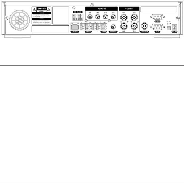
2. Rear Panel
Figure 2.1. Rear Panel
Rear panel connections
VIDEO IN: Four connectors for video input(NTSC/PAL).
VIDEO OUT: Composite video output in NTSC/PAL format
AUDIO IN: Four connectors for audio input(line level).
AUDIO OUT: One connector for audio output(connect a headphone or a speaker).
VGA: Connector for VGA monitor
RS-232: For engineering use only
RS-485/422: For camera control use
SENSOR: Connector for sensor device connection. 4 sensors can be connected to the equipment sensor 1, 2, 3, 4 are dedicated to Video channel 1, 2, 3, 4, respectively. Either normal open (NO) or normal close (NC) sensor can be selected for each sensor. Simple On/Off switching.
ALARM: Connector for alarm device connection. Provides simple On/Off switching using relay. 0.5A/125V, 1A/30V
LAN: RJ45 connector for LAN connection
DC12V: Apply 12V DC using the DC adaptor supplied with the equipment.
SWITCHES: NTSC/PAL, BNC/VGA Select switch
13
3. SETUP
The following sections detail the initial setup of the DVR
3-1. Entering SETUP
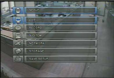
When you press the SETUP button, the DVR will ask for a password. The default password is 1111, which can be entered by pressing the up button ( ) 4 times and then pressing the SEL button. We recommend you protect the system by assigning a new password immediately. The procedure for assigning a password is found in section 3.4. After a password has been assigned, enter the password by using the 4 direction keys (representing 1, 2, 3, & 4), and then press the SEL button for password validation. Once the password is entered, you will see the screen as shown in Figure 3.1.1. Navigate through the menu items and press the SEL button to enter the sub-category menu.
Figure 3.1.1. Setup menu screen
14

SETUP |
LIVE |
OSD |
|
|
|
SEQUENCE |
|
|
|
SEQ-DWEL TIME |
|
|
|
EVENT BEEP |
|
|
|
OSD CONTRAST |
|
|
|
CHANNEL |
DISPLAY, SEQ LIST, |
|
|
|
BRIGHTNESS, CONTRAST, |
|
|
|
HUE, SATURATION |
|
RECORD |
RESOLUTION |
|
|
|
CHANNEL |
FRAME RATE, QUALITY, |
|
|
|
RECORDING, MOTION ZONE, |
|
|
|
MOTION SENSITIVITY, |
|
|
|
SENSOR TYPE, PRE RECORD, |
|
|
|
POST EVENT RECORD, ALARM, |
|
|
|
ALARM DURATION, AUDIO |
|
|
SCHEDULE |
|
|
SYSTEM |
DVR ID |
|
|
|
DESCRIPTION |
|
|
|
LOAD FACTORY DEFAULT |
|
|
|
ADMIN PASSWORD |
|
|
|
NETWORK PASSWORD |
|
|
|
DATE FORMAT |
|
|
|
SET DATE & TIME |
|
|
|
PTZ CONTROL |
|
|
|
LANGUAGE |
|
|
|
REMOTE CONTROLLER ID |
|
|
NETWORK |
PORT |
|
|
|
CLIENT ACCESS |
|
|
|
BANDWIDTH SAVING |
|
|
|
NETWORK TYPE |
|
|
|
DDNS |
|
|
STORAGE |
OVERWRITE |
|
|
|
FORMAT |
|
|
SAVE |
|
|
|
Table 3.1.1. Setup menu configuration |
|
|
15

3-2. LIVE
Set values for live display. Navigate through the menu items by pressing the UP/DOWN buttons. The value of the menu item may be changed by pressing the LEFT/RIGHT buttons.
Menu items in LIVE mode setup
OSD Enable/disable on-screen-display.
SEQUENCE Enable/disable sequential display of video channels in full screen mode SEQ-DWELL TIME Dwell time for each channel display in sequential display mode EVENT BEEP Enable/Disable beep alert sound.
OSD CONTRAST Set the visibility level of the On Screen Display (OSD)
CHANNEL Select the channel for applying the following settings by pressing the LEFT/RIGHT buttons. Change the channel name by pressing the SEL button.
DISPLAY Enable/disable display of the video channel in live display mode
SEQ LIST Enable/disable the specified channel to be included in sequential display mode. BRIGHTNESS Change the brightness value for the specified channel
CONTRAST Change the contrast value for the specified channel HUE Change the hue value for the specified channel
SATURATION Change the saturation value for the specified channel
Figure 3.2.1. LIVE mode setup screen
If the values of BRIGHTNESS, CONTRAST, HUE, & SATURATION is changed, the video will be recorded as same as changed.
16

3-3. RECORD
Set the values for recording video. Navigate through menu items by pressing the UP/DOWN buttons. User can change the value of the menu item by pressing the LEFT/RIGHT buttons.
Menu items in RECORD mode setup
RESOLUTION Set resolution.
CHANNEL Select the channel for applying the following settings. This channel name can be changed on LIVE menu.
FRAME RATE Set the frame rate for the specified channel. The sum of the frame rate values from each channel cannot exceed maximum frame rates for a particular recording resolution. Typical values of the maximum frame rate for NTSC video are 120/100 fps for 360*240(NTSC)/360*288(PAL) and 30/25 fps for 720*480(NTSC)/720*576(PAL).
QUALITY Select the recording quality for the specified channel from normal, high, and super. RECORDING Assign the recording mode for each channel. Recording modes: Continuous, Motion,
Sensor, Schedule, and Disable.
MOTION ZONE Select Full Zone or Partial Zone for motion sensing. If the Partial Zone is selected, screen will be change as shown in figure 3.3.2.
MOTION SENSITIVITY Set the motion sensitivity for the specified channel. Control the motion sensitivity from 1 to 9.
SENSOR TYPE Set the type of sensor for the specified channel from none, N/O (normal open), and N/C (normal closed).
PRE RECORD Enable/disable pre-event recording. Pre-event recording time is 5 sec and only intraframes are recorded for pre-event recording.
POST EVENT RECORD Set post event recording time duration for the specified channel. ALARM Enable/disable alarm generation for the specified channel.
ALARM DURATION Set alarm time duration for the specified channel. AUDIO Enable/disable audio for the specified channel
SCHEDULE Set recording schedule. If this menu item is selected, screen will change as shown in figure 3.3.3.
17
 Loading...