


Premium Entry Level Real-Time DVR
User’s Manual
▪H.264 Stand-Alone DVR
▪Independent Dual Display
▪Triple Streaming
▪Auto IP Detection
▪iPhone, Android Phone Support

Preface
We welcome you as a new user of the world's best digital video recorder (DVR), and the leading Digital Video Surveillance System. For effective usage, please read this manual carefully. For future reference, please keep this manual close to hand.
Copyright/Authentication/Trademark/Limited Warranty
Copyright
This manual is produced under copyright law. None of its contents may be copied or duplicated without prior approval.
Copyright 2009~
Authentication
CE, FCC, KCC
Trademark
Ethernet(TM) is the trademark of Xerox Corporation.
Microsoft(TM), MS-DOS(TM), Windows(TM logo), Windows(TM) and Windows NT(TM) are the trademarks of Microsoft Corporation, used in the United States and elsewhere.
Limited Warranty
•The manufacturer, importer and agent shall not be responsible for accidental damage (including injury) and other damage caused by inappropriate use or operation of this product.
•The information in this manual is prepared based on the current specifications for the product. The manufacturer is currently adding new functions and will continue to upgrade the product with new technology. All specifications may be changed without notice to individual users.
Cautions
We strongly recommend that users read all safety cautions carefully before operating the product, to operate the product appropriately.
Since the indicated cautions contain critical safety information, they must be fully complied with. The cautions are categorized into Danger, Warning, Caution and Important.
Risk of death or serious injury.
This is the highest priority danger warning.
Risk of serious or lesser degree of injury.
May also cause damage to the product or to property.
Risk of minor injury or damage.
Requirements or limitations regarding operation. Users are recommended to read the relevant details carefully so as to operate the product properly and without harm.
The above cautions indicate the degree of damage that may occur due to inappropriate use of the system.
1

Risk of death or serious injury.
This is the highest priority danger warning.
•RISK OF EXPLOSION IF BATTERY IS REPLACED BY INCORRECT TYPE. DISPOSE OF USED BATTERY ACCORDING TO THE INSTRCTIONS.
•THIS EQUIPMENT IS INDOOR USE AND ALL THE COMMUNICATION WIRINGS ARE LIMITED TO INSIDE OF THE BUILDING.
•Please connect the power cord only to the type of AC outlet indicated in the manual or product specification. If connected to other types of power outlet, fire and electric shock may result.
•Do not expose the product to moisture and dampness. Doing so may result in fire and electric shock.
•Do not place heavy objects on top of the power cord. Damage to the power cord may result in fire and electric shock.
•Do not place containers with liquid or small metal objects on top of the product. Liquid or small metal objects getting into the unit may lead to fire and electric shock.
•Do not score, bend, twist, pull or heat the power cord. Damage to the power cord may lead to fire and electric shock.
•Do not remove the top casing of the product. Doing so may result in electric shock. If internal examination and maintenance are deemed necessary, contact the authorized system vendors or installers.
•Do not modify the product in any way. Doing so may lead to fire and electric shock.
•In case of lightning, immediately turn off the power switch and remove the power cord from the power outlet. Failure to do so may result in fire and electric shock.
•Please use only the power cord supplied with the product. Use of other power cords may result in fire and electric shock.
•In case of smoke, smell or noise, immediately turn off the power switch and remove the power cord from the power outlet. Continued operation of the product may result in fire and electric shock. Request a maintenance service from the authorized system vendors or installers.
•If the product is dropped or damaged, turn off the power switch and remove the power cord from the power outlet. Continued operation of the product may result in fire and electric shock. Users should request a maintenance service from the authorized system vendors or installers.
•Do not touch the product with wet hands. Doing so may result in electric shock.
Risk of serious or lesser degree of injury.
May also cause damage to the product or to property.
•Do not leave the power cord or other cables in passageways. Passers-by may trip and fall.
•Avoid contact with water or beverages. Contact with water or beverages may result in damage that cannot be repaired.
•In case of lightning, immediately turn off the power switch and remove the power cord from the power outlet. The product may otherwise be damaged.
•Excessive current from the product and the camera may result in an electric shock. Connect the power cord to an external device only when the products themselves are disconnected from their power supply.
2
Risk of minor injury or damage.
•If a foreign substance is stuck to the product, remove it using a soft cloth or tissue. Do not use chemical agents (thinner, solvent, etc.) to remove the substance.
•Do not operate or store the product in the following places.
-An area that is either too cold or too hot
-An area of high humidity, or in front of an air-conditioner, or in places subject to sudden temperature changes
-An area where there is excessive dust
-Areas where heat from the product cannot be emitted through both of the product's side ventilation openings
•Do not place credit cards/telephone cards/bank account books/tickets and other objects with magnetic properties near the product.
•Static electricity may cause damage to the internal parts of the product. Please remove static electricity from your body before touching the rear panel and internal electronic parts of the product.
•If this product is damaged beyond repair or reaches its maximum service life, dispose of it in compliance with local laws and regulations regarding the disposal of lead and plastic waste.
Requirements or limitations regarding operation. Users are recommended to read the relevant details carefully so as to operate the product properly and without harm.
•The product may not work properly if the power source is unstable or and if electric shock occurs. Make sure the correct rated power is available.
•The product is designed to be proof against electric power failures; however, damage may occur as a result of power failure. Current data may be damaged or data might not be recorded. Make sure to use an Uninterruptible Power Supply (UPS).
•Since the product is designed to record video data on the hard disk, an error in the hard disk or other miscellaneous errors might prevent the product from recording properly. Periodic maintenance is required for proper operation of the product.
•The product is designed for users to configure their own interface. However a user configuration error could lead to operation malfunction. This product should be set up by certified installers only.
•Since the product is connected - and tightly coupled - to exterior accessories (camera, sensor, LAN, Hard Disk, etc.), there is a risk of malfunction from external causes. Ensure periodic maintenance by the certified installers.
•Use the rack mounting handle provided with the product for installation.
•In this product, 1 Kbyte equals 1,024 bytes, 1 Mbyte equals 1,048,576 bytes and 1 Gbyte equals 1,073,700,000 bytes.
3

Contents
Preface ............................................................................................... |
1 |
Contents............................................................................................. |
4 |
Chapter 1. Introduction ..................................................................... |
6 |
1. The System ......................................................................................................... |
6 |
2. General Features ................................................................................................ |
6 |
3. Specification....................................................................................................... |
7 |
Chapter 2. System Installation .......................................................... |
9 |
1. Package Contents............................................................................................... |
9 |
2. Connecting Devices .......................................................................................... |
10 |
2-1. 4 Channel Premium DVR................................................................................... |
10 |
2-2. 8/16 Channel Premium DVR.............................................................................. |
13 |
3. Cautions ........................................................................................................... |
15 |
Chapter 3. Using DVR....................................................................... |
16 |
1. Basic Operation ................................................................................................ |
16 |
1-1. Front Panel & IR Remote Controller ................................................................... |
16 |
1-2. Turning on the System...................................................................................... |
17 |
1-3. Menu Bar......................................................................................................... |
17 |
1-4. Display Icons ................................................................................................... |
18 |
1-5. User or Admin Login......................................................................................... |
18 |
1-6. The Main Menu ................................................................................................ |
19 |
1-7. Contextual Menu .............................................................................................. |
20 |
2. DVR Configuration............................................................................................ |
21 |
2-1. SYSTEM........................................................................................................... |
21 |
2-1-1. MENU > SYSTEM > Information .............................................................. |
21 |
2-1-2. MENU > SYSTEM > Date & Time............................................................. |
22 |
2-1-3. MENU > SYSTEM > User......................................................................... |
23 |
2-1-4. MENU > SYSTEM > Quick Setup.............................................................. |
24 |
2-1-5. MENU > SYSTEM > System Log .............................................................. |
24 |
2-2. DEVICE............................................................................................................ |
25 |
2-2-1. MENU > DEVICE > Camera..................................................................... |
25 |
2-2-2. MENU > DEVICE > Audio........................................................................ |
26 |
2-2-3. MENU > DEVICE > Alarm........................................................................ |
26 |
2-2-4. MENU > DEVICE > Keyboard .................................................................. |
27 |
2-2-5. MENU > DEVICE > RS232 & RS485 ......................................................... |
27 |
2-3. DISPLAY .......................................................................................................... |
28 |
2-3-1. MENU > DISPLAY > Display .................................................................... |
28 |
2-3-2. MENU > DISPLAY > VGA ........................................................................ |
28 |
2-3-3. MENU > DISPLAY > CVBS....................................................................... |
29 |
2-3-4. MENU > DISPLAY > Digital Signage......................................................... |
29 |
2-4. RECORD .......................................................................................................... |
30 |
2-4-1. MENU > RECORD > Storage ................................................................... |
30 |
2-4-2. MENU > RECORD > Record..................................................................... |
31 |
2-4-3. MENU > RECORD > Utilities .................................................................... |
32 |
2-5. NETWORK ....................................................................................................... |
33 |
2-5-1. MENU > NETWORK > Address ................................................................ |
33 |
2-5-2. MENU > NETWORK > DDNS ................................................................... |
33 |
2-5-3. MENU > NETWORK > Notification ........................................................... |
34 |
4 |
|

2-5-4. MENU > NETWORK > Transmission ......................................................... |
34 |
2-6. EVENT ............................................................................................................. |
35 |
2-6-1. MENU > EVENT > Sensor ....................................................................... |
35 |
2-6-2. MENU > EVENT > Motion ....................................................................... |
36 |
2-6-3. MENU > EVENT > Video Loss.................................................................. |
38 |
2-6-4. MENU > EVENT > Text-In ....................................................................... |
39 |
2-6-5. MENU > EVENT > System....................................................................... |
41 |
3. Playback ........................................................................................................... |
42 |
3-1. Go to Time....................................................................................................... |
43 |
3-2. Calendar Search ............................................................................................... |
43 |
3-3. Event Search.................................................................................................... |
43 |
3-4. Text-In Search.................................................................................................. |
44 |
3-5. Backup Data Playback ...................................................................................... |
44 |
3-6. Playback Control .............................................................................................. |
44 |
4. Backup.............................................................................................................. |
45 |
4-1. Backup ............................................................................................................ |
45 |
4-2. Instant Backup................................................................................................. |
46 |
4-3. Clip Maker........................................................................................................ |
46 |
Chapter 4. Remote Software – Web Viewer .................................... |
47 |
1. Login................................................................................................................. |
47 |
2. Live ................................................................................................................... |
48 |
3. Playback ........................................................................................................... |
49 |
3-1. Calendar Search ............................................................................................... |
49 |
3-2. EVENT Search .................................................................................................. |
50 |
APPENDIX A. - DDNS ....................................................................... |
51 |
1. DDNS(Dynamic Domain Name Server)............................................................. |
51 |
1-1. Use DDNS service after signing up for autoipset.com.......................................... |
51 |
1-2.Use DDNS without signing up for autoipset.com.................................................. |
54 |
Appendix B. - How to Make Digital Signage Data............................ |
55 |
1. Install Program and Codec ............................................................................ |
55 |
2. Making Image Sequence ............................................................................... |
55 |
COMPLIANCE NOTICE OF FCC: ............................................................................. |
59 |
WEEE (Waste Electrical & Electronic Equipment)................................................. |
59 |
ROHS Compliance................................................................................................. |
59 |
5

Chapter 1. Introduction
1. The System
This product is targeted at expanding DVR market. As the market is expanding from Professional to Consumer and into wider sectors, both price and feature oriented products are highly demanded in these days across different market sectors. This product is designed to fulfill these various aspects of different market sectors. Highly affordable, reliable and usable DVR series to fulfill basic needs of DVR with the most satisfactions.
2. General Features
•True H.264 Standard Video Compression
•Embedded Linux System to give you the Ultimate Reliability
•Dedicated DB Structure for Stability
•Various Recording Resolution D1/Half D1/CIF
•CMS (Central Monitoring System)
•Easy Setup same like DVR GUI in CMS
•Web Monitoring, Searching and Setup
•Own Media Player for Backup Playback
•Two USB Port for Mouse operation, Multi USB Hub and Backup
•Up to Two SATA HDD and No Limitation of Capacity
•TwoWay Audio
•Multiple DVRs can be operated with One Keyboard Controller
•Text-In & Relay Output Support
•Real Time Recording and Multi Ch. Playback
•Triple Streaming / Digital Zoom
•iPhone, Android Phone Support
•Independent Dual Display
Dual Display allows user to use both VGA and CVBS outputs same time with different display options. Two different and individual display modes can be set on each monitor output. Also Live Monitoring on one monitor and Playback on another Monitor can be displayed and controlled at the same time. This function will provide such high flexibility and efficiency for monitoring options for users.
Note: This manual covers the 4-channel, 8-channel and 16-channel DVRs. The DVRs are identical except for the number of cameras, audio inputs and alarms. The GUI illustrations and descriptions in this manual are based on the 4 channel model.
6

3. Specification
|
Model |
|
|
4 Channel Premium DVR |
|
Video |
In |
|
4 BNC (without Loop-out) |
|
Out |
|
1 VGA, 1 CVBS (Dual Display) |
|
|
|
|
||
|
Audio |
In |
|
4 RCA (Line-In) |
|
Out |
|
1 RCA (Line-Out) |
|
|
|
|
||
|
|
Sensor In |
|
4 TTL (3+Emergency) |
|
Device |
Alarm Out |
|
2 TTL |
|
|
I/O Interface |
|
RS232, RS485, USB x 2 |
|
|
Speed |
|
Real Time |
|
Display |
Resolution |
|
720 x 480 (NTSC), 720 x 576 (PAL) |
|
|
Split Screen |
|
1, 4, PIP, Digital Zoom |
|
|
Compression |
|
H.264 Codec |
|
|
|
|
120fps@CIF(NTSC) |
|
|
|
|
100fps@CIF(PAL) |
|
|
Speed / |
|
120fps@Half D1(NTSC) |
|
Recording |
Resolution |
|
100fps@Half D1(PAL) |
|
|
|
|
60fps@D1(NTSC) |
|
|
|
|
50fps@D1(PAL) |
|
|
Picture Quality |
|
Very High, High, Standard, Low |
|
|
Mode |
|
Time-lapse, Event, Time & Event, Emergency (E.REC) |
|
|
Display |
|
1, 4, Digital Zoom |
|
Playback |
Search Mode |
|
Calendar Search, Event Search, Text-In Search, Go to Time |
|
|
|
Multi Channel Normal & Reverse Play, |
|
|
|
Playback Mode |
|
|
|
|
|
RW & FF ( x2, x4, x8, x16, x32), Frame to Frame, Pause |
|
|
|
|
|
|
|
|
Interface |
|
Ethernet (10/100 Base) |
|
|
Protocol |
|
TCP/IP, HTTP, DHCP, ADSL(PPPoE), RTP/RTSP |
|
Network |
Application |
|
Live, Playback, Setup, Notification (Callback, E-Mail) |
|
|
Web Browse |
|
Internet Explorer 7 or higher |
|
|
Mobile Support |
|
iPhone, Android Phone (Real Streaming) |
|
|
Storage |
|
2 x SATA HDD |
|
|
Backup |
|
External HDD(USB), External USB Memory |
|
|
Control |
|
Front Panel Button, USB Mouse, |
|
|
|
IR Remote Controller, Joystick Controller |
|
|
|
|
|
|
|
|
OSD |
|
Graphic User Interface (Multilingual) |
|
|
Approval |
|
FCC, CE, KCC |
|
|
ROHS |
|
ROHS Compliance |
|
Power Consumption |
|
DC12V, 3.33A (40W) |
|
|
Operating Temperature |
|
5°C ~ 40°C / 41°F~104°F |
|
|
Operating Humidity |
|
0%~80% / non-condensing |
|
|
|
Dimension |
|
340(W)x67(H)x267(D)mm / 13.39(W)x2.64(H)x10.43(D)inch |
|
|
Weight |
|
2Kg / 4.4lbs (without HDD) |
7

|
Model |
|
|
8 Channel Premium DVR |
|
16 Channel Premium DVR |
|
Video |
In |
|
8 BNC (Loop-out option) |
|
16 BNC (Loop-out option) |
|
Out |
|
1 VGA, 1 CVBS (Dual Display) |
|||
|
|
|
||||
|
Audio |
In |
|
8 RCA (Line in) - Option |
||
|
Out |
|
1 RCA (Line Out) |
|||
|
|
|
||||
|
|
Sensor In |
|
4 TTL (3+Emergency) |
||
|
Device |
Alarm Out |
|
|
2 TTL |
|
|
|
I/O Interface |
|
RS232, RS485, USB x 2 |
||
|
|
Speed |
|
Real Time |
||
|
Display |
Resolution |
|
720 x 480 (NTSC), 720 x 576 (PAL) |
||
|
|
|
|
|
1,4,6,8,9,13,16,PIP, |
|
|
|
Split Screen |
|
1,4,6,9,PIP,Digital Zoom |
|
|
|
|
|
|
Digital Zoom |
||
|
|
|
|
|
|
|
|
|
Compression |
|
H.264 Codec |
||
|
|
|
|
240fps@CIF(NTSC) |
|
480fps@CIF(NTSC) |
|
|
|
|
200fps@CIF(PAL) |
|
400fps@CIF(PAL) |
|
|
Speed / |
|
240fps@Half D1(NTSC) |
|
240fps@Half D1(NTSC) |
|
Recording |
Resolution |
|
200fps@Half D1(PAL) |
|
200fps@Half D1(PAL) |
|
|
|
|
120fps@D1(NTSC) |
|
120fps@D1(NTSC) |
|
|
|
|
100fps@D1(PAL) |
|
100fps@D1(PAL) |
|
|
Picture Quality |
|
Very High, High, Standard, Low |
||
|
|
Mode |
|
Time-lapse, Event, Time & Event, Emergency (E.REC) |
||
|
|
Display |
|
1, 4, 6, 9, Digital Zoom |
|
1,4,6,8,9,13,16,Digital Zoom |
|
Playback |
Search Mode |
|
Calendar Search, Event Search, Text-In Search, Go to Time |
||
|
|
|
Multi Channel Normal & Reverse Play, |
|||
|
|
Playback Mode |
|
|||
|
|
|
RW & FF ( x2, x4, x8, x16, x32), Frame to Frame, Pause |
|||
|
|
|
|
|||
|
|
Interface |
|
Ethernet (10/100 Base) |
||
|
|
Protocol |
|
TCP/IP, HTTP, DHCP, ADSL(PPPoE), RTP/RTSP |
||
|
Network |
Application |
|
Live, Playback, Setup, Notification (Callback, E-Mail) |
||
|
|
Web Browse |
|
Internet Explorer 7 or higher |
||
|
|
Mobile Support |
|
iPhone, Android Phone (Real Streaming) |
||
|
|
Storage |
|
2 x SATA HDD |
||
|
|
Backup |
|
External HDD(USB), External USB Memory |
||
|
|
Control |
|
Front Panel Button, USB Mouse, |
||
|
|
|
IR Remote Controller, Joystick Controller |
|||
|
|
|
|
|||
|
|
OSD |
|
Graphic User Interface (Multilingual) |
||
|
|
Approval |
|
FCC, CE, KCC |
||
|
|
ROHS |
|
ROHS Compliance |
||
|
Power Consumption |
|
DC12V, 3.33 (40W) |
|||
|
Operating Temperature |
|
5°C ~ 40°C / 41°F~104°F |
|||
|
Operating Humidity |
|
0%~80% / non-condensing |
|||
|
|
Dimension |
|
340(W)x67(H)x267(D)mm / 13.39(W)x2.64(H)x10.43(D)inch |
||
|
|
Weight |
|
2Kg / 4.4lb (without HDD) |
||
8
Chapter 2. System Installation
1. Package Contents
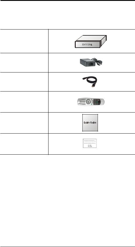
The following components are included in the product:
DVR Unit
DC Adaptor
Power Cord
Remote Controller
Quick Guide
Customer Card
Note: Please download Users’ Guide and Remote Client S/W from the address written on a customer card included in the package.
9
2. Connecting Devices
2-1. 4 Channel Premium DVR
The rear panel of the 4 channel premium DVR comprises the following:
• Front USB: Two USB ports are provided to connect external devices like HDD, Flash memory for Backup, System upgrade or USB mouse on the front panel.
Video Input
Connect the coaxial cables from the cameras to the BNC video connectors.
Audio Input
The DVR can record audio up to 4 sources. Connect the audio sources to the Audio-In RCA connectors. All channels need external pre-amplifiers.
It is the user's responsibility to determine if local laws and regulations permit recording audio.
Audio Out
The DVR does not have amplified audio output, so you will need a speaker with and amplifier.
10

Video Output
Connect the monitors to VGA and CVBS out connector. Dual Display allows user to use both VGA and CVBS outputs same time with different display options. Two different and individual display modes can be set on each monitor output. Also Live Monitoring on one monitor and Playback on another Monitor can be displayed and controlled at the same time. This function will provide such high flexibility and efficiency for monitoring options for users.
Note: VGA Monitor is set as a main monitor when system boots up. To move to another monitor (CVBS) and control it, please use one of following control options.
1.Press and Hold Display button for 3 seconds.
2.Click 2 mouse buttons at the same time.
3.Choose “Move Display Focus” on the contextual menu on GUI.
Please refer to following list for independent dual display/control options.
VGA Monitor |
CVBS Monitor |
|
|
LIVE (O) |
|
LIVE |
PLAYBACK (O) |
|
PTZ (O) |
||
|
||
|
DISIGTAL SIGNAGE (O) |
|
|
LIVE (O) |
|
PLAYBACK |
PLAYBACK (X) |
|
PTZ (O) |
||
|
||
|
DISIGTAL SIGNAGE (X) |
|
|
LIVE (O) |
|
PTZ |
PLAYBACK (O) |
|
PTZ (O) |
||
|
||
|
DISIGTAL SIGNAGE (O) |
|
|
LIVE (O) |
|
DIGITAL SIGNAGE |
PLAYBACK (X) |
|
PTZ (O) |
||
|
||
|
DISIGTAL SIGNAGE (O) |
11
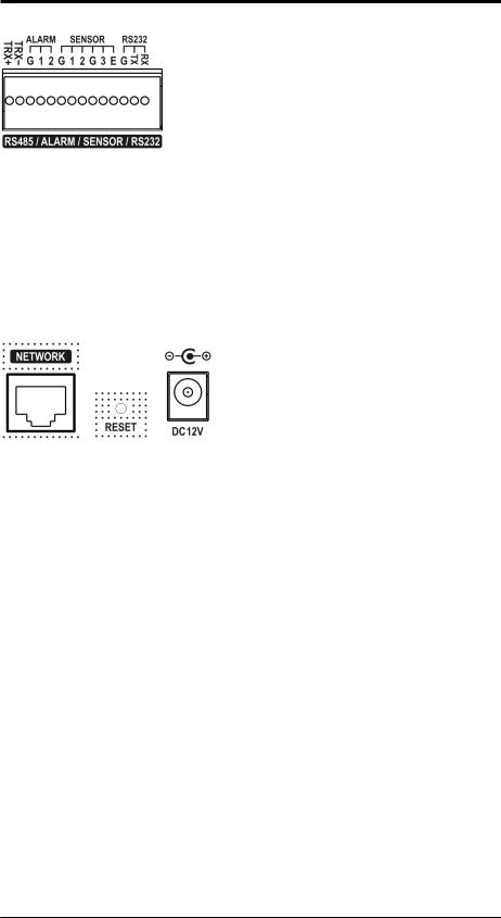
RS485/ALARM/SENSOR
The RS485 connector can be used to control PTZ cameras. The DVR can also be controlled remotely by a control keyboard.
2 alarm output connectors are provided to connect external alarms such as sirens or lights. Alarm output connectors are TTL signals.
3 sensor input and 1 emergency sensor input connectors are provided to connect external devices. You can use sensors to signal the DVR with event. The emergency sensor is designed for Emergency recording only. It will follow Emergency recording setting when it is triggered.
An RS-232C connector is provided to connect an ATM or POS machine for Text-In function.
To make connections on the terminal block, press and hold the button and insert the wire in the hole below the button.
ETC
•Network: Connect a Cat5 cable with an RJ-45 connector to the DVR connector for remote monitoring, remote playback, remote setup. See Chapter 3-2. DVR Configuration for configuring the Network connections.
•Reset: The DVR has a Reset switch that will only be used to return all the settings to the original factory settings. To reset the unit, turn the DVR off first. Turn it on again while poking the straightened paperclip in the reset hole. Hold the switch until the DVR is initializing.
•Power Connector: Connect adapter cable to the power connector on the rear panel. (DC12V, 3.33A) Input AC power to the adapter. (free voltage from 100V to 240V, 50/60Hz)
12

2-2. 8/16 Channel Premium DVR
The rear panels of the 6/18 channel premium DVR comprise the following:
[8 Channel Premium Model]
[16 Channel Premium Model]
•Front USB: Two USB ports are provided to connect external devices like HDD, Flash memory for Backup, System upgrade or USB mouse on the front panel. A USB mouse can be connected only front panel USB port dedicated only for mouse.
Video Input
Connect the coaxial cables from the cameras to the BNC video connectors.
Loop-Through Video
Connect the coaxial cables from the Loop BNC connector to another device. Note: To use Loop option, additional looping cable will be needed. Please contact your supplier.
Audio Input
The DVR can record audio up to 8 sources. Connect the audio sources to the Audio-In Multi-connectors. All channels need external pre-amplifiers. (Option – Audio cable)
It is the user's responsibility to determine if local laws and regulations permit recording audio.
13
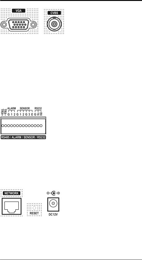
Video Output
Connect the monitors to VGA and CVBS out connector. Dual Display allows user to use both VGA and CVBS outputs same time with different display options. Two different and individual display modes can be set on each monitor output. Also Live Monitoring on one monitor and Playback on another Monitor can be displayed and controlled at the same time. This function will provide such high flexibility and efficiency for monitoring options for users.
Note: VGA Monitor is set as a main monitor when system boots up. To move to another monitor (CVBS) and control it, please use one of following control options.
1.Press and Hold Display button for 3 seconds.
2.Click 2 mouse buttons at the same time.
3.Choose “Move Display Focus” on the contextual menu on GUI.
RS485/ALARM/SENSOR
The RS485 connector can be used to control PTZ cameras. The DVR can also be controlled remotely by a control keyboard.
2 alarm output connectors are provided to connect external alarms such as sirens or lights. Alarm output connectors are TTL signals.
3 sensor input and 1 emergency sensor input connectors are provided to connect external devices. You can use sensors to signal the DVR with event. The emergency sensor is designed for Emergency recording only. It will follow Emergency recording setting when it is triggered.
An RS-232C connector is provided to connect an ATM or POS machine for Text-In function.
To make connections on the terminal block, press and hold the button and insert the wire in the hole below the button.
ETC
•Network: Connect a Cat5 cable with an RJ-45 connector to the DVR connector for remote monitoring, remote playback, remote setup. See Chapter 3-2. DVR Configuration for configuring the Network connections.
•Reset: The DVR has a Reset switch that will only be used to return all the settings to the original factory settings. To reset the unit, turn the DVR off first. Turn it on again while poking the straightened paperclip in the reset hole. Hold the switch until the DVR is initializing.
•Power Connector: Connect adapter cable to the power connector on the rear panel. (DC12V, 3.33A) Input AC power to the adapter. (free voltage from 100V to 240V, 50/60Hz)
14

3. Cautions
•Avoid installing the product where there are direct rays or it is hot by locating near from heat generator. (May cause fire)
•Do not put vase, flowerpot, cup, cosmetics, drug, and anything the contain water on product. (May cause fire or electric shock, and it may injure people by falling)
•Do not insert or drop any metal object (coin, hair pin) or flammable object (match, paper) into air hole. (May cause fire or electric shock)
•Do not put any heavy object on it. (May injure people by being fell or destroyed.)
•Put power plug surely not to be moved. (If not, this may cause fire.)
•Unplug power plug and antenna when there are thunders and lightening. (May cause fire.)
•For cleaning the product, wipe surface with dry towel. Using chemical agent or cleaner may change the color and unpeel paint.
•Do not put several plugs at same time. (May cause electric shock.) If there is smoke or strange smell, stop operation. In this case, turn the power off and unplug it, and then contact our service center. (If you keep using it, this may cause fire or electric shock.)
•Do not unplug by pulling cord. (If cord is damaged, it may cause fire or electric shock.)
•Do not plug or unplug with wet hands. (May cause electric shock.)
•Keep the power cord untwisted. (May cause fire or electric shock.)
•Use proper adapter. (Using too much electric power may cause fire or electric shock.)
•Do not install it at where exposed to rain and wind and water drop. (May cause fire, electric shock and transformation.)
•Keep away from fire. (May cause fire.)
•Do not disassemble or remodel on your own. (May cause malfunction or electric shock.)
•Do not put next to flammable materials like flammable spray. (May cause fire.)
•Do not install it at a place with too much dirt. (May cause fire.)
•Do not install it on unstable places like shaking table and inclined place or shaking place. (May injure users by falling down or being upside down.)
•Do not put an heavy object on power cord or avoid it from being pressed by the device. (May cause fire or electric shock.)
•In case of using extension cord, do not use several devices at same time. (May cause fire with abnormal heating of extension.)
•When there are dirt on power plug pin or power outlet, clean it nicely. (May cause fire.)
•Do not damage on power cord or plug, and bend or twist or pull too much, and put it between other objects or heat. If power outlet insertion part is not tight, do not use it. (May cause fire or electric shock.)
•Do not drop or give a shock to the product. (May injure people or cause malfunction.)
•Do not touch power adaptor or signal controller. (May cause electric shock.)
•Do not put any object too close to block cooling fan. (May cause fire.)
•In case of exchanging batteries with improper type, there might be danger of explosion.
•For used batteries, throw away separately from other garbage.
•When you take out batteries, avoid children from eating them by mistake. Keep them away from children. (If a child ate them, contact a doctor right away.)
15

Chapter 3. Using DVR
1. Basic Operation
1-1. Front Panel & IR Remote Controller
The DVR should be correctly installed before proceeding. The location, shape of the buttons and function keys available may vary depending on the DVR model. Only some of main buttons most commonly used can be found on the front panel.
Control |
Description |
|
USB Port |
Two USB ports are located on the front panel. |
|
|
Pressing camera buttons and Enter button will cause the |
|
Camera Buttons (1~0) |
selected camera to display full screen. Buttons are used to |
|
|
enter passwords. |
|
|
Enters the Setup Menu. User will need to enter the authorized |
|
MENU / EXIT Button |
password to assess Setup. In Playback mode, MENU button |
|
|
displays the Playback Menu. |
|
DISPLAY Button |
Changes the screen display mode in the current screen or |
|
playback screen. |
||
|
||
SEQUENCE Button |
Displays live channels sequentially. |
|
Up, Down, Left, Right |
These are used to change settings for the product in MENU |
|
Arrow, ENTER Buttons |
mode or used in PTZ control mode. (pan, tilt) |
|
BACKUP Button |
Copies recorded data to an external storage device. |
|
PLAYBACK Button |
Changes to the playback mode from the live mode. |
|
|
Under playback mode, the button can be used to pause the |
|
PAUSE Button |
playback screen. |
|
|
- Display menu to save PTZ preset under PTZ mode. |
|
|
Plays the video forward. Press the button repeatedly to |
|
|
increase play speed up to max 32 times (1, 2, 4, 8, 16, 32 |
|
PLAY Button |
times) faster. Use this button to move right when setting the |
|
|
menu. |
|
|
- Focus on far distance under PTZ mode. |
|
|
Plays the video backward. Press the button repeatedly to |
|
|
increase play speed up to max 32 times (1, 2, 4, 8, 16, 32 |
|
R.PLAY Button |
times) faster. Use this button to move right when setting the |
|
|
menu. |
|
|
- Zoom Out under PTZ mode. |
|
|
Move forward by one frame under Pause. Use this button to |
|
STEP FORWARD Button |
move up when setting the menu. |
|
|
- Focus on near distance under PTZ mode. |
|
|
Move backward by one frame under Pause. Use this button to |
|
STEP BACKWARD Button |
move down when setting the menu. |
|
|
- Zoom In under PTZ mode. |
|
16 |
|
PTZ Button |
Changes to the PTZ control mode from the live mode. |
ZOOM Button |
Zooms the current image on the screen. |
PIP Button |
Changes to PIP screen mode from live screen. |
AUDIO Button |
Selects a camera for live & playback audio output. |
OSD Button |
Turns on/off the OSD display. |
LOG Button |
Checks the system’s log information. |
ID Button |
Selects the DVR system ID. (Remote controller only) |
|
Pressing the E.REC button stars Emergency Recording Mode of |
E.REC Button |
all camera channels, and displays "!" on the screen. Pressing |
|
the button again will stop E.REC mode. |
Status LED |
Power, HDD, Network, Alarm |
1-2. Turning on the System
Connecting the power cord will turn on the power of DVR. It will take approximately 10 to 30 seconds for the system to be initialized. Once the system is initialized, it will display live screen, and begin to record video automatically.
Note: To turn off the system, select SHUTDOWN under main menu (MENU > SHUTDOWN) and unplug the power cord when the shutdown message appears.
Note: When installing the HDD for the first time, the HDD should be formatted first. “MENU > RECORD > Storage > HDD format”
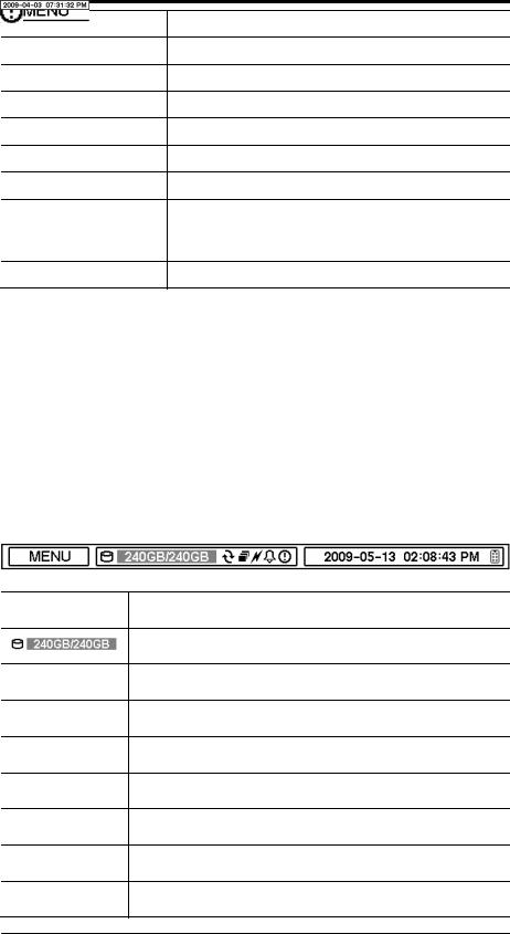
1-3. Menu Bar
The menu bar will appear on the bottom of the screen as shown below.
Pressing the Menu will bring up the main menu list.
Shows the % of HDD being used.
Turns on when the HDD is set to be overwritten.
Sequence display mode.
Turns on when the system is connected to the network.
Turns on when the Alarm is being activated.
E.REC (Emergency Recording) Mode.
Displays date & time.
IR Remote Controller
17
 Loading...