

Page 1
-
8
-
2
MODEL GL-C
INSTALLATION & OPERATION
Rev. 1.00A
CMA DISHMACHINES
12700 KNOTT AVENUE
GARDEN GROVE, CALIFORNIA 92841
800-854-6417
FAX 714
95
www.cmadishmachines.com
141
Page 2

TABLE OF CONTENTS
MODEL GL-C
1. RECEIVING ...................................................................................................2
2. SPECIFICATIONS.........................................................................................3
3. INSTALLATION.............................................................................................4
3.1. ELECTRICAL .................................................................................................................................... 4
3.2. PLUMBING....................................................................................................................................... 4
4. GLC FLOW DIAGRAM..................................................................................4
5. OPERATION..................................................................................................6
5.1. FILLING THE WASH TANK ............................................................................................................... 6
5.2. OPERATING INSTRUCTIONS ............................................................................................................. 6
3.2.1. Proper Chemical Dosage........................................................................................................ 6
5.3. CLEANING INSTRUCTIONS ............................................................................................................... 7
3.3.1. Daily Cleaning Instructions.......................................................................................................... 7
3.3.2. Weekly Cleaning Instructions....................................................................................................... 7
6. MAINTENANCE.............................................................................................8
6.1. TROUBLESHOOTING......................................................................................................................... 8
7. ELECTRICAL DIAGRAM ............................................................................10
Page 3

Receiving
1. Receiving
1. Remove the packing material from the top of the conveyor stack.
2. Remove all packing material and tape securing components within the machine. Check
that both trays are positioned properly.
3. Check for the following component parts:
A. Check that the deflector screen is secure in the rinse drain.
B. Check the position of the GL-C curtain.
C. Chec k that the conveyor is level and the drive gear is engaged in the conveyor’s outer
rim grooves.
D. Check that overflow drain tube is in position in detergent tank.
E. Check that the detergent tank screen in the detergent tank is in position.
F. Check that the drain screen is in position.
4. Important: Read and follow up instructions completely.
MODEL GL-C Installation & Operation Manual Rev. 1.00A –2/23/06 Page 2
Page 4
Specifications
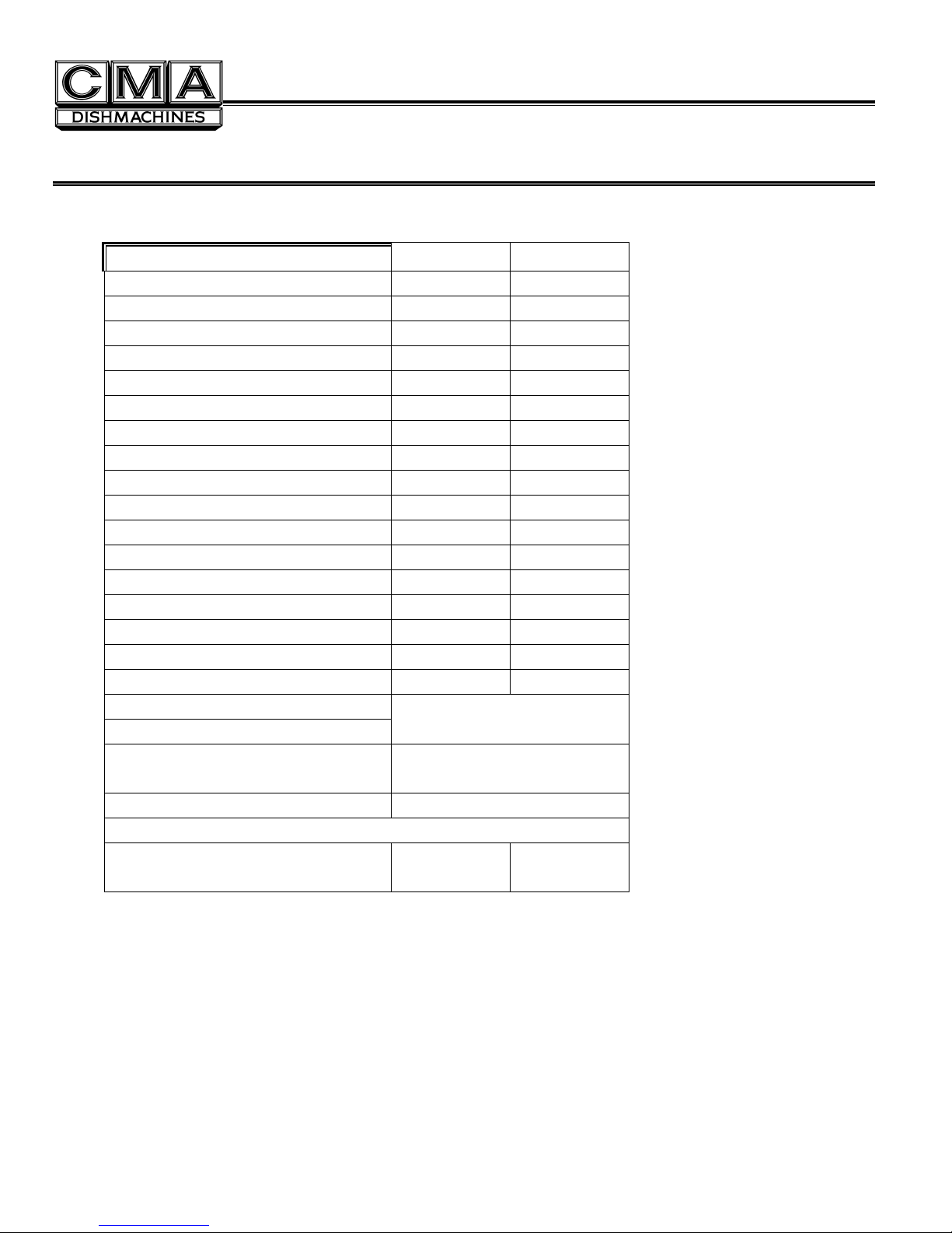
2. Specifications
WATER CONSUMPTION
HOT WATER INITIAL FILL 3 GAL. 11.35 L.
HOT WATER PER HOUR (max) 12 GAL. 45.42 L.
COLD WATER PER HOUR 168 GAL. 636 L.
OPERATING CAPACITY
(2-1/2”) GLASSES PER HOUR 1000 -
WATER REQUIREMENTS
COLD WATER INLET 1/2” HOT WATER INLET 1/2” DRAIN CONNECTION 1-1/2” TEMPERATURES
INLET COLD WATER
INLET HOT WATER (recommended)
FRAME DIMENSIONS
DEPTH 25-1/8” 63.8CM
WIDTH 25-1/4” 64CM
HEIGHT 39”-40” 99.1-101.6CM
MAX CLEARANCE FOR GLASSES 10” 25.4CM
ELECTRICAL
TANK HEATER
(Not Booster Heater)
WASH PUMP MOTOR .1HP
SHIPPING WEIGHT
GL-C (Approximate)
156#
75
°F 24°C
140
°F 60°C
240 VAC
15 AMPS
3KW
71 kg
MODEL GL-C Installation & Operation Manual Rev. 1.00 –2/23/06 Page 3
Page 5

Instructions
3. Installation
3.1. Electrical*
A 15 Amp, 240 Volt, 60 Hz dedicated circuit should be used to supply electrical power to the GL-C machine (see
specification sheet page 2). The power connection with the leads L-1,L-2 and Ground must be such that there is
sufficient length of flexible conduit to permit the machine to be moved for cleaning. This machine operates from 208 to
240 Volts.
3.2. Plumbing*
Hot Water Connection
1. Connect a minimum 1/2” water line to the hot water solenoid valve. Supply temperature must be minimum
140°F/60°C,with flow pressure between 25-95 PSI.
2. Hot water consumption is approximately 12 U.S. gph.
Cold Water Connection
1. Connect a minimum 1/2” water line to the cold water solenoid valve. Flow pressure must be between 25-95
PSI.
2. Open ball valve located between hot and cold solenoid valves until temperature reaches 75°F for areas with
very cold rinse water to heat the rinse water which will prevent glasses from cracking.
3. Cold water consumption is approximately 2.8 U.S. gpm.
Drain Connection
1. Connect a 1-1/2” drain line where indicated.
2. PVC pipe is generally recommended, as copper is prone to attack by the sanitizing chemicals.
*Electrical and plumbing connections must be made by a qualified
person who will comply with all available Federal, State, and Local
Health, Electrical, Plumbing and Safety codes.
MODEL GL-C Installation & Operation Manual Rev. 1.00A –2/23/06 Page 4
Page 6

Flow Diagram
4. GLC Flow Diagram
MODEL GL-C Installation & Operation Manual Rev. 1.00 –2/23/06 Page 5
Page 7

Operation
5. Operation
5.1. Filling the Wash Tank
• Ensure that the overflow drain tube is in place in the detergent tank.
• Flip power on-off/flush switch to the “ON” position. The water will fill until the proper level is
reached then turn the heating element “ON”.
• The water temperature is controlled by a heater and a thermostat .The thermostat should be set
for minimum 140°F/60°C.
5.2. Operating Instructions
• Open the door; flip power on-off/flush switch to the “ON” position. Wash tank will automatically fill.
• Ensure there is product in the detergent, sanitizer and rinse agent containers.
• Detergent is fed from the supply container into the detergent tank in controlled am ounts by the
detergent pump. Use detergent at strength recommended by your chemical supplier.
• Load glasses on the conveyor. Start machine with GL-C rocker switch located on front right side of
unit. Machine now will stop and start with conveyor shut-off rod.
3.2.1. Proper Chemical Dosage
The amount of chemical delivered, whether it is detergent, sanitizer or rinse aid, can be obtained by counting
the revolutions of the injector rotors.
• For detergent, contact your chemical supplier for proper type and deterge nt concentration.
Note: Detergent pump only operates when hot water tank is filling.
• For sanitizer, one revolution in 5 seconds equals approximately 12.5ppm Iodin e or 50ppm
chlorine.
• For rinse agent, one revolution in 8 seconds i s re commended.
To Adjust Detergent Injector:
• When a new detergent container is installed, push the prime button in and hold until the detergent feed tube is
full.
• Install the overflow drain tube and switch power on-off/flush switch to the “ON” position. The detergent feeder
will now feed detergent into the detergent tank with water fill.
• To increase detergent volume, turn the detergent adjustment screw clockwise.
• To decrease the detergent volume, turn the detergent adjustment screw counter-clockwise.
To Adjust Sanitizer Injector:
• When a new sanitizer container is installed, push the prime button in and hold until sanitizer feed tube is full.
• Start the washer with rocker switch located on the front of the machine. Take a sample from the final rinse
spray tube to check sanitizer level.
• To increase the volume of sanitizer, turn the adjustment screw clockwise.
• To decrease the volume of sanitizer, turn the adjustment screw counter-clockwise.
To turn rinse agent injector “OFF” in this case, turn the adjustment screw counter-clockwise until the pump
stops turning.
Note: If a sodium Hypochlorite (Chlorine) based sanitizer at a minimum concentra t ion of 50ppm in the final
rinse is used, use chlorine test papers to verify and monitor the 50ppm chlorine level
MODEL GL-C Installation & Operation Manual Rev. 1.00 –2/23/06 Page 6
Page 8

Operation
To Adjust Rinse Agent Injector:
• When a new rinse agent container is installed, push the prime button in and hold until the rinse
injector feed tube is full.
•
•
•
Start the washer. Take a sample from the final rinse spray tubes.
To increase the volume of rinse agent, turn the adjustment screw clockwise.
To decrease the volume of rinse agent, turn the adjustment screw counter-clockwise.
Note:To meet the requirements of N.S.F. standards, Iodophor in a concentration of 12.5ppm
or chlorine at 50ppm must be used in the final rinse.
5.3. Cleaning Instructions
3.3.1. Daily Cleaning Instructions
Remove optional GL-C drain tray & waste collection, from the front of your glasswasher and clean.
Turn glasswasher off by flipping the power on-off/flush switch to the “OFF” position.
Remove right and left trays and GL-C curtain. Wash them with hot soapy water, rinse t horoughly, a nd
then dry.
Remove the conveyor as follows: Remove conveyor hub, flip conveyor shut-off rod to the side, lift
conveyor from the center and pull out.
Remove lower wash and rinse arms. Clean wash and rinse areas with hot soapy water. Rinse
thoroughly, and then dry.
Note: Do not twist spray arms, pull straight out or they will break.
Replace lower wash and rinse arms (they only fit one way). Replace conveyor as follows: With back
end of conveyor raised, mesh drive gear with side of conveyor, pull conveyor towards you until center
of conveyor drops onto pivot. Replace conveyor hub in center of conveyor, flip shut-off bar back to
normal position. Replace left tray ensuring shut-off arm rests within the retainer, then replace right
tray. Replace curtain.
Remove and clean upper and lower wash tank screens.
Remove overflow drain tube from the detergent tank, wash down the interior of the detergent tank.
Replace overflow drain tube and upper and lower wash tank screens.
Note: Do not leave water in tank overnight!!!
Replace optional GL-C drain tray & waste collection making sure hose is connected.
Ensure there is product in the detergent, sanitizer and rinse agent containers. Close the door.
3.3.2. Weekly Cleaning Instructions
Remove upper and lower wash and rinse arms from the manifold and clean spray tubes with Cleaning
Drill p/n 00899.01, Cleaning Brush p/n 00899.02 provided.
Remove detergent, sanitizer, and rinse agent feed lines from containers and place them in a
container of hot water. Hold prime buttons in until the feed lines have been thoroughly flushed.
Replace the feed lines to their proper container and prime product through lines.
MODEL GL-C Installation & Operation Manual Rev. 1.00A –2/23/06 Page 7
Page 9

Maintenance
6. Maintenance
6.1. Troubleshooting
PROBLEM LIKELY CAUSE SOLUTION
Conveyor doesn’t turn
Excessive overspray from
hood section
Lack of pressure in wash
spray tubes
Lack of pressure in rinse
spray tube
Power off at circuit breaker Reset circuit breaker
Drive motor burn out Replace drive motor
Obstruction in wash or rinse
Micro switch on switch support
bracket faulty or not making
contact
Conveyor not in position
Splash curtain not in position Install or adjust
Washer running without any
glasses on conveyor
Spray tubes fallen off hub
Spray tubes plugged Clea r and clean with reamer,
No water in detergent tank
Obstruction in wash arm
Pump not operating
Pump operating but no pressure
Rinse spray tubes dirty
Shut-off valve on supply line
closed
Low water pressure
Remove obstruction
Replace or adjust
Position properly
Keep conveyor loaded with
glasses
Ensure spray tube is pushed
firmly on to hub connection
scraper, and brush
Ensure water supply is on
Ensure detergent tank stand
pipe is in position
Ensure the tank fill switch is in
On-Fill position and that tank
fills with water
Ensure the float switch is
activated by the float cam
Ensure the tank fill solenoid is
operational
Clear obstruction
Check power supply to
machine
Check pump capacitor
Replace pump if required
Check condition of impeller
and stub shaft
Replace if needed
Clean thoroughly with reamer,
scraper, and brush provided
Open valve
Minimum 25PSI flow pressure
required
MODEL GL-C Installation & Operation Manual Rev. 1.00 –2/23/06 Page 8
Page 10

Maintenance
PROBLEM LIKELY CAUSE SOLUTION
Lack of pressure in rinse
spray tube
Water continues to flow to
detergent tank or spray
tubes with machine off
Water temperature low in
detergent tank
Rinse solenoid valve will not
operate
Check coil
Check and install rebuild kit
Replace if necessary
Rinse solenoid valve strainer
Remove screen and clean
plugged
Solenoid valve not sealing Clean seat
Install diaphragm kit
Replace valve
Thermostat setting low
Thermostat defective
Adjust thermostat
Replace
Water on floor around
machine
Chemical containers filling
with water
Chemicals not feeding
Defective float switch
Heater burnt out
Replace
Check and replace
Ensure water level is above
element
Incoming water temp. low
Hot water supply
min.140°F/60°C
Pump seal leaking Replace
Rinse drain in wash area plugged
Clear obstruction, clean
machine
Wash return screen in detergent
Clean
tank plugged
Drain screen under detergent
Clean
tank plugged
Main drain plugged Clean
Detergent tank covers are not
positioned properly causing
Position all top covers to
completely cover top of tank
condensation
Fill chute has lime build-up De-scale detergent tank
Dirty rinse tubes Clean
Worn flow washer in solenoid
Replace
valve
No product in containers Refill containers
Product gelling or crystallizing in
chemical line
Flush all lines with hot water
and use fresh supply of
chemical
Chemical supply strainer plugged
Speed adjustment set too low
Clean with hot water
Increase by turning clockwise
while machine is running/filling
No power to pump
Pump motor defective
Check LED signal
Replace pump motor
MODEL GL-C Installation & Operation Manual Rev. 1.00 –2/23/06 Page 9
Page 11

Electrical Diagram
7. Electrical Diagram
R
O
R
Y
O
E
T
V
O
N
M
O
C
R
P
O
M
T
U
O
P
M
D
I
E
O
H
V
S
N
L
E
A
A
L
W
V
O
S
R
E
T
A
E
H
D
I
E
E
O
V
S
N
L
N
E
I
A
L
R
V
O
S
I
T
E
D
6
8
4
2
C
O
C
N
N
1
5
3
7
B
6
9
3
C
O
C
N
N
1
7
4
A
2
3
1
6
R
F
O
F
H
Y
C
O
-
E
T
I
T
V
U
W
N
H
S
O
S
C
H
T
C
A
T
I
O
L
W
F
S
V
0
4
2
R
E
M
R
V
O
4
F
2
S
N
A
R
T
D
R
A
O
B
T
I
U
C
R
I
C
N
A
S
D
R
A
O
B
T
I
U
C
R
I
C
E
S
N
I
R
D
R
A
O
B
T
I
U
C
R
I
C
R
H
E
C
K
T
I
C
W
O
S
R
MODEL GL-C Installation & Operation Manual Rev. 1.00A –2/23/06 Page 10
H
S
U
L
F
F
R
F
E
O
/
W
N
O
O
P
I
P
R
E
M
R
D
E
E
N
G
T
E
R
T
E
M
I
R
P
R
S
I
N
A
P
E
M
I
R
R
S
E
N
I
R
 Loading...