

Page 1
www.cmadishmachines.com
Buy Parts
MODEL L-1X & L-1X16
PARTS MANUAL
Rev 1.20 12-10-19
800- 854- 6417
F A X 7 1 4 - 8 9 5 - 2141
C M A D I S H M A C H I N E S
1 2 7 0 0 K N O T T A V E N U E
GARDEN GROVE, CALIFORNIA 92841
Page 2

Buy Parts
TABLE OF CONTENTS
MODEL CMA-L-1X & L-1X16
1. PARTS MANUAL .......................................................................................... 3
1.1. INITIAL PARTS KIT (P/N 4001.00) ................................................................................................... 3
1.2. EXPLODED VIEW DRAWINGS ........................................................................................................... 4
1.2.1. Cabinet Assembly ................................................................................................................... 4
1.2.2. Cabinet Assembly (Effective 06/2007) .................................................................................... 5
1.2.3. L-1X Door Assembly (Old Style) ............................................................................................ 6
1.2.4. L-1X/L-1X16 Door Assembly .................................................................................................. 7
1.2.5. Spray System Assembly ........................................................................................................... 8
1.2.6. NST S/S Pump Assembly (Effective November 2015) ........................................................... 9
1.2.7. S/S Pump Assembly (Effective August 2009) .........................................................................10
1.2.8. Pump Assembly ......................................................................................................................11
1.2.9. Plumbing System Assembly (Effective June 2013) .................................................................12
1.2.10. Plumbing System Assembly ....................................................................................................13
1.2.11. Drain System Assembly..........................................................................................................14
1.2.12. Control Box ...........................................................................................................................15
1.2.13. Control Box (Effective 06/2007) ............................................................................................ 16
1.2.14. Peristalic Pump Assembly .....................................................................................................17
1.2.15. Drain Valve ...........................................................................................................................18
1.2.16. Drain Valve (Effective January 2011) ...................................................................................19
1.2.17. Optional Sani Alarm ..............................................................................................................20
Page 3
Parts Manual
MODEL L-1X & L-1X16 PARTS MANUAL Rev. 1.20 Buy Parts Page
3
1. Parts Manual
1.1. Initial Parts Kit (P/N 4001.00)
P/N
DESCRIPTION
Qty
00200.40
SS Pump w/115v Motor Assy.
1
00206.70
Pump Seal Kit New
1
00208.40
Slip Joint Nut O Ring Gasket Buna
1
00307.10
Spray Arm Assy. L-1C, L-1X, L-1X16 Complete
1
00404.82
Motor Contactor Relay
1
00411.00
Micro Switch
1
00415.00
Peristaltic Pump Assembly, 120V/60Hz
1
00421.40
Start/Fill Rocker Switch Amber
1
00425.21
Chemical Tubing Blue (50 Ft/ Coil)
1
00425.23
Chemical Tubing Red (50 Ft / Coil)
1
00425.24
Chemical Tubing White (50 Ft / Coil).
1
00501.00
Timer Motor, 2-Minute
1
0707.00
1/2 Water Solenoid Repair Kit JE
1
00715.00
1/2 Ball Check Valve
1
00738.10
Solenoid Coil JE 115V (3/4 &1/2)
1
02257.00
Squeeze Tube 8" Norprene
1
02257.22
Squeeze Tube 22" Norprene For L-1X
1
03202.00
Thermometer (Capillary)
1
03415.00
Chemical Tube Bulkhead
1
03415.20
Sani Bulkhead Fitting Assy.
1
03481.00
Drain Rocker Switch (GL-X/L-1X)
1
03485.00
Switch Guard (Undercounter Units)
1
04110.00
SS L-1C, L-1X, L-1X16, GLX Drain Screen
1
04113.00
Drain Valve 115V New Style
1
04517.15
Door Stop (Parallel)
1
15524.00
Power Rocker Switch Red 125V
1
NOTE: CMA recommends that the initial parts kit be kept on hand as a back up supply of critical parts
in the event your machine should require emergency service. All the parts included in this kit
are unique to the L-1X and L-1X16 dishmachine.
Page 4
Parts Manual
MODEL L-1X & L-1X16 PARTS MANUAL Rev. 1.20 Buy Parts Page 4
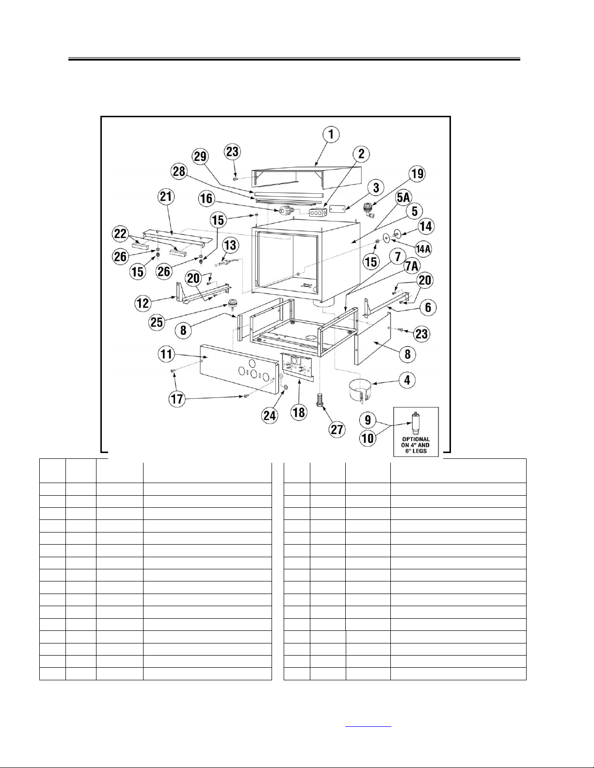
1.2. Exploded View Drawings
1.2.1. Cabinet Assembly
ITEM
NO.
NO.
REQ’D
P/N
DESCRIPTION
ITEM
NO.
NO.
REQ’D
P/N
DESCRIPTION
1 1 04903.73
L-1X Top Cover
14A 1 00752.60
Hole Stopper Gasket
2 1 03420.00
Undercounter Bell Box
15 9 00912.00
Nylon Lock Nut 1/4”-20
3 1 03423.00
Undercounter Bell Box Cover
16 1 00401.10
St-1/2 Straight Connector
4 1 04109.11
^Band Sump Heater 115V
17 2 00941.00
10-32 x 5/8” Pan head Screw
5 1 04901.60
Stainless Steel Body
18 1 04914.78
Peri Pump Mount w/ Prime Switch
5A 1 04901.73
Stainless Steel Body L-1X16
19 2 03415.00
Chemical Tube Bulkhead
6 1 04911.60
Tray Track (RH)
20 4 00914.00
1/4-20 x 3/4" Hex Head Bolt
7 1 04902.80
Stand “Open Style” L-1X, L-1X16
21 1 14558.00
Body Magnet Holder
7A 1 04902.20
Bottom Panel (comes w/L1X16)
22 2 00557.80
Door Magnet
8 2 04902.84
Panels for Open Style Stand
23
10
00940.50
10-32 x 3/8” Truss Head Screw
9 4 01146.50
4” Leg (Optional)
24 2 03816.00
Nylon Retaining Washer
10 4 01146.00
6” Leg (Optional)
25 1 03415.60
Chemical Tube Bulkhead Barbed
11 1 04915.78
Peri Pump Panel w/ Prime Switch
26 2 00924.00
Washer SS 1/4"
12 1 04912.60
Tray Track (LH)
27 4 01310.60
Leg Adjusters
13 1 13463.10
Liquid Level Switch)
28 1 14506.45
Gasket Bracket
14 1 01513.60
Hole Stopper
29 1 14506.50
Door Gasket
Thermometer 03202.00 not shown
Page 5
Parts Manual
MODEL L-1X & L-1X16 PARTS MANUAL Rev. 1.20 Buy Parts Page 5
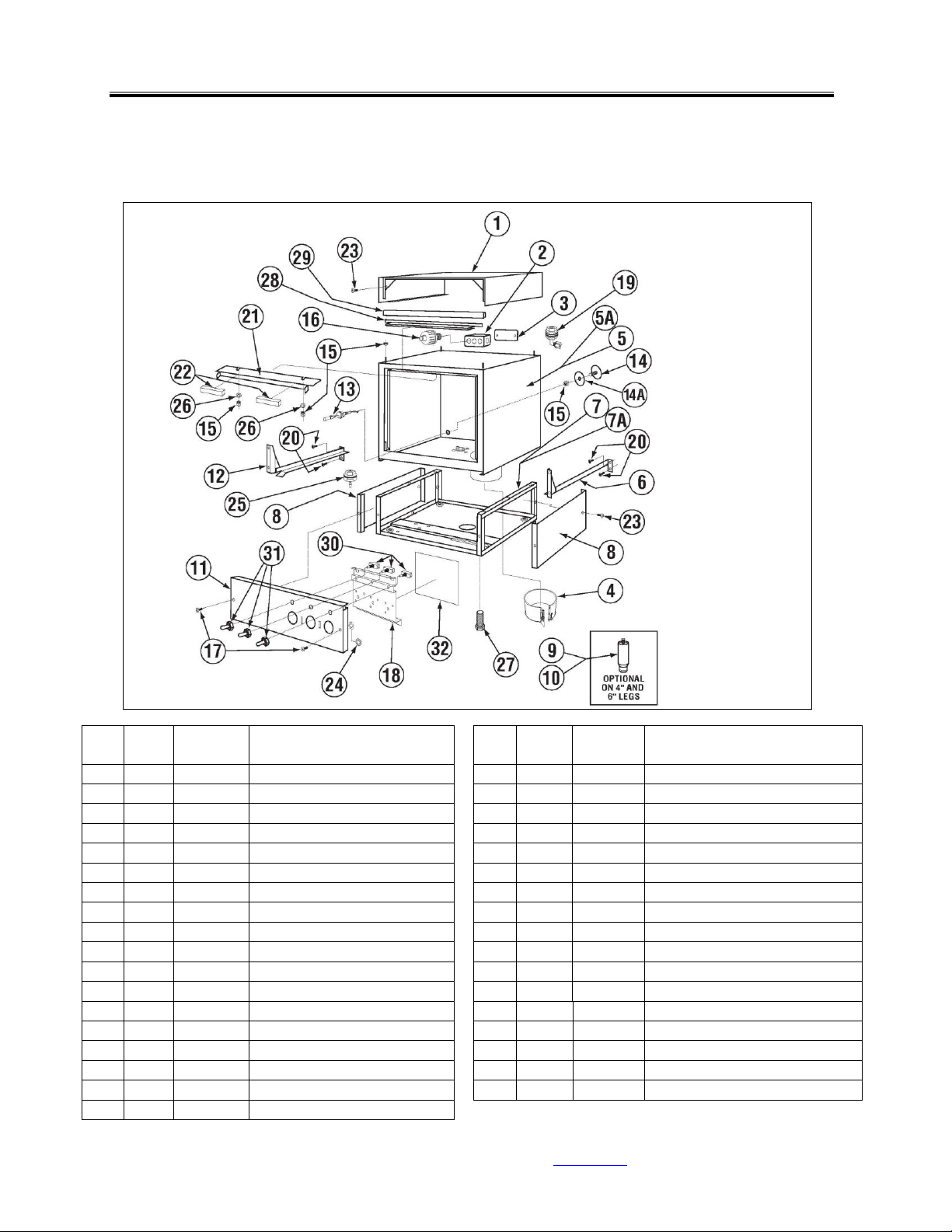
1.2.2. Cabinet Assembly (Effective 06/2007)
ITEM
NO.
NO.
REQ’D
P/N
DESCRIPTION
ITEM
NO.
NO.
REQ’D
P/N
DESCRIPTION
1 1 04903.73
L-1X Top Cover
16 1 00401.10
St-1/2 Straight Connector
2 1 03420.00
Undercounter Bell Box
17 2 00941.00
10-32 x 5/8” Pan head Screw
3 1 03423.00
Undercounter Bell Box Cover
18 1 04914.78
Peri Pump Mount w/ Prime Switch
4 1 04109.11
^Band Sump Heater 115V
19 2 03415.00
Chemical Tube Bulkhead
5 1 04901.60
Stainless Steel Body
20 4 00914.00
1/4-20 x 3/4" Hex Head Bolt
5A 1 04901.73
Stainless Steel Body L-1X16
21 1 14558.00
Body Magnet Holder
6 1 04911.60
Tray Track (RH)
22 2 00557.80
Door Magnet
7 1 04902.80
Stand “Open Style” L-1X,L1X16
23
10
00940.50
10-32 x 3/8” Truss Head Screw
7A 1 04902.20
Bottom Panel (comes w/L1X16)
24 2 03816.00
Nylon Retaining Washer
8 2 04902.84
Panels for Open Style Stand
25 1 03415.60
Chemical Tube Bulkhead Barbed
9 4 01146.50
4” Leg (Optional)
26 2 00924.00
Washer SS 1/4"
10 4 01146.00
6” Leg (Optional)
27 4 01310.60
Leg Adjusters
11 1 04915.78
Peri Pump Panel w/ Prime Switch
28 1 14506.45
Gasket Bracket
12 1 04912.60
Tray Track (LH)
29 1 14506.50
Door Gasket
13 1 13463.10
Liquid Level Switch (Optional)
30 3 03475.00
Prime Switches
14 1 01513.60
Hole Stopper
31 3 03476.00
Prime Switch Boots
14A 1 00752.60
Hole Stopper Gasket
32 1 03705.23
Peri Pump Motor Splash Shield
15 9 00912.00
Nylon Lock Nut 1/4”-20
Page 6
Parts Manual
MODEL L-1X & L-1X16 PARTS MANUAL Rev. 1.20 Buy Parts Page 6
1.2.3. L-1X Door Assembly (Old Style)
ITEM
NO.
NO.
REQ’D
P/N
DESCRIPTION
1 1 04906.90
Inner & Outer Panel Assy.
2 2 00605.30
Door Rod Spacer
3 1 00557.60
Reed Switch Magnet
4 2 13805.00
5/6” 18 Lock Nut
5 2 00926.00
5/15” SS Washer
6 2 04517.15
Door Stop (Silicone) Parallel
7 2 04918.10
Door Support Rod Angled
8 1 04916.00
Door Clevis
9 3 13825.00
#8 32 x 1” Pan Head Screw
10 2 00927.00
#8-32 Lock Nut
11 4 00914.10
Bolt 1/4"-20 x 5/8”
12 1 00558.61
Reed Switch Magnet Bracket
ITEM
NO.
NO.
REQ’D
P/N
DESCRIPTION
13* 1 04509.20
Door Complete
14 2 04517.62
Door Support Rod Block
1 1
04509.10
L1-C Door Complete
15 8 00924.00
Washer 1/4" SS
2 1
04510.00
L-1C Door Catch Plate
16 4 00912.00
Lock Nut Nylon 1/4"-20
3 1
04511.00
L-1C Catch Hemi-Ball SS
*Excludes Item #2, 11, 14, 15 & 16
4 1 04512.00
L-1C Catch Ball Spring
Page 7

Parts Manual
MODEL L-1X & L-1X16 PARTS MANUAL Rev. 1.20 Buy Parts Page
7
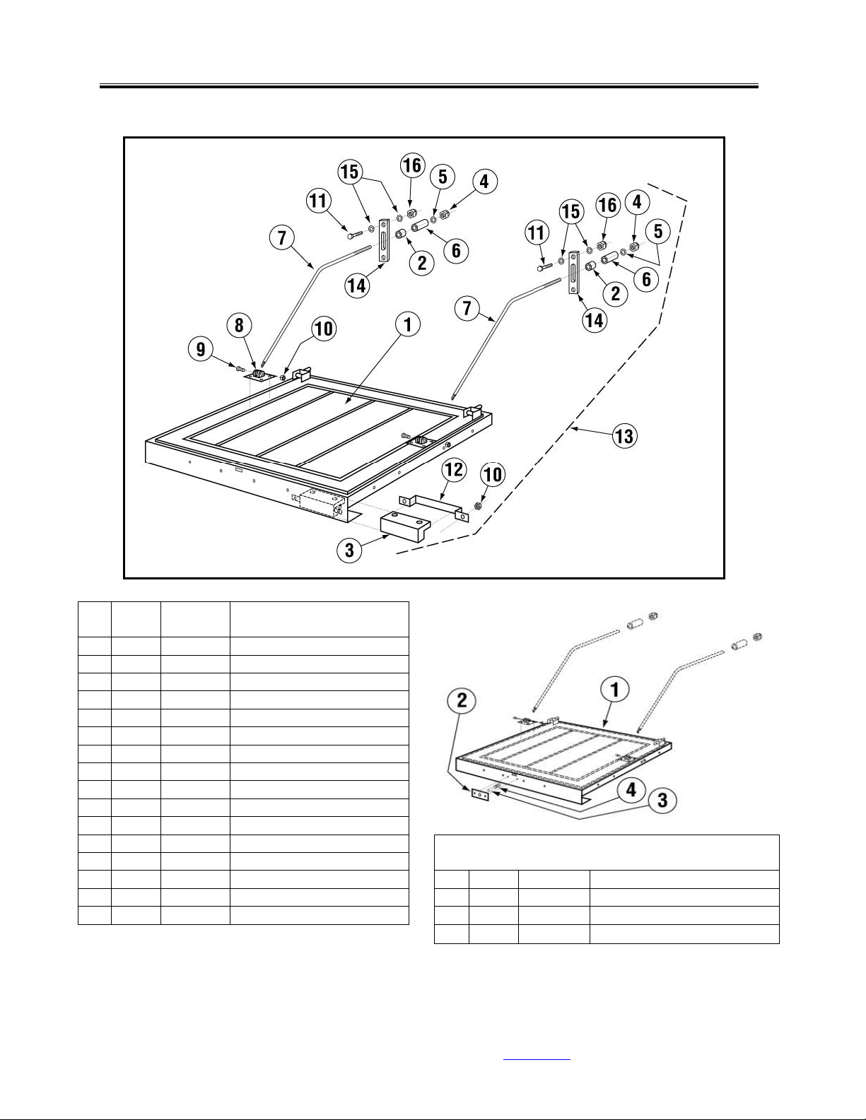
1.2.4. L-1X/L-1X16 Door Assembly
ITEM
NO.
NO.
REQ’D
P/N
DESCRIPTION
ITEM
NO.
NO.
REQ’D
P/N
DESCRIPTION
1 1 04907.90
L-1X Door (New 7-2002)
10 1 14558.61
Door Magnet Holder
1A 1 14506.00
Door for L-1X16
11 2 00965.00
06-32 Lock Nut
2 2 04517.60
Door Support Rod Block
12 2 00605.20
Door Rod Spacer
3 1 14570.00
Door Hinge (RH)
13 2 04517.15
Door Stop (Parallel)
4 1 14570.50
Door Hinge (LR)
14
10
00912.00
1/4"-20 Nylon Lock Nut
5 2 04919.00
Door Rod Screw Pin for Door
15
14
00924.00
1/4" SS Washer
6 1 04918.60
Door Support Rod Right
16 4 00914.10
1/4"-20 x 5/8” Hex Head Bolt
7 1 04919.50
Door Support Rod Left
17 2 14518.00
Splash Guard
8 3 00557.80
Door Magnet
18 4 00924.00
1/4 SS Washer
9 2 00970.60
6 32 x 1/2" Flathead Screw
Page 8

Parts Manual
MODEL L-1X & L-1X16 PARTS MANUAL Rev. 1.20 Buy Parts Page
8
1.2.5. Spray System Assembly
ITEM
NO.
NO.
REQ’D
P/N
DESCRIPTION
1 8 00912.00
1/4"-20 Nylon Lock Nut
2
16
00924.00
1/4" SS Washer
3 8 00929.00
1/4"-20 x 3/4" Truss Head Bolt
4 2 04306.00
Square Manifold Gasket
5 2 04305.10
Silicon Gasket
6 2 04303.00
L-1X Spray Arm Bearing
7 2 00304.04
Spray Arm
8 4 00308.50
Spray Arm End Plug
9 1 04301.00
L-1X Spray Manifold
9A 1 04301.60
L1-X16 Spray Manifold
10 1 00307.10
Spray Arm Assy.
Page 9

Parts Manual
MODEL L-1X & L-1X16 PARTS MANUAL Rev. 1.20 Buy Parts Page 9
1.2.6. NST S/S Pump Assembly (Effective November 2015)
ITEM
NO.
NO.
REQ’D
P/N
DESCRIPTION
ITEM
NO.
NO.
REQ’D
P/N
DESCRIPTION
1 3 00908.00
5/16”-18 x 5/8” SS Hexhead Bolt
12 1 00214.50
1/2" Comp x 3/8” MIP Adapter
2 3 00926.00
5/16” SS Washer
13 1 00208.40
Slip Joint Nut O Ring Buna
3 1 00200.44
NST SS Pump Motor Holder "L"
14 1 00207.00
Slip Joint Nut 1 1/2 x 1 1/4
4 1 00201.65
SS Wash Pump Motor 115v
15 1 00238.00
3/8” Male Plug
5 1 00201.96
Slinger Washer Cone Shape
16* 1 00200.40
NST Assy. Includes 4,5,6,7,8,9, 11
6 1 03224.60
SS Pump Backplate
17 1 03222.74
Flat Washer 8 mm
7 1 03226.70
Volute O-Ring For SS Pump
18 1 03222.72
Shaft Nut Lock Washer 8mm
8 1 00206.70
SS Pump Seal Kit
19 1 13809.70
SS Pump Seal Shaft Nut 8mm
9* 1 03222.61
NST SS Pump Impeller
20 6 00914.70
Socket Head Screw 10 mm
10 1 50302.10
1" MPT x 1" Barb Brass
21 1 00208.21
Slip Joint Nut Friction Ring Plastic
11 1 04206.76
NST SS Pump Cover
* Effective May, 2018 item 9 – 00203.41 NST SS Pump Impeller
and Item 16 – 00200.43 NST Pump Assy. Includes 4-11.
Page 10

Parts Manual
MODEL L-1X & L-1X16 PARTS MANUAL Rev. 1.20 Buy Parts Page 10
1.2.7. S/S Pump Assembly (Effective August 2009)
ITEM
NO.
NO.
REQ’D
P/N
DESCRIPTION
ITEM
NO.
NO.
REQ’D
P/N
DESCRIPTION
1 3 00908.00
5/16”-18 x 5/8” SS Hexhead Bolt
12 1 00214.50
1/2" Comp x 3/8” MIP Adapter
2 3 00926.00
5/16” SS Washer
13 1 00208.40
Slip Joint Nut O Ring Buna
3 1 00200.78
SS Pump Motor Holder "L"
14 1 00207.00
Slip Joint Nut 1 1/2 x 1 1/4
4 1 00201.65
SS Wash Pump Motor 115v
15 1 00238.00
3/8” Male Plug
5 1 00201.96
Slinger Washer Cone Shape
16 1 00200.75
Includes Items 4,5,6,7,8,9,and 11
6 1 03224.60
SS Pump Backplate
17 1 03222.74
Flat Washer 8 mm
7 1 03226.70
Volute O-Ring For SS Pump
18 1 03222.72
Shaft Nut Lock Washer 8mm
8 1 00206.70
SS Pump Seal Kit
19 1 13809.70
SS Pump Seal Shaft Nut 8mm
9 1 03222.60
SS Pump Impeller
20 6 00914.70
Socket Head Screw 10 mm
10 1 50302.10
1" MPT x 1" Barb Brass
21 1 00208.21
Slip Joint Nut Friction Ring Plastic
11 1 04206.75
SS Pump Cover
Page 11

Parts Manual
MODEL L-1X & L-1X16 PARTS MANUAL Rev. 1.20 Buy Parts Page
11
1.2.8. Pump Assembly
ITEM
NO.
NO.
REQ’D
P/N
DESCRIPTION
ITEM
NO.
NO.
REQ’D
P/N
DESCRIPTION
1 7 00908.00
5/16”-18 x 5/8” SS Hexhead Bolt
12 1 04204.00
Compression Nut 2.5”
2 7 00926.00
5/16” SS Washer
13 1 14004.00
1” close Nipple SS
3 4 13805.00
5/16”-18 Nylon Lock Nut
14 1 04601.00
45 Degree Elbow FIP x FIP
4 1 04909.00
Motor Mount
15 1 50302.06
1” MIP x 1” Barb PVC
5 1 00201.00
Water Pump Motor 1 HP
16 1 00200.10
Includes Items 5, 6, 7, 8 and 9
6 8 00921.00
3/8”-16 x 3/4" Hex Bolt
17 1 03226.00
Pump “O” Ring Gasket
7 1 04207.10
Pump Base (Mount)
18 1 00238.00
3/8” Male Plug
8 1 00206.30
Pump Seal Kit New (11/07)
19 1 00214.50
1/2" Comp x 3/8” MIP Adapter
9 1 03222.05
Impeller (universal) open
20 1 00208.21
Slip Joint Nut Friction Ring Plastic
10 1 04207.20
Pump cover
21 1 03232.00
1/8” Male Plug
11 1 00208.40
Slip Joint Nut O Ring Gasket Buna
Page 12

Parts Manual
MODEL L-1X & L-1X16 PARTS MANUAL Rev. 1.20 Buy Parts Page 12
1.2.9. Plumbing System Assembly (Effective June 2013)
ITEM
NO.
NO.
REQ’D
P/N
DESCRIPTION
ITEM
NO.
NO.
REQ’D
P/N
DESCRIPTION
1 1 03623.00
1/2" Vac. Brkr Repair Kit – WATTS
16 1 00915.00
1/4"-20 Hex Nut
2 1 03624.00
1/2" Vacuum Breaker – WATTS
17 1 00924.00
1/4" SS Washer
3 2 00721.00
1/2" Jamb Nut
18 1 00725.50
1/2" Plumbing Strap
4 2 00770.10
5/8 Compression Fitting Nut
19 1 00747.10
Nipple Brass 1/2" x 5”
5 1 00748.00
1/2" Sprinkler Head Assembly
20 1 03602.50
1/2" Y Strainer – Optional
6 1 04605.00
L-1X “U” Tube
21 1 41062.00
1/2 Strainer Ball Valve
6A 1 04605.60
L-1X 16“U” Tube
22 1 00739.50
Vacuum Breaker Cap SS
7 1 00715.00
Ball Check Valve
23 1 03624.25
Vacuum Breaker Bonnet Brass
8 1 00798.00
SS Braided Hose
24 1 00743.12
Tee 1/2C x 1/2C x 1/2 Male
9 1 00214.50
1/2" Comp x 3/8” MIP FTG
25 1 00742.00
Nipple Brass 1/2" x 1-1/2” (Optional)
10 4 00738.10
Water Solenoid Coil J/E
26 1 00744.00
Nipple Brass 1/2" x 2” (Optional)
11 1 00707.00
1/2" Water Solenoid Repair Kit J/E
27 1 03603.20
1/2" Water Solenoid Bonnet
12 1 03603.10
1/2" Water Solenoid Valve J/E
28 1 00786.00
Water Solenoid Valve Plunger
13 1 00745.00
1/2" 90 Degree Street Elbow
29 1 41062.10
^ 1/2 Ball Valve Strainer Only
14 6 00760.00
5/8” Comp. X 1/2" MIP Adapter
30 2 00970.40
6-32 x 1/4" Phillips Pan Head Screw
15 1 04606.00
L-1X “L” Tube
31 1 00706.10
Plunger Spring Only
15A 1 04606.60
L-1X16 “L” Tube
32 2 00770.20
5/8 Compression Fitting Ring
Page 13

Parts Manual
MODEL L-1X & L-1X16 PARTS MANUAL Rev. 1.20 Buy Parts Page 13
1.2.10. Plumbing System Assembly
ITEM
NO.
NO.
REQ’D
P/N
DESCRIPTION
ITEM
NO.
NO.
REQ’D
P/N
DESCRIPTION
1 1 03623.00
1/2" Vac. Brkr Repair Kit – WATTS
17 1 00924.00
1/4" SS Washer
2 1 03624.00
1/2" Vacuum Breaker – WATTS
18 1 00725.50
1/2" Plumbing Strap
3 2 00721.00
1/2" Jamb Nut
19 1 00747.10
Nipple Brass 1/2" x 5”
4 1 03614.00
1/2" Brass (Close) Nipple
20 1 03602.50
1/2" Y Strainer – Optional
5 1 00748.00
1/2" Sprinkler Head Assembly
21 1 41062.00
1/2 Strainer Ball Valve
6 1 04605.00
L-1X “U” Tube
22 1 00739.50
Vacuum Breaker Cap SS
6A 1 04605.60
L-1X 16“U” Tube
23 1 03624.25
Vacuum Breaker Bonnet Brass
7 1 00715.00
Ball Check Valve
24 1 00743.11
^1/2 Tee FxFxF SS
8 1 00798.00
SS Braided Hose
25 1 00742.00
Nipple Brass 1/2" x 1-1/2” (Optional)
9 1 00214.50
1/2" Comp x 3/8” MIP FTG
26 1 00744.00
Nipple Brass 1/2" x 2” (Optional)
10 4 00738.10
Water Solenoid Coil J/E
27 1 03603.20
1/2" Water Solenoid Bonnet
11 1 00707.00
1/2" Water Solenoid Repair Kit J/E
28 1 00786.00
Water Solenoid Valve Plunger
12 1 03603.10
1/2" Water Solenoid Valve J/E
29 1 00706.10
Plunger Spring Only
13 1 00745.00
1/2" 90 Degree Street Elbow
30 2 00970.40
6-32 x 1/4" Phillips Pan Head Screw
14 6 00760.00
5/8” Comp. X 1/2" MIP Adapter
31 1 03604.00
SS Water Solenoid Valve 1/2"
15 1 04606.00
L-1X “L” Tube
32 1 41015.60
1/4 Water Solenoid Coil Only 110V
15A 1 04606.60
L-1X16 “L” Tube
33 1 03604.30
Dema Valve Repair Kit 1/2"
16 1 00915.00
1/4"-20 Hex Nut
34 1 41062.10
^ 1/2 Ball Valve Strainer Only
Page 14

Parts Manual
MODEL L-1X & L-1X16 PARTS MANUAL Rev. 1.20 Buy Parts Page
14
1.2.11. Drain System Assembly
ITEM
NO.
NO.
REQ’D
P/N
DESCRIPTION
1 2 04105.00
Pump Hose 6.5”
2 8 03101.00
1” Hose Clamp #16
3
1
04103.00
Drain Valve 115V
04113.00
Drain Valve 115V New Style
4 1 03108.51
1” Goose Neck Drain Hose
5 1 03109.00
Drain Hose 90DEG 1"
6 1 04110.00
L-1X Drain Screen SS
7 1 50302.06
1” MIP x 1” Barb PVC
Page 15

Parts Manual
MODEL L-1X & L-1X16 PARTS MANUAL Rev. 1.20 Buy Parts Page 15
1.2.12. Control Box
ITEM
NO.
NO.
REQ’D
P/N
DESCRIPTION
ITEM
NO.
NO.
REQ’D
P/N
DESCRIPTION
1 1 04904.60
Top Drawer
10 1 00476.00
Running Light 120V, Green
2 1 00408.80
Timer 2 Minute 8 Cam
11 1 03470.01
Toggle Switch, mom., (.25 flat term.)
2A 8 00411.00
Micro switch
12 1 00406.00
Control box Light Red
2B 1 00501.00
Timer Motor
13 1 00556.10
Reed Switch - ISI
3 1 03408.50
Counter (Panel Mount – Small)
14
1 or 2*
00631.00
Ice Cube Relay
4 1 04415.00
Wire Harness (L-1X)
15 2 00917.00
8-32 PM Nut
5 1 00404.82
Contactor Relay
16 4 00911.00
8-32 x 1/2" Pan Head Screw
6 1 00433.10
Master Switch
17 4 00470.10
Rubber Boot
7 1 00475.30
Toggle Switch DPDT 16A, 2 pos
18
18A 1 1
06231.00
L-1X Drawer Label
8 2 03470.00
Toggle Switch (Momentary)
06231.02
L-1X16 Drawer Label
9 1 03406.64
Drain Toggle Switch DPST
19 2 00940.50
10-32 x 3/8” Truss Head Screw
*Second relay present only with heater option.
Page 16

Parts Manual
MODEL L-1X & L-1X16 PARTS MANUAL Rev. 1.20 Buy Parts Page
16
1.2.13. Control Box (Effective 06/2007)
ITEM
NO.
NO.
REQ’D
P/N
DESCRIPTION
ITEM
NO.
NO.
REQ’D
P/N
DESCRIPTION
1
1
04904.60
L-1X Top Drawer (New 5-02)
15
14
00907.00
6-32 X 1/2 SS Panhead Screw
04904.78
L1X16 Top Drawer Slanted New
16 1 03202.66
Thermocouple
2 8 00411.00
Micro switch
17 1 06232.04
L-1X Drawer Label
3 1 00408.80
Timer 2 Minute 8 Cam
18 1 06232.05
L-1X16 Drawer Label
3A 1 00501.00
Timer Motor
19 1 03203.55
Thermometer Bracket
4
18
00965.00
6-32 Nylon Insert Lock Nut
20 1 03203.51
Single Temp. Display Unit
5
1 (2*)
00631.00
Ice Cube Relay
21 1 00556.10
Reed Switch - ISI
6 4 00470.10
Rubber Boot
22 1 15524.00
Power Rocker Switch (421.10 Cover)
7 1 15520.00
Power Block 12 Position
23 1 03481.00
Drain Rocker Switch (3481.01 Cover)
8 2 13826.10
4-40 X 3/4" Pan Head screw
24 1 00421.40
Start/Fill Rocker Switch (421.41 Cover)
9 1 00404.82
Contactor Relay
25 2 03705.82
Sponge Strip
10 1 00474.00
Delimer Switch Bracket
26 2 00907.10
6-32 X 1/2 Black Oxide Screw-Philp
11
1
00475.30
Delimer Switch DPST 20 Amp.
27 1 03408.50
Counter (Panel Mount – Small)
00475.70
Delimer Sw. 20A 3Pos (New 5-19)
28 2 00916.00
6-32 PM Nut
12 1 03202.60
Thermometer Transformer
29 4 00421.51
6-32 X 1/4 SS Panhead Screw
13 1 00438.00
Snap bushing, Universal
30 1 03485.00
Switch Guard
14 2 13826.50
4-40 Hex Nuts
31 1 04416.01
L-1X/L-1X16 Wire Harness Assy
Page 17

Parts Manual
MODEL L-1X & L-1X16 PARTS MANUAL Rev. 1.20 Buy Parts Page
17
1.2.14. Peristalic Pump Assembly
ITEM
NO.
NO.
REQ’D
P/N
DESCRIPTION
ITEM
NO.
NO.
REQ’D
P/N
DESCRIPTION
1 3 00416.00
Peristaltic Pump Motor
10 6 00448.00
Barrel Connector (Male)
2 3 00417.10
Peristaltic Pump Block (Black)
11
AR
00425.51
Chemical Tubing (Blue)
3 6 00919.00
10-32 x 1 1/2" Pan Head Screw
12
AR
00425.53
Chemical Tubing (Red)
4 3 00918.00
10-32 x 1 1/2" Fillister HD Screw
13
AR
00425.54
Chemical Tubing (White)
5 6 00932.00
Wire Tie – Large
14 2 03415.00
Chemical Tube Bulkhead
6 7 00418.00
Peristaltic Pump Block Cover
15 2 00443.00
Tube Stiffener
7
12
00911.00
8-32 x 1/2" Pan Head Screw
16* 1 00415.00
Complete Peristaltic Pump
8 3 02257.00
Squeeze Tube 8" Norprene
17 1 03415.60
Bulk Head For Sanitizer
9 3 00419.00
Peristaltic Rotor Assembly
18 1 02257.22
Squeeze Tube 22" Norprene For L-1X
19 1 00422.50
Rotor Spacer
*Item 16 includes items 1-4, 6-10.
Page 18

Parts Manual
MODEL L-1X & L-1X16 PARTS MANUAL Rev. 1.20 Buy Parts Page
18
1.2.15. Drain Valve
ITEM
NO.
NO.
REQ’D
P/N
DESCRIPTION
1 1 04103.21
Drain Motor 115V, 60Hz
2 1 04103.14
Drain Valve Spring
3 1 04103.20
Drain Valve Drive Pin
4 1 04103.19
Drain Valve Washer (Thin)
5 1 04103.17
Drain Seal Washer (Black)
5A 1 04103.23
Drain Seal Washer (White)
6 1 04103.12
Drain Valve Housing
7 4 00941.00
#10-32 x 5/8” Pan Head Screw
8 3 04103.24
Drain Valve Housing Spacer
9 1 04103.16
Hinge/Seal
10 1 04103.15
Drain Housing Gasket
11 1 04103.13
Drain Valve Housing Cover
12 4 04103.18
#8 x 5/8” Self-Threading Screw
Page 19

Parts Manual
MODEL L-1X & L-1X16 PARTS MANUAL Rev. 1.20 Buy Parts Page 19
1.2.16. Drain Valve (Effective January 2011)
ITEM
NO.
NO.
REQ’D
P/N
DESCRIPTION
1 1 00104.50
Drain Motor 120V
2 1 04103.14
Drain Valve Spring
3 1 04103.20
Drain Valve Drive Pin
4 1 04103.19
Drain Valve Washer (Thin) SS
5 1 04103.17
Drain Valve Seal Washer (Rubber)
5A 1 04103.23
Drain Seal Bearing (White Washer)
6 1 04113.33
Drain Valve Housing Cover
7 4 04113.18
Valve Cover Screw
8 1 04113.16
Drain Valve Hinge/Seal
9 1 04103.15
Drain Valve Housing Gasket
10 1 04113.12
Drain Valve Housing ( Includes #11&12)
11 2 04113.21
Screw #6-32 X 0.625 Flanged Hex
12 2 04113.23
Screw - #6-32 X 1.5"" Flanged Hex
13 1 04113.13
Valve Cover Assy. Rectangular
Page 20

Parts Manual
MODEL L-1X & L-1X16 PARTS MANUAL Rev. 1.20 Buy Parts Page
20
1.2.17. Optional Sani Alarm
Part Number 12508.00
Exploded View
ITEM
NO.
NO.
REQ’D
P/N
DESCRIPTION
ITEM
NO.
NO.
REQ’D
P/N
DESCRIPTION
1 3 00400.00
Conduit, 3/8” Sealtite
8 5 00931.00
Wire Tie, Small
2 1 00401.00
S.T. 3/8” Straight Connector
9 1 12510.00
Sanitizer Alarm Box Assembly
3 1 00402.00
S.T. 90 Degree 3/8” Connector
10 1 12511.00
Sanitizer Low Level Vacuum Switch
4 1 00406.00
Control Box Light, .5” Diameter, Red
11 1 12512.00
Sanitizer Alarm Buzzer, 120 Volts
5 1 00435.00
Squeeze Tube, 8”
12 4 40126.10
#10 x 3/4" Sheet metal Screw
6 1 00521.00
Wire, 18 Gauge, Orange, 6 ft.
13 4 40127.00
Wall Anchors
7 1 00531.00
Wire, 18 Gauge, White, 6 ft.
14 1 00426.00
Y Hose Connector, 3/16”
 Loading...