

Page 1

-
8
-
2
Owner’s Manual
Keep with machine for reference
MODEL GW-100
PARTS MANUAL
REV.1.00
CMA DISHMACHINES
12700 KNOTT AVENUE
GARDEN GROVE, CALIFORNIA 92841
800-854-6417
FAX 714
MODEL GW-100 Parts MANUAL Rev Rev.1.00 01/17/08 Page1
95
141
Page 2

TABLE OF CONTENTS
MODEL GW-100
1. PARTS MANUAL.......................................................................................... 3
1.1. INITIAL PARTS KIT P/N 1100.47.............................................................................................................. 3
1.2. EXPLODED VIEW DRAWINGS.................................................................................................................. 4
6.2.1. Main Assembly..................................................................................................................................... 4
6.2.2. Conveyor Wheel / Curtain................................................................................................................... 5
6.2.3. Conveyor Shut-Off Rod Assembly........................................................................................................ 6
6.2.4. Control Box Assembly.......................................................................................................................... 7
6.2.5. Soap Tank Assembly............................................................................................................................ 8
6.2.6. Water Inlet Plumbing........................................................................................................................... 9
6.2.7. Sanitizer Plumbing Component Hardware........................................................................................ 10
6.2.8. Vacuum Breaker and Hardware........................................................................................................ 11
6.2.9. GW-100 Wash Pump Assembly.......................................................................................................... 12
6.2.10 Conveyor Drive Assembly................................................................................................................. 13
6.2.11 GW-100 Waste Collector Assy.......................................................................................................... 14
MODEL GW-100 Parts MANUAL Rev Rev.1.00 01/17/08 Page2
Page 3
Parts Manual
1. Parts Manual
1.1. Initial Parts Kit p/n 1100.47
P/N DESCRIPTION Qty
*00120.00 Thermometer (Bi Metal) 1
00201.49 Wash Pump 1
00308.47 Spray Arm End Plug 3
00421.47 Conveyor Rocker Switch 1
00472.47 GL-C Conveyor Shut Off Switch 1
*00631.00 Ice Cube Relay 120V, 12A 1
00631.49 Ice Cube Relay 120V, 20A 1
00715.47 3/8” Check Valve 1
00810.49 GL-C Drive Motor 120V 1
00811.47 Drive Motor Spring 1
00815.00 GL-C Peri Pump Complete 1
00820.00 GL-C Peri Pump Circuit Board 1
00821.00 GL-C Transformer 1
00839.00 Squeeze Tube w/conn. 3
00899.01 Cleaning Drill
00899.02 Cleaning Brush
03470.47 Power on-off/ Flush Switch 1
*03475.00 Primer Switch - Push Button 1
*03623.00 1/2 Vac Breaker Repair Kit Watts 1
15417.10 1250 Watt Heater
*13417.89 Heater Thermostat (EGO) 1
13418.49 GL-C Auto-Fill Timer 1
*13605.00 Pressure Gauge 1
13703.47 GL-C Curtain – Full Size 1
13703.57 GL-C Curtain – Half Size 1
41015.49 Solenoid Valve 3/8" 120V 1
1
1
1
NOTE: Important! CMA recommends that the initial parts kit be purchased immediately and kept on
hand as a back up supply of critical parts in the event your machine should require
emergency service.
All the parts included in this kit are unique to the GW-100 glasswasher (except those with *).
MODEL GW-100 Parts MANUAL Rev Rev.1.00 01/17/08 Page3
Page 4
Parts Manual
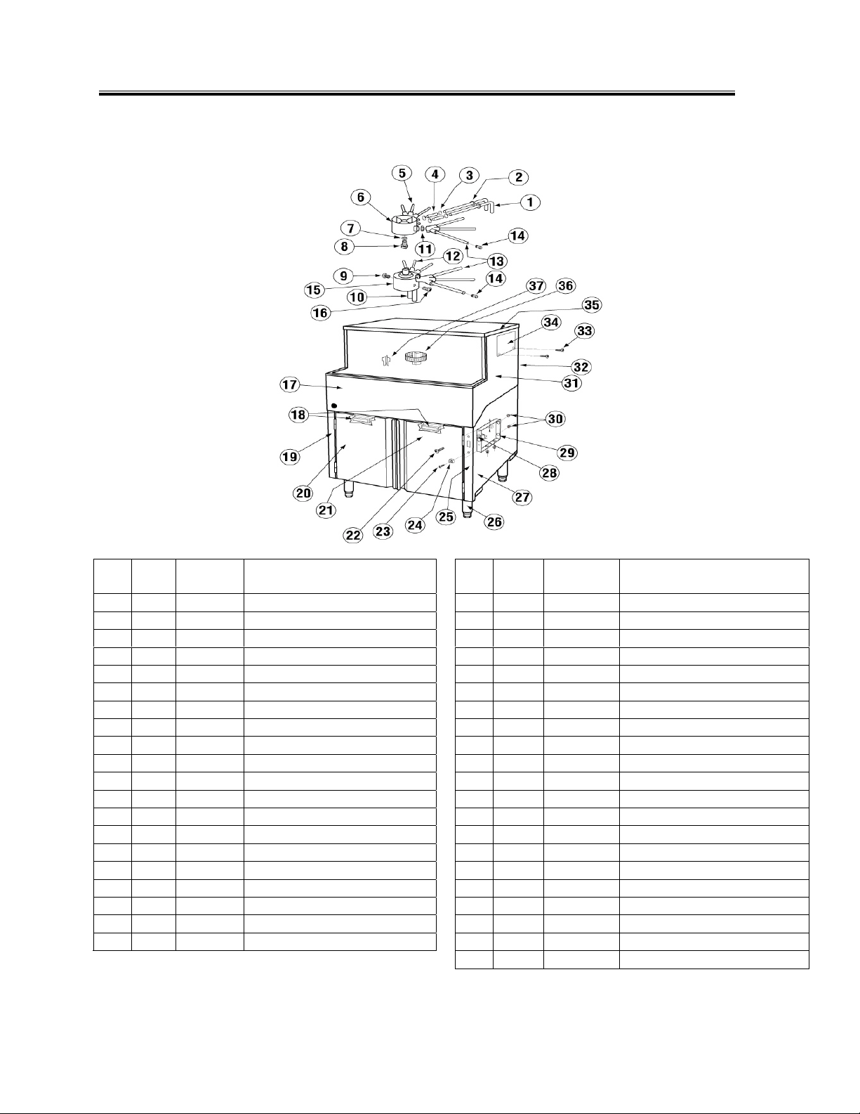
1.2. Exploded View Drawings
6.2.1. Main Assembly
ITEM
NO.
NO.
REQ’D
1 2 05004.00 Upper Spray Base Inlet Tube 21 1 16306.50 GW-100 Right Door
2 2 14754.10 Grommet 22 2 00940.50 Screw, 10-32 x 3/8”
3 4 03101.47 Clamp #6 23 1 00941.00 10-32 X 5/8 Panhead Screw
4 1 03106.47 Braided Hose 3/8” 24 1 00421.45 GL-C Switch Bumper
5 2 14755.00 Wash Arm 25 1 16402.60 Front Pillar (Right Hand) 2” taller
6 1 14752.00 Upper Spray Base 26 4 01146.00 Leg 6-1/2”- Thread
7 1 00924.00 Washer,1/4” 27 1 16331.00 GW-100 Base
8 1 00910.00 Bolt, 1/4-20 x 1 1/2" 28 1 00421.47 Conveyor Rocker Switch
9 4 00940.60 Screw, 10-32 x 3/8” 29 1 16514.50 Conveyor Switch Box
10 1 14756.00 Lower Spray Base Inlet Tube 30 4 00438.00 Snap Bushing Universal 875-11
11 4 14752.10 Spray Base “O” Ring
12 2 14755.00 Wash Arm 32 1 16330.00 GW-100 Wash Tank
13 2 14754.00 Rinse Arm 33 4 00940.60 Screw, 10-32 x 3/8”
14 6 00308.47 Spray Arm End Plug 34 1 16510.50 Vacuum Breaker Access Cover
15 1 14753.00 Lower Spray Base 35 1 16513.00 Top Panel
16 2 00940.50 Screw, 10-32 x 3/8”
17 1 16302.50 GW-100 Face Trim 37 1 16571.00 Drain Deflector (Wash)
18 2 00812.47 Magnetic Door Catch 38 1 16530.50 Tank Support Bracket *
19 1 16302.65 GW-100 Front Pillar (Left Hand) 39 1 00860.01 GL-C Moisture Pad 10 x 23 *
20 1 16306.00 GW-100 Left Door 40 1 00860.02 GL-C Moisture Pad 3 x 23 *
*Not shown. 41 1 00860.03 GL-C Moisture Pad 10 x 12 *
P/N DESCRIPTION
ITEM
NO.
NO.
REQ’D
31 1 16302.00 GW-100 Side Panel Wrap
36 1 16571.20 Deflector Screen (Rinse)
P/N DESCRIPTION
MODEL GW-100 Parts MANUAL Rev Rev.1.00 01/17/08 Page4
Page 5
Parts Manual
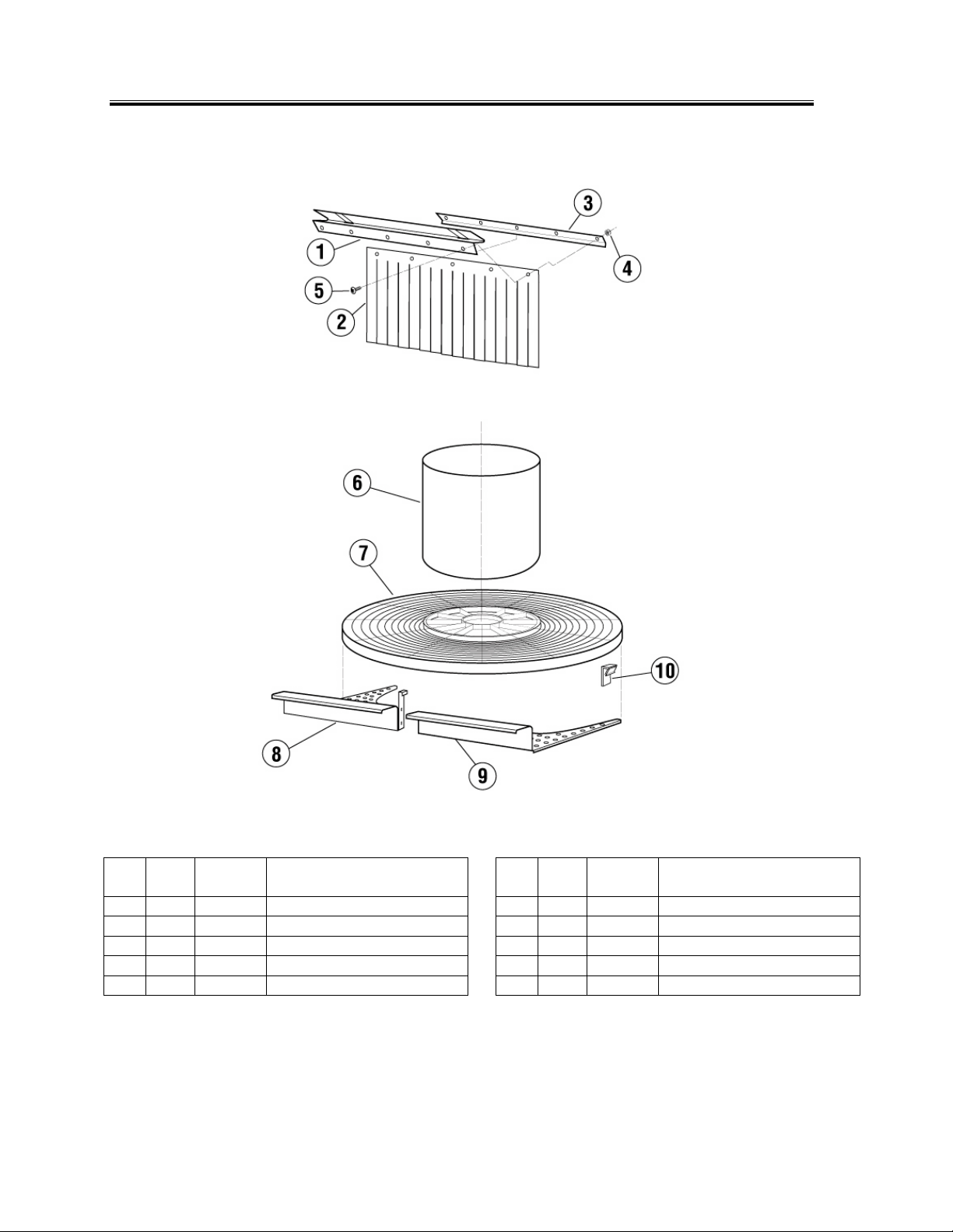
6.2.2. Conveyor Wheel / Curtain
ITEM
MODEL GW-100 Parts MANUAL Rev Rev.1.00 01/17/08 Page5
NO.
NO.
REQ’D
1 1 16505.00 Curtain Support 6 1 16451.00 Conveyor Hub 2” taller
2 1 13703.47 GL-C Curtain 7 1 14750.00 Conveyor Turntable
3 1 16505.10 Curtain Clamp 8 1 16350.50 GW-100 Tray- Left
4 8 00927.00 Nut, 8-32 9 1 16350.00 GW-100 Tray- Right
5 8 00911.50 Screw, 8-32 x 3/8”
P/N DESCRIPTION
ITEM
NO.
NO.
REQ’D
10 4 14750.10 Turntable Glide Block
P/N DESCRIPTION
Page 6

6.2.3. Conveyor Shut-Off Rod Assembly
Parts Manual
MODEL GW-100 Parts MANUAL Rev Rev.1.00 01/17/08 Page6
16 2 00940.50 Truss Head Screw 10-32 x 3/8”
17 1 16320.00 GW-100 Shut-off Rod
18 1 16521.00 Activator
19 1 00935.00 Socket Set Screw, 1/4-20 x 1/4”
20 1 16514.30 Nut Plate
21 1 00472.47 Conveyor Shut Off Switch
22 1 00438.00 Snap Bushing Universal 875-11
23 2 04806.00 #10 Brass Washer
24 2 01001.00 Pan Head Screw 6-32 x 1"
25 1 16514.00 Conveyor Shut Off Switch Brack.
26 2 03814.10 10-32 Lock Star Washer
Page 7

Parts Manual
6.2.4. Control Box Assembly
ITEM
NO.
NO.
REQ’D
1 1 18611.47 GL-C Control Box 14 1 00818.00 GL-C Peri Pump Cover
2 1 00470.10 Toggle Switch Rubber Boot 15 1 16515.00 GL-C Peri Pump Panel
3 3 13417.89 Heater Thermostat (EGO) 16 1 00816.00 GL-C Peri Pump Gear Motor
4 1 13418.49 Auto- Fill Timer 17 1 03470.47 Power on-off/ Flush Switch
5 1 00454.06 Power Block 6 Position 18 4 00438.00 Snap Bushing Universal 875-11
6 3 03475.00 Primer Switch - Push Button 19 3 00839.00 GLC Squeeze Tube w/ conn.
7 3 00820.00 GL-C Peri Pump Circuit Board 20 3 03826.47 4-40x3/16 Pan Head Screw
8 1 16504.00 GL-C Control Box Lid 21 3 00820.06 Circuit Board Stand off
9 1 00631.49 Ice Cube Relay 120V, 20A 22 3 00820.07 Circuit Board Stand off Cap
10 2 00631.00 Ice Cube Relay 120V,12A 23 9 00820.10 Circuit Board Spacer Large *
11 3 00821.21 Circuit Board Connector
12 1 00821.00 GL-C Transformer 25 9 00821.11 Circuit Board Spacer Small *
13 1 00815.00 GL-C Peri Pump Complete
P/N DESCRIPTION
ITEM
NO.
NO.
REQ’D
24 3 00820.20 Circuit Board Connector *
P/N DESCRIPTION
*Not shown
MODEL GW-100 Parts MANUAL Rev Rev.1.00 01/17/08 Page7
Page 8

6.2.5. Soap Tank Assembly
Parts Manual
ITEM
NO.
NO.
REQ’D
1 1 03101.49 Hose Clamp #24 12 1 13463.00 Liquid Level Switch
2 1 03106.40 Ribbed Drain Hose 1 1/2" ID 13 1 16545.50 Overflow Drain Tube
3 1 03101.00 Hose Clamp # 16 1" 14 1 00120.00 Thermometer Bi Metal
4 1 03108.60 Transfer Hose 1" Reinforced 15 1 15417.30 1250 W, 120V Heater
5 1 03106.45 Braided Hose 1/2" 16 1 13417.89 Heater Thermostat (EGO)
6 1 03101.47 Hose Clamp #6 17 2 00940.50 10-32 X 3/8” Truss Head Screw
7 1 05012.00 1/2 Cu Ref Tubing (Per Foot) 18 1 16522.00 Heater Cover
8 1 16541.00 Detergent tank 19 1 16579.20 Drain Screen
9 1 16544.00 Detergent Tank Screen 20 1 16579.00 Drain Pan
10 1 16543.00 Detergent Tank Rear Cover 21 2 00906.00 1/4-20 X 1/2" Hexhead Bolt
11 1 16542.00 Detergent Tank Lid 22 1 16530.50 Tank Support
23 1 40116.00 1/4 Comp X 1/4 MIP Ftg (not shown)
P/N DESCRIPTION
ITEM
NO.
NO.
REQ’D
P/N DESCRIPTION
MODEL GW-100 Parts MANUAL Rev Rev.1.00 01/17/08 Page8
Page 9

6.2.6. Water Inlet Plumbing
Parts Manual
ITEM
NO.
NO.
REQ’D
1 2 41015.49 Solenoid Valve 3/8” 115V 5 1 41014.49 GL-C 3/8" Ball Valve
1A 2 41015.77 Flow Washer 6 2 40012.10 GL-C 1/2 Barb x 3/8” MIP Elbow
1B 2 N/A
1C 2 N/A 3/8" Solenoid Valve Cover 8 1 03106.45 Braided Hose 1/2"
1D 2 41015.60 3/8" Solenoid Valve Coil 9 1 40016.00 Brass Cap
2 3 40010.00 GL-C 3/8” MPT Tee 10 1 16525.00 Plumbing Strap
3 2 40017.00 GL-C 1/2 x 3/8” FPT Reducer
4 1 00715.47 GL-C 3/8" Check Valve
P/N DESCRIPTION
3/8" Solenoid Valve Repair Kit
ITEM
NO.
NO.
REQ’D
7 2 03101.47 Hose Clamp #6
11 2 00914.10 1/4-20 x 5/8” Hexhead Bolt
P/N DESCRIPTION
MODEL GW-100 Parts MANUAL Rev Rev.1.00 01/17/08 Page9
Page 10

6.2.7. Sanitizer Plumbing Component Hardware
Parts Manual
ITEM
MODEL GW-100 Parts MANUAL Rev Rev.1.00 01/17/08 Page10
NO.
NO.
REQ’D
1 1 00120.00 Thermometer 9 1 03106.45 1/2" I.D. Braided Hose
2 2 40011.00 3/8" FPT Cross Connector 10 1 03106.47 3/8" I.D. Braided Hose
3 1 40012.00 3/8" MPT x 1/2" 90° Hose Barb 11 1 00434.49 1/2 x 1/2 x 3/8" Tee
4 1 00826.00 Dual Inlet Chemical Injector 12 5 03101.47 7/16" Gear Clamp
5 1 00425.51 Chemical Tubing Blue 13 1 13699.47 Mixing Chamber
5A 1 00425.54 Chemical Tubing White 14 1 41014.47 1/4”MxF Mini Ball Valve
6 1 16526.00 Gauge Bracket 15 1 13605.00 0-30 PSI Pressure Gauge
7 2 00924.00 Lock Washer, 1/4 16 1 40015.00 3/8 x 1/4" Reducer Bushing
8 2 00912.00 Nut, 1/4-20
P/N DESCRIPTION
ITEM
NO.
NO.
REQ’D
P/N DESCRIPTION
Page 11

6.2.8. Vacuum Breaker and Hardware
Parts Manual
ITEM
NO.
NO.
REQ’D
1 1 03624.00 1/2" Vacuum Breaker 2 1 40014.00 1/2" MPT x 1/2" Hose Barb
1A
1B
1C
1D
2 00421.51 6-32 x 1/4” SS Panhead Screw
1 00739.50 Vacuum Breaker Cap
1 03624.25 1/2” Vacuum Breaker Bonnet
1 03623.00 1/2” Vacuum Breaker Repair Kit
P/N DESCRIPTION
ITEM
6 1 40013.00 GL-C 1/2 Barb x 1/2 MPT 90deg
NO.
NO.
REQ’D
3 2 03101.47 7/16" Clamp
4 1 03106.45 1/2" I.D. Braided Hose
5 1 16410.00 Vacuum Breaker Support 2” taller
P/N DESCRIPTION
MODEL GW-100 Parts MANUAL Rev Rev.1.00 01/17/08 Page11
Page 12

6.2.9. GW-100 Wash Pump Assembly
Parts Manual
ITEM
NO.
NO.
REQ’D
1 1 03106.45 1/2" Braided Hose 7 1 00924.50 1/4" SS Washer x 3/4" OD
2 2 03101.47 Hose Clamp #6 8 1 16370.75 GW-100 Wash Motor Base
3 1 00434.47 Pump Hose Adapter 9 4 00911.50 8-32 X 3/8 Pan Head Screw
4 1 03101.00 Hose Clamp #16 10 1 00201.49 Wash Pump 115 V
5 1 03108.60 Transfer Hose 1" Reinforced
6 2 00914.10 1/4-20 X 5/8 Hexhead Bolt
P/N DESCRIPTION
ITEM
NO.
NO.
REQ’D
11 1 03106.47 3/8" Braided Hose
P/N DESCRIPTION
MODEL GW-100 Parts MANUAL Rev Rev.1.00 01/17/08 Page12
Page 13

6.2.10 Conveyor Drive Assembly
Parts Manual
ITEM
MODEL GW-100 Parts MANUAL Rev Rev.1.00 01/17/08 Page13
NO.
NO.
REQ’D
1 1 14751.00 Drive Gear 5 1 00438.00 Snap Bushing Universal 875-11
2 1 00104.83 VA Drain Motor Shaft Gasket 6 4 00940.50 Screw, 10-32 x 3/8”
3 1 16570.50 Drive Motor Housing 7 1 00810.49 Drive Motor
4 1 00811.47 Extension Spring
P/N DESCRIPTION
ITEM
NO.
NO.
REQ’D
8 1 16570.60 Drive Motor Housing Cover
P/N DESCRIPTION
Page 14

6.2.11 GW-100 Waste Collector Assy.
Parts Manual
MODEL GW-100 Parts MANUAL Rev Rev.1.00 01/17/08 Page14
ITEM
NO.
NO.
REQ’D
1 1 16562.00 GL-C Waste Collector Screen
2 1 16560.00 GL-C Waste Collector Tray
3 1 06231.56 GW-100 Label
4 1 03106.51 Clear Vinyl Tubing 1/2” ID x 3/4”OD
5 1 00899.01 Cleaning Drill not shown
6 1 00899.02 Cleaning Brush not shown
P/N DESCRIPTION
 Loading...