


Model 50.5X
Owner’s Guide

limited lifetime consumer warranty
Directed Electronics ("Directed") promises to the original purchaser to repair or replace with a comparable reconditioned model any Directed unit (hereafter the "unit"), excluding without limitation the siren, the remote transmitters, the associated sensors and accessories, which proves to be defective in workmanship or material under reasonable use during the lifetime of the vehicle provided the following conditions are met: the unit was professionally installed and serviced by an authorized Directed dealer; the unit will be professionally reinstalled in the vehicle in which it was originally installed by an authorized Directed dealer; and the unit is returned to Directed, shipping prepaid with a legible copy of the bill of sale or other dated proof of purchase bearing the following information: consumer's name, telephone number and address; the authorized dealers name, telephone number and address; complete product description, including accessories; the year, make and model of the vehicle; vehicle license number and vehicle identification number. All components other than the unit, including without limitation the siren, the remote transmitters and the associated sensors and accessories, carry a one-year warranty from the date of purchase of the same. This warranty is non-transferable and is automatically void if: the original purchaser has not completed the warranty card and mailed it within ten (10) days of the date of purchase to the address listed on the card; the unit's date code or serial number is defaced, missing or altered; the unit has been modified or used in a manner contrary to its intended purpose; the unit has been damaged by accident, unreasonable use, neglect, improper service, installation or other causes not arising out of defects in materials or construction. The warranty does not cover damage to the unit caused by installation or removal of the unit. Directed, in its sole discretion, will determine what constitutes excessive damage and may refuse the return of any unit with excessive damage. TO THE MAXIMUM EXTENT ALLOWED BY LAW, ALL WARRANTIES, INCLUDING BUT NOT LIMITED TO EXPRESS WARRANTY, IMPLIED WARRANTY, WARRANTY OF MERCHANTABILITY, FITNESS FOR PARTICULAR PURPOSE AND WARRANTY OF NON-INFRINGEMENT OF INTELLECTUAL PROPERTY, ARE EXPRESSLY EXCLUDED; AND DIRECTED NEITHER ASSUMES NOR AUTHORIZES ANY PERSON OR ENTITY TO ASSUME FOR IT ANY DUTY, OBLIGATION OR LIABILITY IN CONNECTION WITH ITS PRODUCTS. DIRECTED DISCLAIMS AND HAS ABSOLUTELY NO LIABILITY FOR ANY AND ALL ACTS OF THIRD PARTIES INCLUDING ITS AUTHORIZED DEALERS OR INSTALLERS. DIRECTED SECURITY SYSTEMS, INCLUDING THIS UNIT, ARE DETERRENTS AGAINST POSSIBLE THEFT. DIRECTED IS NOT OFFERING A GUARANTEE OR INSURANCE AGAINST VANDALISM, DAMAGE OR THEFT OF THE AUTOMOBILE, ITS PARTS OR CONTENTS; AND HEREBY EXPRESSLY DISCLAIMS ANY LIABILITY WHATSOEVER, INCLUDING WITHOUT LIMITATION, LIABILITY FOR THEFT, DAMAGE AND/OR VANDALISM. THIS WARRANTY DOES NOT COVER LABOR COSTS FOR MAINTENANCE, REMOVAL OR REINSTALLATION OF THE UNIT OR ANY
© 2006 directed electronics—all rights reser ved |
i |
CONSEQUENTIAL DAMAGES OF ANY KIND. IN THE EVENT OF A CLAIM OR A DISPUTE INVOLVING DIRECTED OR ITS SUBSIDIARY, THE PROPER VENUE SHALL BE SAN DIEGO COUNTY IN THE STATE OF CALIFORNIA. CALIFORNIA STATE LAWS AND APPLICABLE FEDERAL LAWS SHALL APPLY AND GOVERN THE DISPUTE. THE MAXIMUM RECOVERY UNDER ANY CLAIM AGAINST DIRECTED SHALL BE STRICTLY LIMITED TO THE AUTHORIZED DIRECTED DEALER'S PURCHASE PRICE OF THE UNIT. DIRECTED SHALL NOT BE RESPONSIBLE FOR ANY DAMAGES WHATSOEVER, INCLUDING BUT NOT LIMITED TO, ANY CONSEQUENTIAL DAMAGES, INCIDENTAL DAMAGES, DAMAGES FOR THE LOSS OF TIME, LOSS OF EARNINGS, COMMERCIAL LOSS, LOSS OF ECONOMIC OPPORTUNITY AND THE LIKE. NOTWITHSTANDING THE ABOVE, THE MANUFACTURER DOES OFFER A LIMITED WARRANTY TO REPLACE OR REPAIR THE CONTROL MODULE AS DESCRIBED ABOVE. Some states do not allow limitations on how long an implied warranty will last or the exclusion or limitation of incidental or consequential damages. This warranty gives you specific legal rights and you may also have other rights that vary from State to State.
This product may be covered by a Guaranteed Protection Plan ("GPP"). See your authorized Directed dealer for details of the plan or call Directed Customer Service at 1-800- 876-0800. Directed security systems, including this unit, are deterrents against possible theft. Directed is not offering a guarantee or insurance against vandalism, damage or theft of the automobile, its parts or contents; and hereby expressly disclaims any liability whatsoever, including without limitation, liability for theft, damage and/or vandalism. Directed does not and has not authorized any person or entity to create for it any other obligation, promise, duty or obligation in connection with this security system.
Make sure you have all of the following information from your dealer:
A clear copy of the sales receipt, showing the following:
Date of purchase
Your full name and address
Authorized dealer's company name and address
Type of alarm installed
Year, make, model and color of the automobile
Automobile license number
Vehicle identification number
All security options installed on automobile
Installation receipts
ii
© 2006 directed electronics—all rights reser ved

table of contents
limited lifetime consumer warranty . . . . . . . . . . . . . . . . . . . . . . . . . . . . . . . . . . . . . . . . . i standard transmitter configuration . . . . . . . . . . . . . . . . . . . . . . . . . . . . . . . . . . . . . . . . . 3 what is included . . . . . . . . . . . . . . . . . . . . . . . . . . . . . . . . . . . . . . . . . . . . . . . . . . . . . . . 4 important information . . . . . . . . . . . . . . . . . . . . . . . . . . . . . . . . . . . . . . . . . . . . . . . . . . 4 your warranty. . . . . . . . . . . . . . . . . . . . . . . . . . . . . . . . . . . . . . . . . . . . . . . . . . . . . 5 fcc/id notice . . . . . . . . . . . . . . . . . . . . . . . . . . . . . . . . . . . . . . . . . . . . . . . . . . . . . . 5 caution . . . . . . . . . . . . . . . . . . . . . . . . . . . . . . . . . . . . . . . . . . . . . . . . . . . . . . . . . . 6 remote control diagram. . . . . . . . . . . . . . . . . . . . . . . . . . . . . . . . . . . . . . . . . . . . . . . . . . 7 standard remote configuration . . . . . . . . . . . . . . . . . . . . . . . . . . . . . . . . . . . . . . . . . . . . 8 system maintenance . . . . . . . . . . . . . . . . . . . . . . . . . . . . . . . . . . . . . . . . . . . . . . . . . . . . 9 transmitter functions. . . . . . . . . . . . . . . . . . . . . . . . . . . . . . . . . . . . . . . . . . . . . . . . . . . 10 standard configuration . . . . . . . . . . . . . . . . . . . . . . . . . . . . . . . . . . . . . . . . . . . . . 10 standard icon configurations . . . . . . . . . . . . . . . . . . . . . . . . . . . . . . . . . . . . . . . . 12 remote operation and programming instructions . . . . . . . . . . . . . . . . . . . . . . . . . . . . . 15 system signal paging features . . . . . . . . . . . . . . . . . . . . . . . . . . . . . . . . . . . . . . . . 15 programmable remote control features . . . . . . . . . . . . . . . . . . . . . . . . . . . . . . . . . 17 using your system . . . . . . . . . . . . . . . . . . . . . . . . . . . . . . . . . . . . . . . . . . . . . . . . . . . . 18 warning! safety first . . . . . . . . . . . . . . . . . . . . . . . . . . . . . . . . . . . . . . . . . . . . . . . 18 active arming . . . . . . . . . . . . . . . . . . . . . . . . . . . . . . . . . . . . . . . . . . . . . . . . . . . . 21 passive arming . . . . . . . . . . . . . . . . . . . . . . . . . . . . . . . . . . . . . . . . . . . . . . . . . . . 21 multi-level security arming. . . . . . . . . . . . . . . . . . . . . . . . . . . . . . . . . . . . . . . . . . 23 arming while driving . . . . . . . . . . . . . . . . . . . . . . . . . . . . . . . . . . . . . . . . . . . . . . 24 disarming . . . . . . . . . . . . . . . . . . . . . . . . . . . . . . . . . . . . . . . . . . . . . . . . . . . . . . . 24 high security disarm . . . . . . . . . . . . . . . . . . . . . . . . . . . . . . . . . . . . . . . . . . . . . . . 24 disarming without a transmitter . . . . . . . . . . . . . . . . . . . . . . . . . . . . . . . . . . . . . . 25 silent mode. . . . . . . . . . . . . . . . . . . . . . . . . . . . . . . . . . . . . . . . . . . . . . . . . . . . . . 26 panic mode . . . . . . . . . . . . . . . . . . . . . . . . . . . . . . . . . . . . . . . . . . . . . . . . . . . . . 26 valet mode . . . . . . . . . . . . . . . . . . . . . . . . . . . . . . . . . . . . . . . . . . . . . . . . . . . . . . 27 remote start . . . . . . . . . . . . . . . . . . . . . . . . . . . . . . . . . . . . . . . . . . . . . . . . . . . . . 27 valet take-over . . . . . . . . . . . . . . . . . . . . . . . . . . . . . . . . . . . . . . . . . . . . . . . . . . . 29 short-run/turbo . . . . . . . . . . . . . . . . . . . . . . . . . . . . . . . . . . . . . . . . . . . . . . . . . . 30 timer mode . . . . . . . . . . . . . . . . . . . . . . . . . . . . . . . . . . . . . . . . . . . . . . . . . . . . . 31 rear defogger . . . . . . . . . . . . . . . . . . . . . . . . . . . . . . . . . . . . . . . . . . . . . . . . . . . . 32
safety features . . . . . . . . . . . . . . . . . . . . . . . . . . . . . . . . . . . . . . . . . . . . . . . . . . . . . . . . 33 starter anti-grind circuitry . . . . . . . . . . . . . . . . . . . . . . . . . . . . . . . . . . . . . . . . . . 33 disabling the remote start system . . . . . . . . . . . . . . . . . . . . . . . . . . . . . . . . . . . . . 34 over and under rev protection . . . . . . . . . . . . . . . . . . . . . . . . . . . . . . . . . . . . . . . 34 shut down inputs . . . . . . . . . . . . . . . . . . . . . . . . . . . . . . . . . . . . . . . . . . . . . . . . . 35 nuisance prevention circuitry . . . . . . . . . . . . . . . . . . . . . . . . . . . . . . . . . . . . . . . . 35
diagnostics . . . . . . . . . . . . . . . . . . . . . . . . . . . . . . . . . . . . . . . . . . . . . . . . . . . . . . . . . . 36
© 2006 directed electronics—all rights reser ved |
1 |
arming diagnostics . . . . . . . . . . . . . . . . . . . . . . . . . . . . . . . . . . . . . . . . . . . . . . . 36 disarming diagnostics . . . . . . . . . . . . . . . . . . . . . . . . . . . . . . . . . . . . . . . . . . . . . 37 system status chirps . . . . . . . . . . . . . . . . . . . . . . . . . . . . . . . . . . . . . . . . . . . . . . 38 table of zones . . . . . . . . . . . . . . . . . . . . . . . . . . . . . . . . . . . . . . . . . . . . . . . . . . . 39 interpreting zone diagnostics . . . . . . . . . . . . . . . . . . . . . . . . . . . . . . . . . . . . . . . 39
code hopping . . . . . . . . . . . . . . . . . . . . . . . . . . . . . . . . . . . . . . . . . . . . . . . . . . . . . . . 40 high frequency . . . . . . . . . . . . . . . . . . . . . . . . . . . . . . . . . . . . . . . . . . . . . . . . . . . . . . 41 owner recognition . . . . . . . . . . . . . . . . . . . . . . . . . . . . . . . . . . . . . . . . . . . . . . . . . . . 41 rapid resume logic . . . . . . . . . . . . . . . . . . . . . . . . . . . . . . . . . . . . . . . . . . . . . . . . . . . . 42 power saver mode . . . . . . . . . . . . . . . . . . . . . . . . . . . . . . . . . . . . . . . . . . . . . . . . . . . . 42 programming remote control features . . . . . . . . . . . . . . . . . . . . . . . . . . . . . . . . . . . . . 43
To enter programming mode . . . . . . . . . . . . . . . . . . . . . . . . . . . . . . . . . . . . . . . 43 To exit programming mode . . . . . . . . . . . . . . . . . . . . . . . . . . . . . . . . . . . . . . . . 43 Page notification (Beep or Vibrate). . . . . . . . . . . . . . . . . . . . . . . . . . . . . . . . . . . 43 Illumination (On or Off) . . . . . . . . . . . . . . . . . . . . . . . . . . . . . . . . . . . . . . . . . . 43 Sensor icon selection (hood/trunk). . . . . . . . . . . . . . . . . . . . . . . . . . . . . . . . . . . 43 Page mode (On/Off) . . . . . . . . . . . . . . . . . . . . . . . . . . . . . . . . . . . . . . . . . . . . . 44
programming options . . . . . . . . . . . . . . . . . . . . . . . . . . . . . . . . . . . . . . . . . . . . . . . . . 44 glossary of terms . . . . . . . . . . . . . . . . . . . . . . . . . . . . . . . . . . . . . . . . . . . . . . . . . . . . . 49 quick reference guide. . . . . . . . . . . . . . . . . . . . . . . . . . . . . . . . . . . . . . . . . . . . . . . . . . 51
2 |
© 2006 directed electronics—all rights reser ved |
standard transmitter configuration
controls the Arm and Panic On/Off function.
 controls the Disarm and Panic Off function.


 controls Silent Mode™ and Auxiliary channel 2 output.
 controls the Remote Start function.
and |
pressed together control the Timer mode. |
|
and |
pressed together control Turbo/Short Run. |
|
and |
pressed together control channel 4 output. |
|
and |
pressed together control channel 5 output. |
|
and |
and |
pressed together control the rear |
|
|
defogger. |
and |
pressed together control channel 6 output. |
|
© 2006 directed electronics—all rights reser ved |
3 |

what is included
A control module
SST 2-way receiver/antenna
One four-button transmitter
A Stinger™ DoubleGuard® two-stage shock sensor
A Revenger™ Soft Chirp™ six-tone programmable siren
A blue status LED indicator light
A push-button Valet switch
Your warranty registration
A shut-down toggle switch
important information
Congratulations on the purchase of your combination remote start alarm system. Due to the complexity of this system, it must be installed by an authorized dealer only. Installation of this product by anyone other than an authorized dealer voids the warranty. All dealers are provided with a preprinted dealer certificate to verify authorization.
By carefully reading this Owner's Guide prior to using your system, you will maximize the use of this system and its features. You can print additional or replacement copies of this manual by accessing our web site at www.directed.com.
4 |
© 2006 directed electronics—all rights reser ved |

your warranty
Your warranty registration must be completely filled out and returned within 10 days of purchase. Your product warranty will not be validated if your warranty registration is not returned. Make sure you receive the warranty registration from your dealer. It is also necessary to keep your proof of purchase, which reflects that the product was installed by an authorized dealer.
fcc/id notice
This device complies with Part 15 of FCC rules. Operation is subject to the following two conditions: (1) This device may not cause harmful interference, and (2) This device must accept any interference received, including interference that may cause undesirable operation.
Changes or modifications not expressly approved by the party responsible for compliance could void the user's authority to operate this device.
IVU, In vehicle receiver unit
To satisfy FCC RF exposure compliance the device and its antenna must maintain a separation distance of 20 cm or more from a person’s body, except for the hand and wrists, to satisfy RF exposure compliance.
HHU, hand held unit
To satisfy FCC RF exposure compliance requirements, this device should be used in hand-held, hand operated configurations only. The device and its antenna must maintain
© 2006 directed electronics—all rights reser ved |
5 |

a separation distance of 20 cm or more from the person’s body, except for the hand and wrists, to satisfy RF exposure compliance. This device is designed to be used in a person’s hands and its operating configurations do not support normal transmissions while it is carried in pockets or holsters next to a persons’ body.
caution
This product is designed for fuel injected, automatic transmission vehicles only. Use of this product in a standard transmission vehicle is dangerous and contrary the product's intended use.
6 |
© 2006 directed electronics—all rights reser ved |

remote control diagram
note:The Program button is located on the back of the remote.
© 2006 directed electronics—all rights reser ved |
7 |
standard remote configuration
1.Auxiliary Channel Out
2.Receive Indicator
3.Signal Indicator
4.Transmit Indicator
5.Lock Status Indicator
6.Unlock Status Indicator
7.Arming Status Indicator
8.Disarming Status Indicator
9.Door Switch Input Indicator
10.Warn Away® Response Indicator
11.Siren Status Indicator
12.Battery Level Indicator
13.Trigger Response Indicator
14.Hood Switch Input Indicator
15.Ignition Switch Input Indicator
16.Sensor Response Indicator
17.Sensor 1 Indicator—Full Trigger and Warn Away®
18.Sensor 2 Indicator—Full Trigger and Warn Away®
19.Trunk Switch Input Indicator
20.Vibrate Mode Indicator
21.Remote Start Indicator
22.Disarm Button
23.Remote Start Button
24.Auxiliary Button
25.Arm Button
8 |
© 2006 directed electronics—all rights reser ved |
system maintenance
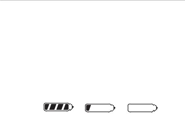
This system needs no specific maintenance beyond remote control battery replacement. The remote is powered by a 1.5V AAA battery.
The Battery Level indicator has four level indicators that serve as a visual indication of battery charge. When the battery reaches a low charge level that requires replacement, the remote control will generate a single notification chirp, and the Battery Level indicator will flash continuously.
FULL |
REPLACE |
EMPTY |
Battery Replacement
Gently pull the end of the battery door away from the top of the remote control then slide the door up to expose the battery and remove the expired battery. Place the new battery into the remote control observing the correct polarity. When power is returned the remote control will light all icons in the LCD and generate all beeper tones once.
© 2006 directed electronics—all rights reser ved |
9 |

transmitter functions
The receiver uses a computer-based Learn Routine to learn the transmitter buttons. This makes it possible to assign any remote transmitter button to any receiver function. The transmitter initially comes programmed with Standard Configuration, but may also be customized by an authorized dealer. The buttons in all of the instructions in this manual correspond to a Standard Configuration transmitter.
standard configuration


 Button
The arming function is controlled by pressing this button for one second. Pressing and holding this button for more than 3 seconds will trigger the panic mode.


 Button
The disarming function is controlled by pressing this button for one second. Pressing this button during panic mode will turn off the panic mode.


 Button
Silent Mode™ and an optional auxiliary function are controlled by this button. (Silent Mode works by pressing this button for less than one second before arming or disarming. An optional auxiliary function, such as trunk release, can be controlled by pressing this button for 1.5 seconds.)
The auxiliary output controls __________________________.
10 |
© 2006 directed electronics—all rights reser ved |


 Button
The remote start feature is turned On/Off by pressing this button twice.


 and
and 

 Buttons
The remote start timer mode function of the system is controlled by pressing these buttons simultaneously.


 and
and 

 Buttons
The Turbo/Short Run feature is controlled by these buttons (refer to the Turbo/Short Run section for additional details).


 and
and 

 Buttons
An optional auxiliary convenience or expansion function that you have added to your system can be activated by pressing these buttons simultaneously.
The auxiliary output controls __________________________.


 and
and 

 Buttons
An optional auxiliary convenience or expansion function that you have added to your system can be activated by pressing these buttons simultaneously.
The auxiliary output controls __________________________.


 and
and 

 and
and 

 Buttons
When simultaneously pressed these buttons control the rear window defogger during remote starting.
© 2006 directed electronics—all rights reser ved |
11 |


 and
and 

 Buttons
An optional auxiliary convenience or expansion function that you have added to your system can be activated by pressing these buttons simultaneously.
The auxiliary output controls __________________________.
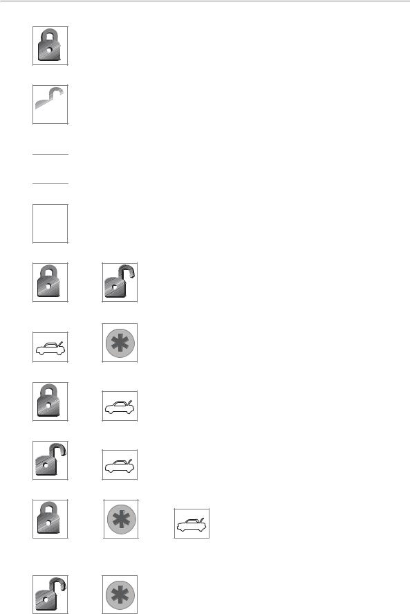
standard icon configurations


 Icon
Icon
The transmit icon will be displayed while the remote control is transmitting a command to the vehicle.


 Icon
Icon
The receive icon will be displayed while the remote control is receiving a page from the vehicle.
Icon
The signal icon will be displayed if a command is transmitted to the vehicle but a command page is not received.

 Icon
Icon
The armed status icon will be displayed when the system is locked and armed.
Icon
The disarmed status icon will be displayed when the system is unlocked and disarmed.


 Icon
Icon
The disarm icon will flash while the system is disarming.
12 |
© 2006 directed electronics—all rights reser ved |


 Icon
Icon
The arm icon will flash while the system is arming.

 Icon
Icon
The door icon will be displayed to indicate that a door is open when arming the system (Bypass Notification) or opened when the system is armed (Tamper Alert).


 Icon
Icon
The warn icon will be displayed if the Warn Away® response has been triggered while the system is armed.


 Icon
Icon
The siren icon will be displayed as an indicator that the siren is sounding.


 Icon
Icon
The alarm icon will be displayed if the system has been violated, and will continue to be displayed until the 60-second siren cycle is complete.


 Icon
Icon
The vibrate icon will be displayed when the Vibrate Mode is on.
 Icon
Icon
The battery level icon is always displayed as an indicator of Battery charge.
Icon
The start icon will be displayed while the vehicle is remote started.
© 2006 directed electronics—all rights reser ved |
13 |
note: If Page Mode has been turned off, the start icon will remain when performing key take over until a button on the transmitter has been pressed.


 Icon
Icon
The trunk icon will be displayed to indicate that the trunk is open when arming the system (Bypass Notification) or opened when the system is armed (Tamper Alert).


 Icon
Icon
The Sensor 1 icon will be displayed if the Dual-Stage shock sensor has been triggered as a full-triggered or Warn Away® sequence.


 Icon
Icon
The Sensor 2 icon will be displayed if an additional Dual-Stage sensor has been triggered as a full-triggered or Warn Away® sequence.


 Icon
Icon
The hammer icon will flash when either Sensor 1 or 2 has been triggered as either a Warn Away® response or triggered sequence.


 Icon
Icon
The ignition icon will be displayed to indicate that the ignition is on when arming the system (Bypass Notification) or turned on when the system is armed (Tamper Alert).

 Icon
Icon
The hood icon will be displayed to indicate that the hood is open when arming the system or (Bypass Notification) opened when the system is armed (Tamper Alert).
14 |
© 2006 directed electronics—all rights reser ved |

Number Icons
When either of the channel 2, 4 or 5 outputs is activated the
appropriate icon will be displayed for five seconds.
remote operation and programming instructions
The remote start system operates at 434 MHz and incorporates Directed’s proprietary XHF2 out-board ResponderTechnology remote control. The high frequency combined with Binary Data communication achieves superior range with two-way communication.
system signal paging features
A page is the signal the control module sends to the remote control as confirmation of receipt of a command or alarm system status.
When the remote control receives a page it will generate a page notification to the user (notifications are audible beeps or remote vibration) and the LCD Icons will display the current system status.
Command Page
When a command (arm/disarm, remote start, or auxiliary channel) from the remote control is sent and received, the system will send a command page back to confirm receipt.
note: When the system is in Valet mode, the remote control will show the lock (5) and unlock (6) icons, but will not generate a command page.
© 2006 directed electronics—all rights reser ved |
15 |
 Loading...