


330.3X
The company behind Clifford® Auto Security Systems
is Directed Electronics.
Vista, CA 92081
www.clifford.com
2009 Directed Electronics, All rights reserved. G3303X 2009 11
©
Since its inception, Directed Electronics has had one
purpose, to provide consumers with the finest vehicle
security and car stereo products and accessories
available. The recipient of nearly 100 patents and
Innovations Awards in the field of advanced electronic
technology, Directed Electronics is ISO 9001 registered.
Quality Directed Electronics products are sold and serviced
throughout North America and around the world.
Call (800) 876-0800 for more information about our
products and ser vic es.
THE SCIENCE OF SECURITY
™
Directed Electronics is an
ISO 9001 registered company.
Directed Electronics is committed to delivering
world class quality products and services that
excite and delight our customers.
OWNER’S GUIDE
MODEL
330.3X
Congratulations
Congratulations on the purchase of your state-of-the-art security system.
Reading this owner’s guide prior to using your system will help maximize the use of your system and its many features. For more information please visit the below website:
http://www.clifford.com – For general and additional guide information.
For any additional questions please contact your authorized Directed
dealer or contact Directed at 1-800-753-0600.
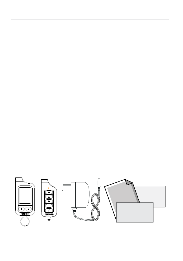
What you get
Welcome to the best generation of vehicle security. Your system contains everything you need.
Responder LC remote controls
1-way companion remote controls
AC adapter for charging your remote controls
This owner’s guides
Quick reference cards
Warranty cards
Owner’s
Guide
AUX
Warranty
Card
Quick
Reference Card
G3303X 2009-11

Important information
Your Warranty
Your system comes with a warranty. Please make sure you receive the
warranty registration card and proof of purchase from your dealer
indicating the product was installed by an authorized Directed dealer.
Your product warranty must be validated within 10 days of purchase.
You can validate it online at www.prodregister.com/directed or com-
plete and return the warranty registration card.
Quick Reference Card
Carry this card with you to reference your system’s many features.
Replacement Remote Controls
If additional remote controls are desired, please see your authorized
dealer or visit us at www.directedstore.com to order. Part numbers
are: 7351X for Responder LC 2-way remote control and 7153X for
the 1-way companion remote control.

Contents
Getting Started .................................................................................................... 4
Charging the Remote Control ................................................................ 4
Keys to using this Manual ..................................................................... 5
Responder LC 2-Way...........................................................................................6
Status Screen Icons ..............................................................................................8
Using your System ............................................................................................. 11
Commands and Confirmations ............................................................ 11
Performing Commands ....................................................................... 11
Responder LC Command table ............................................................ 12
Basic Commands (Direct Access) ........................................................................13
Arm ................................................................................................. 13
Disarm ............................................................................................. 13
AUX/Trunk ........................................................................................ 14
Remote Start /AUX 1/ AUX 4 ............................................................. 14
Advanced Commands: (Level 1) .........................................................................15
Silent Arm ......................................................................................... 15
AUX 1 .............................................................................................. 15
Advanced Commands: (Level 2) .........................................................................16
Sensor Bypass ................................................................................... 16
Remote Valet .................................................................................... 16
AUX 2 .............................................................................................. 16
Advanced Commands: (Level 3) .........................................................................17
Sensor Silent Arm* ............................................................................ 17
AUX 3 .............................................................................................. 17
Alarm Report* ................................................................................... 18
Advanced Commands: (Level 4) .........................................................................19
Full Silent Arm* ................................................................................. 19
AUX 4 .............................................................................................. 19
Responder LC Configuration ............................................................................... 20
Navigating Menus and Options .......................................................... 20
Button Operation ............................................................................... 20
Access Menu Items ............................................................................ 20
Main Menu ....................................................................................................... 21
Setup Remote Menu: .......................................................................... 21
Remote Start Info ............................................................................... 22
Runtime Alert ..................................................................................... 22
Car 2 ............................................................................................... 23
BackLight .......................................................................................... 23
Temp Unit ......................................................................................... 23
Button Beep....................................................................................... 23
System Type ...................................................................................... 23

Clock Set .......................................................................................... 24
Review ............................................................................................. 24
Exit .................................................................................................. 24
Sensor Adjust: ................................................................................... 24
Pair a Responder LC remote control: .................................................... 24
Demo Mode: ..................................................................................... 25
Power Off: ........................................................................................ 26
Exit: ................................................................................................. 26
Alarm Features .................................................................................................27
Normal Arm Protection ....................................................................... 27
Sensor Silent Arm Protection ................................................................ 27
Full Silent Arm Protection .................................................................... 28
Sensor Warn-away Messages ............................................................. 28
Full Trigger Messages ......................................................................... 28
Emergency Override .......................................................................... 28
Trigger Zone Fault Report.................................................................... 29
Alarm Report when Disarming ............................................................. 29
Alarm Report when Requested ............................................................. 30
Nuisance Prevention (NPC) ................................................................. 30
Remote and System Operations .......................................................................... 31
Passive Arming* ................................................................................ 31
Auto Re-arming* ................................................................................ 31
Valet Mode ....................................................................................... 32
Power Save ....................................................................................... 32
Rapid Resume ................................................................................... 32
Automatic Remote Updates ................................................................. 32
Out of Range .................................................................................... 33
No Remote Output ............................................................................. 33
Car Select ......................................................................................... 33
Vehicle Recovery System (VRS) ............................................................ 34
1-way Companion Remote Control ..................................................................... 35
Accessing Commands ........................................................................ 36
Button Auto Lock ................................................................................ 36
Car Select ......................................................................................... 36
Programming .................................................................................... 37
Battery Information (1-way) ................................................................. 38
Low Battery Alerts .............................................................................. 38
Battery Replacement ........................................................................... 38
System Expansion Options ................................................................................. 39
Battery Information (Responder LC) ..................................................................... 41
Low Battery ....................................................................................... 41
Battery Life ........................................................................................ 42
Battery Disposal ................................................................................ 43

Glossary of Terms .............................................................................................. 44
Government Regulations .................................................................................... 46
Additional information ....................................................................................... 47
Interference ....................................................................................... 47
Upgrades and Batteries ...................................................................... 47
Water/Heat Resistance ...................................................................... 47
Limited lifetime consumer warranty ..................................................................... 48

Getting Started
Your remote control is powered by an internal rechargeable battery
that can only be serviced by an authorized Directed dealer. Due to
transit and storage time prior to your purchase, the battery charge
may have depleted. To ensure proper operation, check the battery
level and connect the battery charger if not fully charged. See Bat-
tery Information and Status Screen Icons sections for more information
about the battery.
Charging the Remote Control
Plug the AC adapter into a 110V AC outlet. Insert the mini-USB 1.
connector into the mini-USB port located on the side of the
remote control (see diagram under Responder LC 2-way). The
text field will display
charging (The remote remains operational while charging and
can command the system).
Once fully charged the text field will display 2.
The remote control is then ready for use. Disconnect the mini-3.
USB end from the remote control first and then the AC adapter
from the AC outlet.
The remote control remains operational while charging and
Note
can command the system.
If the battery is excessively depleted when the charger is
connected, functionality may be delayed while it charges to
the minimum voltage required to operate the display, after
which normal charging resumes.
CHARGE
to indicate the remote control is
FULL
.
4
© 2009 Directed Electronics. All rights reserved.

Keys to using this Manual
Specific actions (in bold type) and style conventions are used consistently throughout this manual, they are as follows:
Press: s implies pushing in and releasing a button.
Hold: s is used after “press” actions when a button needs to be
held in position for an extended period of time, typically several
seconds.
ARMED
s this style denotes the text which appears in the text field
portion of the display during operations described in the manual.
If the text string is too long for the text field, it then plays and loops
sequentially word by word.
Italicizeds words denote section/sub headings in this guide and
can be located through the table of contents.
An asterisk (*) when used after a word or phrase denotes that s
additional details can be found in related sections usually noted
at the bottom of the page or end of the section.
© 2009 Directed Electronics. All rights reserved.
5
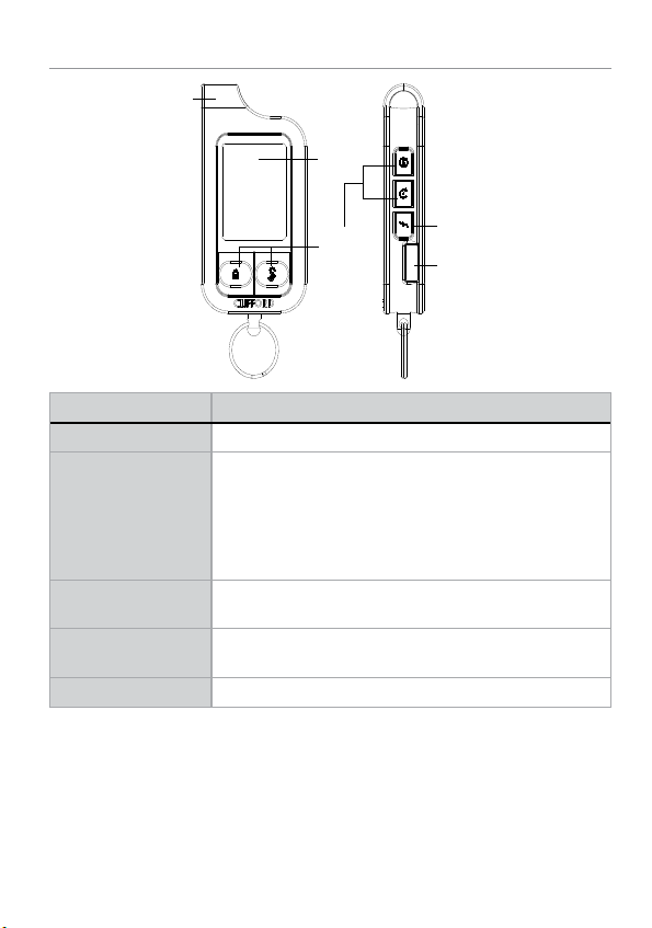
Responder LC 2-Way
Internal
Antenna
Display
Command
Buttons
Feature Description
Internal Antenna Used for transmitting and receiving information
Display Status screen - the upper portion of the display contains status
Command Buttons (4) Used to perform arming, disarming and auxiliary channel
Function Button Used to access function levels for commands, configuration
Mini-USB Port The battery charger plugs into this port
icons for the system, siren, alarm zones, and remote control
Text field - the lower portion of display shows the clock,
command confirmations, page messages and programming
menus
commands
menus for programming, and car selection
Function Button
Mini-USB Port
6
© 2009 Directed Electronics. All rights reserved.
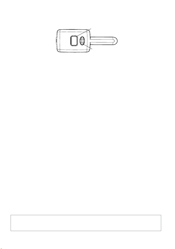
Control Center
Control Center
Button
Control Center
LED
The control center, typically located on the upper part of the front
windshield sends and receives commands or messages to and from
your system. It consists of:
The In-vehicle system antenna, for 2 way communication. s
The control center LED, as a visual indicator of the system’s sta-s
tus.
The control center button, for placing the system into valet mode* s
and to perform the emergency override** operation.
* See Remote and System Operations section for details.
** See
Alarm Features for details.
© 2009 Directed Electronics. All rights reserved.
7
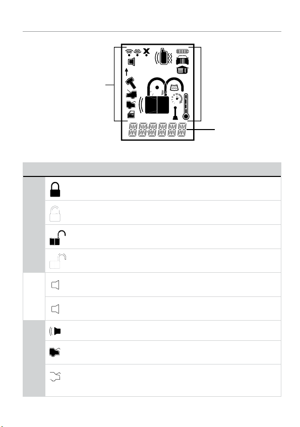
Status Screen Icons
ALL
Status Screen
Icons
The table below describes all the status screen icons.
Icon Description
Armed: The system is armed, the alarm is enabled
Locked: The system is locked in valet, the alarm is disabled
1
Text Field
System Status
Siren Status
Zone Status
8
Disarmed: The system is disarmed, the alarm is disabled
Unlocked: The system is unlocked in valet, the alarm is disabled
Siren is disabled for sensor triggers; remote is paged for all triggers (sensor silent arm)
Siren is disabled for all triggers; remote is paged for all triggers
+ ALL
(full silent arm)
On during warn-away and full trigger message output
On during trunk zone full trigger output and aux/trunk channel
activation
On during fault report to indicate the trunk is open and
bypassed when arming
© 2009 Directed Electronics. All rights reserved.
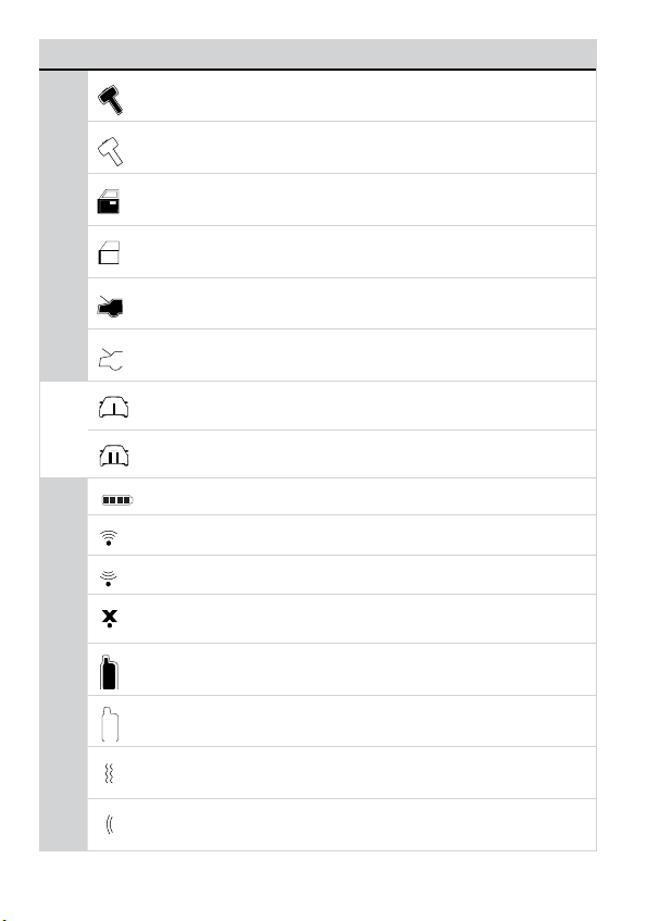
Icon Description
On during a sensor zone full trigger output
On during fault report to indicate a sensor is active and
bypassed when arming
On during the door zone full trigger output
Zone Status
On during fault report to indicate a door is open and bypassed
when arming
On during a hood zone full trigger output
On during fault report to indicate the hood is open and
bypassed when arming
On when remote is set to command the system programmed
as car 1*
On when remote is set to command the system programmed
as car 2*
Bars indicate battery level is full, ¾,½,¼ or empty
On while the remote control is transmitting a command
On while the remote control is receiving a message
On with out of range fault tone to indicate the remote failed to
receive a command confirmation
Pager on: The remote will wake up to listen for messages
Remote Control Status
Pager off: The remote will not wake up to listen for messages
The remote will vibrate when messages are received
The remote will emit beeps and tones when messages are
received
© 2009 Directed Electronics. All rights reserved.
9

Icon Description
Text field Displays the clock, message text and feature menus
On after the garage open** message has been received
On after the garage closed** message has been received
Remote start is active, the engine is running (with optional
remote start module only)
* This icon not present until the car 2 is turned on in the Setup Remote
configuration menu.
** This icon not present until the remote is paired with an optional
garage door opener.
10
© 2009 Directed Electronics. All rights reserved.

Using your System
Commands and Confirmations
Commands, basic or advanced, are used to activate system features and are performed by pressing one of the command buttons.
Basic commands control the most often used security features while
advanced commands control more specialized features and request
reports.
Confirmations for basic or advanced commands are indicated
first by siren chirps and parking light flashes, and then by text, icons
and beeps or tones on the remote control. A description of each
feature confirmation is found in the Basic Commands and Advanced
Commands sections.
Performing Commands
Perform basic commands by pressing one of the command buttons
while in the direct access level. Direct access is available while the
text field displays the clock. Perform advanced commands by first
accessing one of the function Levels and then pressing one of the command buttons while within a level. Function Levels are available when
the text field displays LEVEL 1,2,3 or 4.
Advanced Command example: Silent Arm
Press1. the
field will display
Press2. the
silent arm command.
The Responder LC remote will display 3.
text field and update the status screen icons.
button once to access function level 1, the text
LEVEL 1
.
button while
LEVEL 1
text is still on to perform the
SILENT ARMED
in the
© 2009 Directed Electronics. All rights reserved.
11
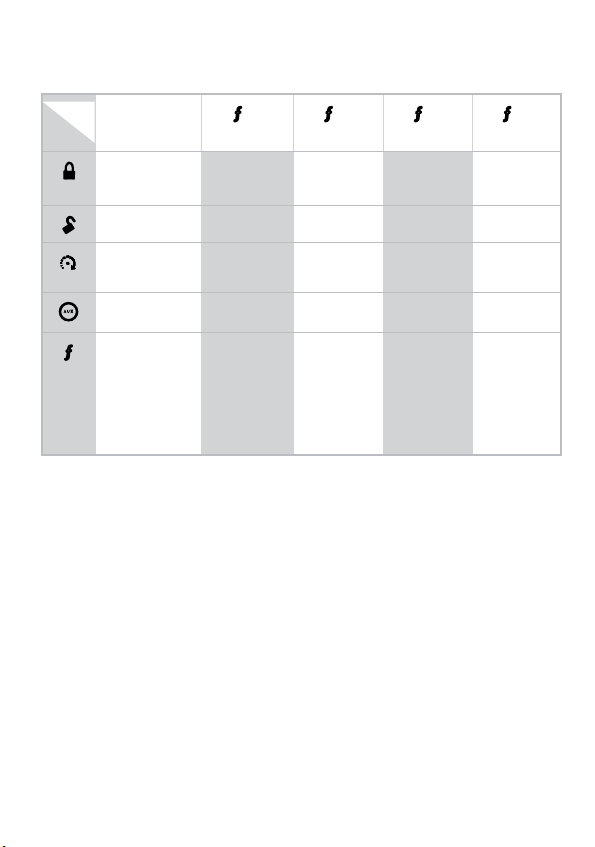
Responder LC Command table
Direct Access
Level
Button
Arm/Lock
(Panic)
Disarm/Unlock Silent Disarm Remote Valet Car Finder
Remote Start*/
Aux 1/4**
Aux/Trunk AUX 1 AUX 2 AUX 3 AUX 4
A U X
x 1
LEVEL 1
Silent Arm Sensor
LEVEL 2
Bypass
x 2
x 3
LEVEL 3
Sensor Silent
Arm
x 4
LEVEL 4
Full Silent
Arm
Advance Level
Change Car
(3s), Enter
programming
(8s)
Alarm
Report
* Available only with optional remote start module installation
** This button can command either aux 1 or aux 4 if turned on by
an authorized Directed dealer.
12
© 2009 Directed Electronics. All rights reserved.

Basic Commands (Direct Access)
Arm
Press and release
6:30
The alarm arms, doors lock (if connected), and the siren
chirps and parking lights flash once. The
to confirm and the system status icons update. If valet mode* is on,
the doors lock and the
VALET
text and tone play. Exit valet mode to
arm the alarm normally.
If a trigger zone fault is detected the siren chirps once again and the
trigger zone fault report** plays.
To Arm and Panic
Press and hold
The alarm arms (or locks in valet) and, after 2 seconds, sounds
the siren and flashes the parking lights. The
siren tones play to confirm. Press the
the output.
Disarm
Press and release
ARMED
text and beeps play
PANIC
or button to stop
text and
The alarm disarms, doors unlock (if connected), and the siren chirps
and parking lights flash twice. The
DISARM
text and beeps play to
confirm and the system status icons update. If valet mode* is on, the
doors unlock and the
VALET
text and tone play.
More than 2 siren chirps and remote beeps indicate a trigger has occurred. The
© 2009 Directed Electronics. All rights reserved.
DISARM
text is replaced by the alarm report.**
13
 Loading...