

Page 1
Cleveland Range
UNITED STATES
CANADA
REPAIR MANUAL
MODEL NO.
2DE24/2DE/2DLE/2DLLE
2DG24/2DG/2DLG/2DLLG 2DS24/2DS
2DSC24/2DSC
Cleveland Range, Inc.
1333 East 179th St.
Cleveland, Ohio 44110
Phone: (216) 481-4900 • FAX: (216) 481-3782
Garland Commercial Ranges • 1777 Kamato Rd.
Mississauga, Ontario CN L4W 1X4
Phone: (416) 624-0260 • FAX: (416) 624-0623
FCS-07
Page 2
Installation Instructions For Steam Generators, Steamers,
Steamer/Kettles: Gas — Electric — Steam Coil
Installation Instructions For All Models
1) These instructions must be retained by the owner / user for future reference. For installation only in noncombustible locations. Gas units
are only to be installed in areas that have provisions for adequate air supply.
2) Position: For proper operation and drainage, steam generator must be level. It must be set near a floor drain. Attach 1 1/2" piping to all
drain connections to carry exhaust steam away from the cabinet Ends of drain lines must vent to atmosphere to avoid back pressure.
Allow a MINIMUM of 6" clearance to the rear and sides of the equipment. The surrounding area must be free and clear of combustibles.
3) Install in accordance with local codes and/or the National Electric Code ANSI/NFPA No. 70-1984. installation in Canada shall be in
accordance with the Canadian Electric Code CSA Standard C22-1 A unit that is connected 10 electricity must be grounded. A wiring
diagram is provided inside the relay box.
4) Connect supply lines for 140° — 160° hot water, and cold water, to the unit. Water pressure must be maintained between 35 and 60 psi.
Locations and pressure data are shown on the connection drawing. Long hot water lines should be at least 1/2" IPS. Rush water supply
lines thoroughly before connecting. Use water which is low in total solids content and low in gas content to prevent internal scaling,
pitting and corrosion of the steam generator and carry-over of minerals into the steam. Water which is fit to drink can still contain highly
detrimental impurities. Refer to Water Quality Requirements page.
5) Turn on water supply to steam generator. Water valve is inside of base.
6) Connect fuel supply
FOR YOUR SAFETY
Do not store or use gasoline or other flammable vapors and liquids in the
vicinity of this or ar., other appliance.
For Steam Coil Steam Generators —
— Connect steam supply: Location is shown on the connection drawing. Incoming steam pressur e must be regulated between 35 and
45psi (30 — 45 psi for pressure steamers). Install a strainer ahead of the regulating valve. Rush line thoroughly before connecting.
— Connect the outlet end of the steam coil to an inverted bucket trap. Pill trap with water before installing.
— Connect electricity if unit is equipped with electrical controls. Permanent 115V connection is required. Junction box location is
shown on the connection drawing. Unit must be electrically grounded by the installer.
For Gas Fired Generators—
— Post, in a prominent location, instructions to be followed in the event the user smells gas. This information shall be
obtained by consulting the local gas supplier.
— Connect gas: Location and pressure data are shown on the connection drawing. Installation shall be in accord ance with local codes, or
in the absence of local codes, with the National Fuel Gas Code, ANSI 2223.1 —1984 Installation in Canada shall be in accordance
with Installation Codes for Gas Burning Appliances and Equipment B1 49.1 and B149.2. Use a gas pipe joint compound, which is
resistant to LP gas. Test all pipe joints for leaks with soap and water solution. Allow 12 inch clearance on right side of all Gas Fired
Steam Generator models for servicing gas burners and for proper operation. This 12" clearance also provides adequate air openings
into the combustion chamber. Never obstruct the flow of combustion and ventilation air. The appliance and its individual shutoff
valve must be disconnected from the gas supply piping system during any pressure testing of that system at test pressures in excess of
V1/2 psig (3-45 kPa). The appliance must be isolated from the gas supply piping system by closing its individual manual shutoff
valve during any pressure testin g of the gas supply piping system at test pressure equal to or less than % psig (3.45 kPa).
— Connect electricity if unit is equipped with electrical controls. Permanent 115V connection is required- Junction box location is
shown on the connection drawing. Unit must be electrically grounded by the installer.
----Lighting and Shutdown Instructions: Flip electrical switch on. Open water valve. Open gas valve. Slightly depress and turn control
knob to "off" for 5 minutes before lighting gas. Turn control knob to "pilot", depress it completely and light pilot burner. Continue to
hold knob in for about 60 seconds, then release. Pilot burner is lighted through hole in panel at bottom of steam generator. Never
leave panel oft. as this will damage controls. Turn control knob to "on". Depress electrical "reset" switch for main burner ignition.
Burners will not light without water in the steam generator. For main burner off, with pilot on, turn control knob to "pilot". For main
and pilot burner off., slightly depress and turn control knob to "off". Flip electrical switch off.
For Electrical Steam Generators —
— Connect electric power Location is shown on the connection drawing. Provide connection as required by your unit. Electric supply
must match power requirements specified on data plate attached to base. Wiring must be adequate to carry required current at rated
voltage. A separate fused disconnect must be supplied and installed. Unit must be electrically grounded by the installer.
—
1066 LITHO IN U.S.A. Manufacturer reserves right of design improvement or modification, as warranted
CLEVELAND RANGE CO., 1333 EAST 179th ST., CLEVELAND, OHIO 44110
Page 3
data— sheet— 260-LB-2 (R2)
7) Turn on electricity at control circuit switch on steamer console. A red light glows when electricity is on. If water level is correct, steam
generator will operate by pressing the "reset" button. Heaters will not work without water in the steam generator. This manual reset button
must be pressed to start up the generator initially, and to restart the steam generator after every shut oft. or power interruption. No attempt
should be made to operate the equipment during a power failure.
8) Check to make sure that the water in the sight gauge glass automatically stays at about 2/3 full when the unit is started up.
9) When installation is complete and free of leaks, refer to Operating Procedures sheet
Instructions For Steam Generator Care
Protect your steam generator, prolong its life and preserve its performance by giving it the required daily attention, on a regular schedule. Follow
servicing instructions for your steam generator which are printed on Data Sheet 260-LC in your Owner s Manual, and also on an adhesive label
attached to the unit To obtain an additional data sheet or label carrying servicing instructions, write to the Cleveland Range Company.
WARNING
No work should be done on the steam generator while it is pressurized or hot. Service of the steam generator should only
be performed by a trained and experienced service technician, thoroughly familiar with servicing steam generators.
When maintenance or repairs are required, contact a local food service equipment service agency, or call the factory, or
a factory representative, for the name and address of one in your area.
Rigid regulations govern the design and construction of a boiler- However, the responsibility for the safe and efficient operation of a
Steam Generator (Boiler) Safety
boiler shifts to the owner/ user after the boiler leaves the factory.
A sound boiler, if improperly installed, or if improperly maintained, or if improperly repaired, will create a dangerous situation and may
cause iniury to personnel.
M ost states, provinces and some cities have a boiler safety law. Many underwriters require that their clients' boilers comply with
these boiler safety laws. These safety laws call for action by the boiler manufacturer and action by the boiler
owner/user.
As a manufacturer, The Cleveland Range Company delivers steam generators built to the ASME Boiler Code, Section IV. which
have been inspected by a National Board Inspector. Also. each Cleveland Range Company boiler is built to comply with the boiler
safety law of the state to which it is sent.
Safe and Efficient Boiler Operation Depends on Proper Installation
Install (the boiler in compliance with following regulations, where they apply:
— The National Fuel Gas Code. ANSI 2223-1-1984 — The local and municipal building code (plumbing and
— Installation Codes for Gas Burning Appliances and electrical)
Equipment B149.1 and B149.2 — The state and city boiler laws
---The Cleveland Range Company Installation
instructions. — The recommendations of the owner/user's under writers
— The National Electrical Code ANSI/NPPA No- 70-1984
The water for the boiler should be analyzed by a reputable boiler water specialist, to see if the quality will permit safe and efficient
boiler operation. Water treatment is becoming increasingly necessary because the quality of water sources is deteriorating, although
treatment will not be required in every ease. A boiler will not operate property for very long if the water causes boiler corrosion or
scale. Even water which is safe to drink may be detrimental to a boiler. Refer to Water Quality Requirements page for details.
Safety Requires Periodic Inspection and Maintenance
Any leaks around the boiler's hand hole plate must be quickly stopped. Small leaks, if unchecked, cause corrosion and pitting on the
boiler face. around the hand hole gasket making it unsealable. Application of undue stress on the parts that are used to seal the
boiler's hand hole opening, in an attempt to seal an unsealable opening, by sledging the handle of the wrench, by increasing the
leverage of the wrench by a length of pipe, or by other means, is dangerous because it may result in the breakage of pans, or injury.
No attempts should be made to tighten up the nut on the retaining stud beyond the recommended 15 foot pounds of torque. When a
repair affecting the safety of the boiler is necessary, call a National Board inspector for consultation and advice as to the best method
of making the repair, so that the completed work will get his approval. Repairs to the boiler must conform to the applicable provisions in
the ASME Code or the National Board Rules for Repairs. A boiler will last many years before it has to be retired from service. Periodic
inspection will reveal the approaching retirement time. It is better to schedule a convenient replacement time than to wart for the boiler
to fail. When a boiler older than 10 years is replaced the entire steam generator base assembly should be replaced for a number of
reasons:
— Replacement pans become increasingly difficult to obtain for older controls.
— Dependable performance of the new controls can be assured for a longer time.
— The new steam generator including controls will comply with the latest industry and safety standards.
1086 LITHO IN U.S.A. Manufacturer reserves right of design improvement or modification, as warranted.
CLEVELAND RANGE CO, 1333 EAST 179th ST., CLEVELAND OHIO 44110
Page 4
MODEL D
CLEVELAND CONVECTION STEAMER OPERATING INSTRUCTIONS
NOTE: These instructions pertain to steamers equipped with self-contained steam generators (boilers). For steamers direct-connected
to a remote (in-house) steam source, disregard those instructions which are directly and solely related to the self-contained steam
generator.
1A. Open the cabinet base door and close the drain valve if it is open.
B. Make sure the hot and cold water supply valves are open.
C. Make sure that the steam tubes in the cooking compartments are in place and not loose.
2. Flip the toggle switch on front of the cabinet console to "ON". The red console light should then glow and the boiler will
automatically begin filling with water (if it is not already full).
3. After approximately five minutes (after water appears in the sight gauge), depress the "START" reset button on the console. This
will energize the electric heater elements or ignite the gas burners. This cannot be accomplished until the boiler is full of water.
4. In approximately 15 minutes you will notice the console's steam pressure gauge register 10-12 pounds. You can now preheat the
cooking compartments. Preheating need only be done once before the day's cooking.
5. Compartments should be preheated before use and should be kept hot between loads. If a kettle and steamer are to be used at the
same time, always heat the kettle unit first. When kettle contents begin to simmer, preheat the steamer compartments. When
pressure returns to 10 pounds, cooking may begin in the steamer.
6. To preheat, close the compartment door with the palm of your hand on the latch. Turn the outer dial of the timer to 5 minutes and
press its inner button. It will be several minutes before the arrow on the inner dial starts to move clockwise, toward the arrow on
the outer dial. When the preheating is completed, the steam will automatically shut off and a buzzer will sound.
7. To cook, place the pan of food into the cooking compartment and repeat the operating procedure previously described (step #6)
but set the timer for the length of time required, up to 30 minutes. The door may be opened for food inspection anytime during
the cooking cycle, BUT KEEP HANDS OUT OF THE COOKING COMPARTMENT TO PREVENT BURNS.
8. If a cooking cycle longer than 30 minutes is desired, do not use the timer. Just depress the red "Manual" operation button to start
the flow of steam. Remember, you must press the manual button again to shut the steam off. In either mode of operation, the red
indicating light will glow when the compartment is in operation. In the manual mode, the timer can be used, but steam will
continue to flow after the buzzer sounds.
9. At the end of each day's operation, flip the console toggle switch to the "Blowdown" position, open the door in the cabinet base
and open the boiler drain valve, (red handle). This "Blowdown" drains the boiler and helps to keep it clean. When the boiler is
empty, flip the console toggle switch to the "OFF" position, and close the boiler drain valve.
10. It is recommended that the boiler be refilled with water after the "Blowdown" is performed. This can be accomplished by flipping
the toggle switch to the "ON" position for a period of five minutes and then returning the switch to the "OFF" position.
TO PROLONG LIFE AND MINIMIZE SERVICE REQUIREMENTS
1. Blow down the steam generator daily.
2. A periodic boiler inspection must be performed by a qualified serviceman, to prolong its life and to minimize service calls.
3. At the end of each day's operation, wash the steam tubes, pan slides, drain screen covers, door gaskets, and compartment interiors
with mild detergent and warm water. Thoroughly rinse with clean water. Rinse water should drain freely through the compartment
drain openings. If it does not, the drain must be cleaned before using the steamer.
4. Once a week, flush each compartment drain with a food service equipment drain cleaner and a deliming solution.
5. Once every three months, shut off the water supply, (hot and cold), and clean the water line strainers.
6. Once a week, remove and clean the compartment steam tubes. Lubricate the steam tubes' rubber "0" rings with cooking oil prior
to reinserting them into the compartments' back wall openings.
7. Steam tubes, drain screens, and pan slides are stainless steel, and can be washed safely in a mechanical dishwasher.
8. Always leave compartment doors ajar when not in use.
CLEVELAND RANGE, INC., 1333 EAST 179th ST., CLEVELAND, OHIO 44110
Manufacturer reserves right of design improvement or modification, as warranted.
LITHO IN U.S.A. 0982
Page 5
The Cleveland Convection
or fresh
4
pack 5
B
roccoli, flowerettes, frozen
1-2
Carrots, sliced, fre
sh 7-8
2
Potatoes, whole,
8
oz., with skin. no foil
30-35
SEAFOOD MINUTES
Clams, in hard shell
3
Cod, filets, frozen
3
Crab legs, king, frozen
4
-6
Prepare meats over a catch pan as juices
can be used for gravy, beef stock and
soups. The size of portion, thickness of cut,
etc., should be considered when selecting
Beef, 1 1/2" cubes
4
-5 min/lb Beef. 1 1/2" cubes, frozen
6
min/lb Beef, ground chuck, fresh or frozen
4
min/lb Beef, pot roas
t choice
8-12
min/lb Beef, rump roast, choice, boned,
rolled, tied
10
-12 min/lb
Beef, patties, chopped sirloin.
8
oz. portions, rare
-
2 min, medium
-
4 min,
well done
6
min *Beef, corned, brisket
18
-20 min/lb
Chicken, 1 1/2 Ib. pieces, frozen
26
-30
Liver, fresh or frozen
2
-4
Place pasta into 2 1/2" deep perforated pan
and nest into a solid
2 1/2"
deep pan. Cover
pasta with cold water, stir at least once
during steaming.
Macaroni, shells or elbow
12
Noodles,
1/2"
wide
10
Spa
ghetti, vermicelli
8
Cabbage rolls, stuffed, frozen, full
size pan. steam, then cover
with hot
tomato sauce and serve
20
Casserole dishes such as beef stew
etc.. Full size pan. Frozen
25-30 Lasagna, pre
-
cooked, refrigerated.
Hardcooked in shell for egg salad or
potato salad
10 Soft cooked, in shell
3
Soft yolk, for caesar salad
5
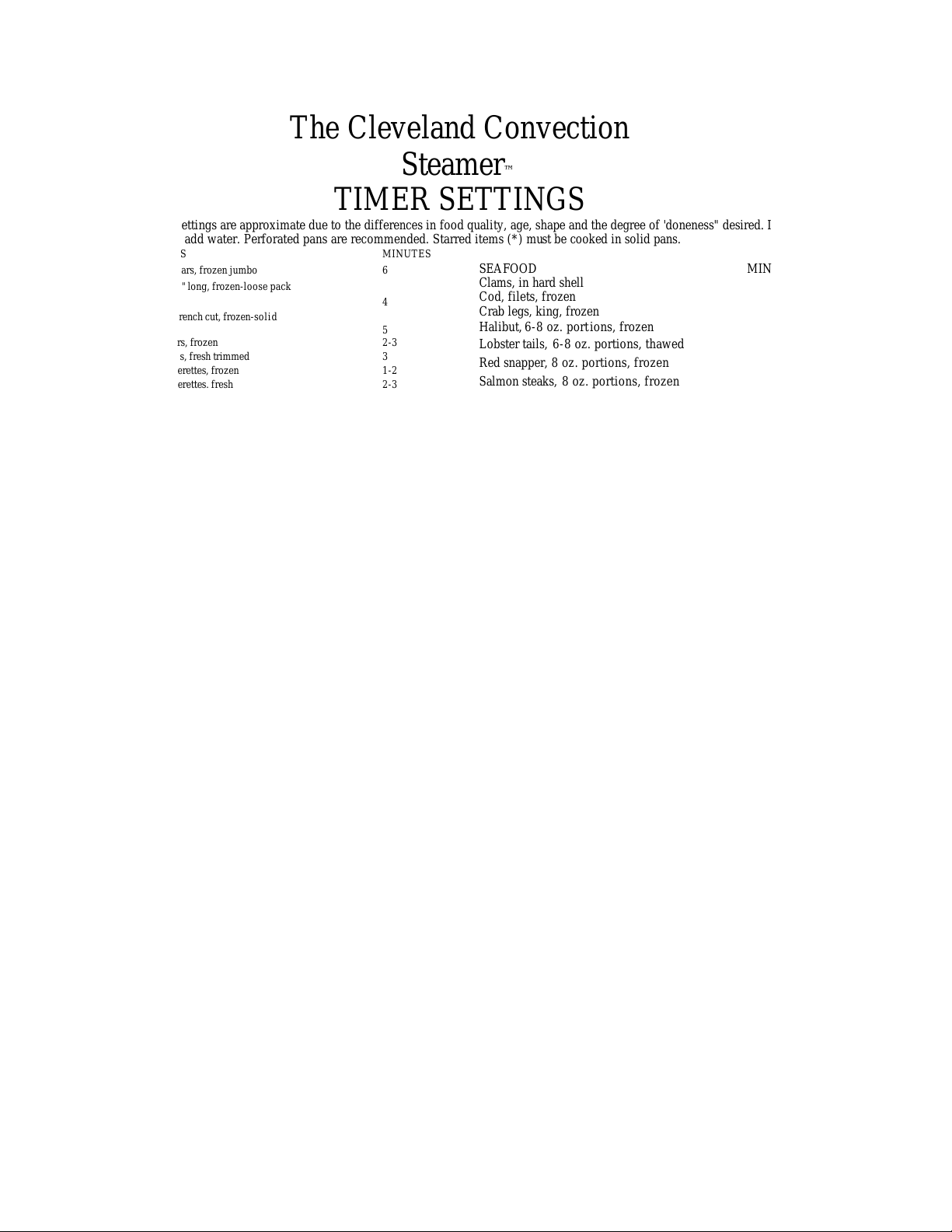
Steamer™
TIMER SETTINGS
Timer settings are approximate due to the differences in food quality, age, shape and the degree of 'doneness" desired. It is not
necessary to add water. Perforated pans are recommended. Starred items (*) must be cooked in solid pans.
VEGETABLES MINUTES
Asparagus, spears, frozen jumbo 6
Beans, green. 2" long, frozen-loose pack
Beans, green, french cut, frozen-solid
Broccoli, spears, frozen 2-3
Broccoli, spears, fresh trimmed 3
Broccoli, flowerettes. fresh 2-3
Cabbage, fresh, slices or wedges 2-4
Cabbage, fresh, 4-6 Ib. head for cabbage
rolls, steam, peel, repeat as necessary 2-4
Carrots, baby whole, fresh or frozen 10
Carrots, sliced or krinkle cut. frozen 3
Carrots, diced, frozen 2
Cauliflower, floweretts, fresh 4-5
Cauliflower, flowerettes. frozen 2-3
Celery, 1-1 1/2" diagonal cut
Celery, diced, for stuffing 2
Celery, minced
Corn, yellow wh. kernel, frozen-loose
pack 1
Corn on the cob, yellow, fresh 6
Corn on the cob, white, fresh 4
Corn on the cob, frozen 8-10
Eggplant. whole, fresh, to blanch 1
Mixed vegetables, frozen 2-3
Mushrooms, whole, fresh, 1/2" diameter 3
Onions, diced or sliced 2-3
Peas, green, frozen 2
Potato, sweet, whole 8 oz., with skin.
no foil 30-35
Spinach, leaf. fresh or thawed 1 1/2
Spinach, frozen 3 Ib. block 15-17
Squash acorn, cut into halves, no seeds 15
Squash, cooked, frozen 4 Ib. block 18-20
Zucchini, diced, fresh or frozen 2-4
FRUIT
Apples, cored, blanch for peeling 1
Apricots, dried 10
Grapefruit. blanch for peeling 1
Oranges, blanch for peeling 1
Peaches, blanch for peeling 1
Pineapple, whole, for cutting 1-2
Prunes, dried 10
DEHYDRATED FOODS
*Potatoes, random sliced, use 5 cups
cold water per Ib. 12
*Rice, long grain, use 4 cups cold water
per Ib. 17
3
1/
CLEVELAND RANGE, INC., 1333 EAST 179th ST., CLEVELAND, OHIO 44110
Manufacturer reserves right of design improvement or modification, as warranted.
Halibut, 6-8 oz. port ions, frozen 4-5
Lobster tails, 6-8 oz. portions, thawed 4-6
Red snapper, 8 oz. portions, frozen 4-5
Salmon steaks, 8 oz. portions, frozen 7
Shrimp, large, 10 count per Ib., frozen 4-6
MEATS
a timer setting.
6-8 Ib. cut with 1/2" water
Chicken. 8 oz. pieces, frozen 18-20
Meat loaf, fresh or frozen 5 min/lb
Weiners, frozen or thawed 2
PASTA
Lasagna noodles 12
Spaghetti, regular 10
PREPARED ENTREES
full size pan, 4" sq. servings 25-30
EGGS
Page 6
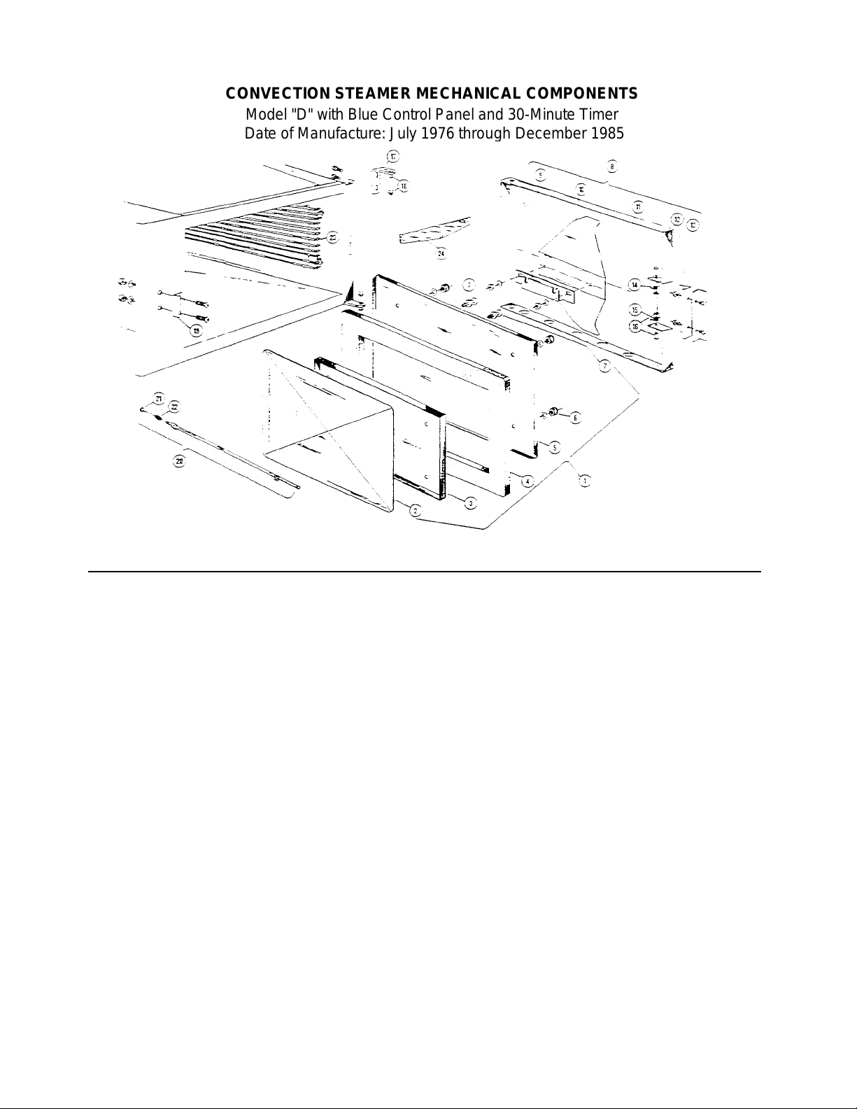
CONVECTION STEAMER MECHANICAL COMPONENTS
REFERENCE NUMBER
PART NUMBER
DESCRIPTION
1 42063
Inner Door Assembly
2 44098
Gasket Retainer Plate
3
66556
Inner Gasket Retainer Plate
4
07138
Gasket
5
04171
Inner Door
6
14667
1/4-20 Knurled Finger Nut
(4
required)
7
19923
Inner Door Mounting Stud
(2
required)
8
40818
* Outer Door Assembly
9
52488
Outer Door Mounting Bracket
10
69635
Door Spring
11 44057
Outer Door Weldment
12
40746
Door Latch
13
58177
Door Handle
14
19577
Upper Door Spring
15
19578
Lower Door Spring
16
40817
Latch Pin
&
Retainer
(2
required)
17
02414
Hinge Bracket (upper or lower)
18
40816
Hinge Pin
&
Retainer
(2
required)
19
53061
Door Catch
20
40299
Steam Tube Assembly
21
15201
Tube
"0"
Ring 22 19574
Tube Spring
23
41423
Slide Rack
24
40417
Drain Cover Screen
Model "D" with Blue Control Panel and 30-Minute Timer
Date of Manufacture: July 1976 through December 1985
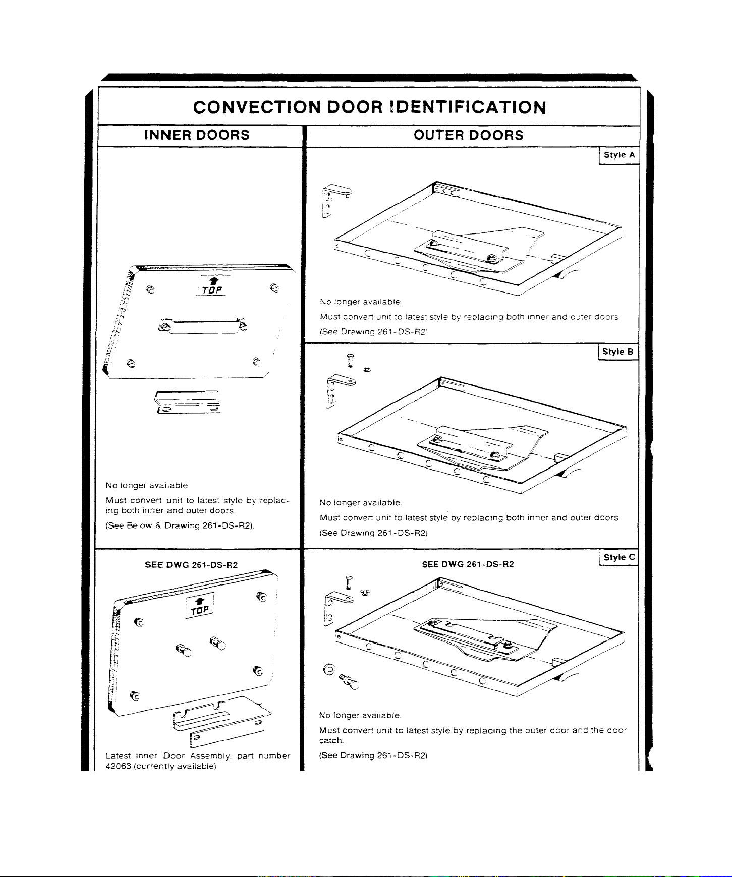
*Also available as part number 44056—
Replacement Outer Door Assembly with Latch and Handle, less Door Spring and Mounting Bracket. (Door latch # 08116 is no longer available. If
this door latch breaks, the entire outer door must be replaced with #44055, using the door spring and mounting bracket from the original door. In
addition, the door catch must be replaced with the replacement catch #53061, using the screws, nuts, and lockwashers from the original door catch.)
LITHO IN U.S.A.
CLEVELAND RANGE, INC., 1333 EAST 179th ST., CLEVELAND, OHIO 44110
Manufacturer reserves right of design improvement or modification, as warranted. 1286
Page 7
1283 LITHO IN U.S.A Manufacturer reserves right of design improvement or modification, as warranted
CLEVELAND RANGE, INC., 1333 EAST 179th ST., CLEVELAND, OHIO 44110
Page 8
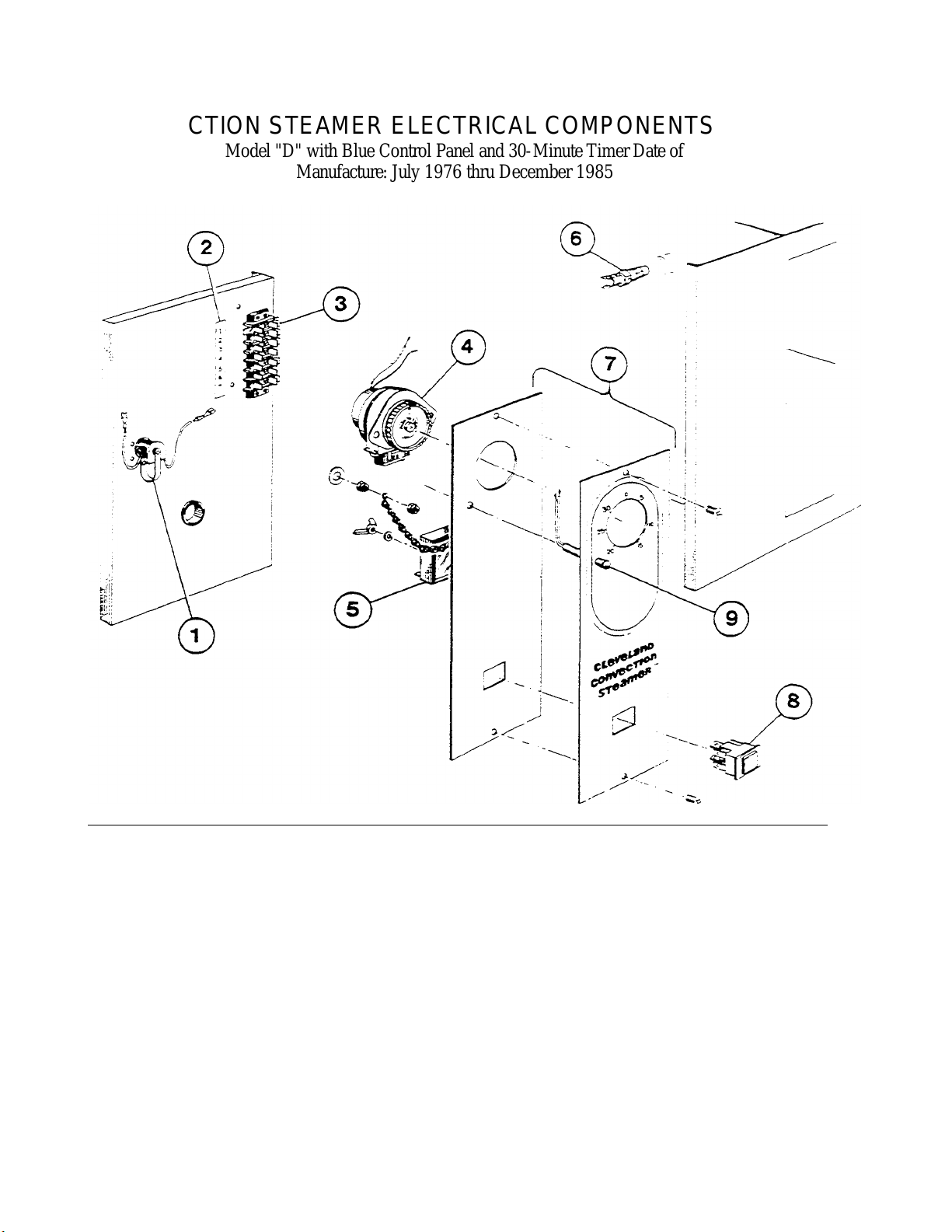
CONVECTION STEAMER ELECTRICAL COMPONENTS
Model "D" with Blue Control Panel and 30-Minute Timer Date of
Manufacture: July 1976 thru December 1985
REFERENCE NUMBER PART NUMBER DESCRIPTION
1 41350 Buzzer
2 14860 Terminal Block Label
3 02195 Terminal Block
4 43904 Timer
19996 Micro-Switch (2 required)
5 20477 Timer, Solid State
6 19972 Thermal Switch
7 100635 Instrument Panel
8 19978 Illuminated Push Button Switch (Timer By -Pass)
9 12159 Neon Indicator Light
10 19285 Instrument Panel Screw
CLEVELAND RANGE CO., 1333 EAST 179th ST., CLEVELAND, OHIO 44110
Manufacturer reserves right of design improvement or modification, as warranted.
LITHO IN U.S.A.
Page 9
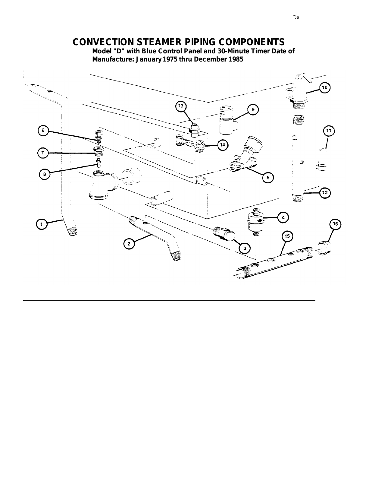
CONVECTION STEAMER PIPING COMPONENTS
1 63172
Drain Pipe, Upper Compartment Only
Model "D" with Blue Control Panel and 30-Minute Timer Date of
Manufacture: January 1975 thru December 1985
Data Sheet 261-DU (R3)
REFERENCE NUMBER DESCRIPTION
2 63171 Drain Pipe, Lower Compartment Only
3 22202* Safety Relief Valve — NO LONGER REQUIRED - NOT AVAILABLE
4 20559 Thermostatic Trap — Compact
5 22201 3/8" Solenoid Valve — Steam
6 06216 1/4" Tube x 1/4" Pipe Connector
7 02549 Condenser Bushing
8 14498 Nozzle — Steam Condenser (K-5)
9 22215 1/4" Solenoid Valve — Water
10 22131 3/4" Safety Valve — 15 psi
11 22140 Air Vent — NOT REQUIRED ON DIRECT CONNECT UNITS
12 63170 Steam Manifold
13 15455 Row Controller (regulator), 0.5 gpm
14 22099** Needle Valve
15 63162 Drain Manifold
16 03058 1-1/2" Cap
*Used until November 1982, then deleted from the steamer. **Optional
after November 4, 1982.
CLEVELAND RANGE CO., 1333 EAST 179th ST., CLEVELAND, OHIO 44110
Manufacturer reserves right of design improvement or modification, as warranted.
1086 LITHO IN U.S.A.
Page 10
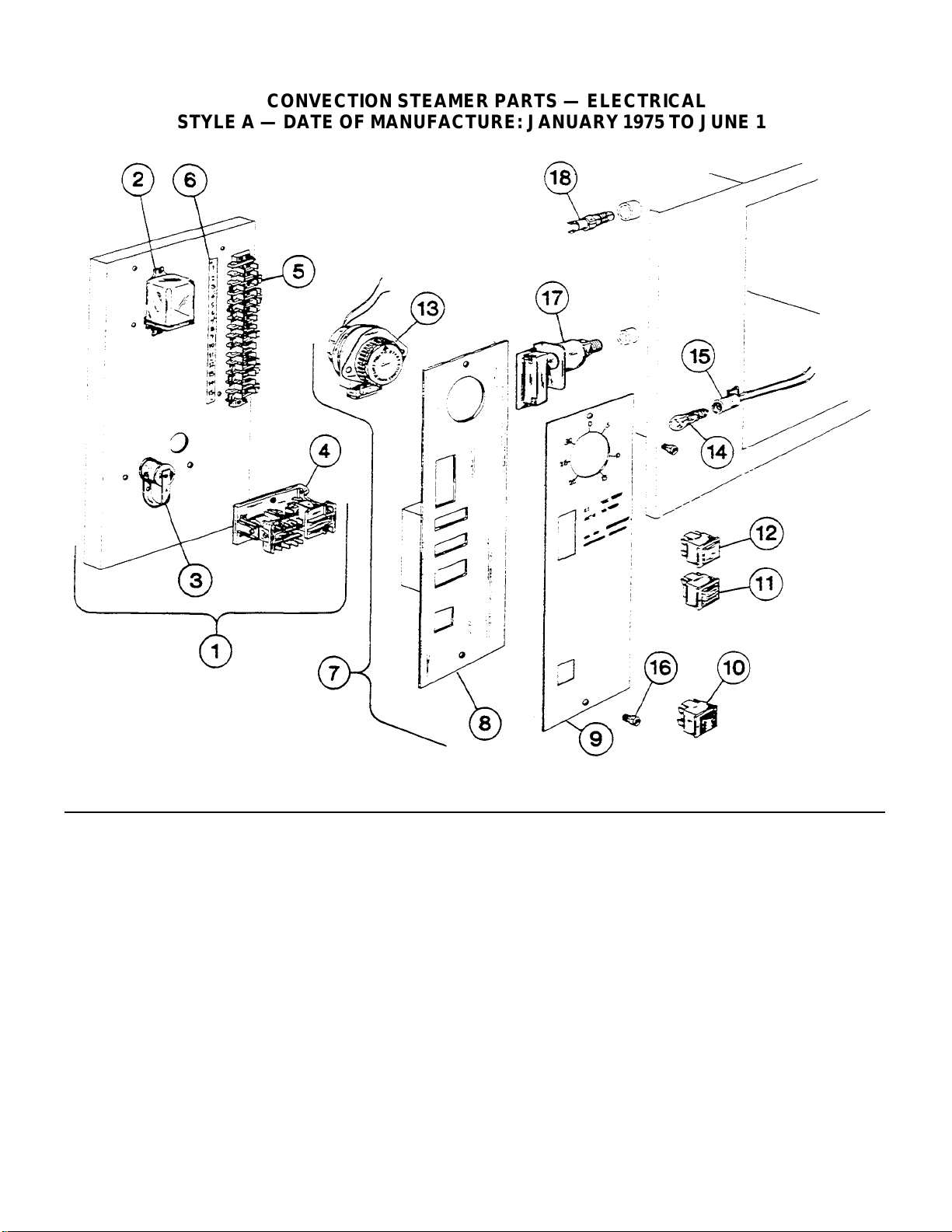
CONVECTION STEAMER PARTS — ELECTRICAL
1 47007
Divider Panel Electrical Assembly
2
03511
Relay, By
-
Pass 3 41350
Buzzer
4
03510
Rel
ay, Safety Circuit
5
02195
Terminal Block
- 7
Pole
(2
required)
6
14860
Terminal Block Label
7
47006
Instrument Panel Assembly (Not Available)
8
42236
Instrument Panel Sub
-
Assembly (Not Available)
9
14858
Instrument Panel Label (Not Available)
10
19975
Switch Illuminated Push Button (Red,
3
Terminal)
11
19974
Switch Illuminated Push Button (Amber,
3
Terminal)
12
19973
Switch Illuminated Push Button (White,
4
Terminal)
13
43904
Timer Assembly
14
02482
Bulb, 3W
-
120V 15 41351
Bulb Socket
16
19285
Instrument Panel Screw
17
19971
Pressure Switch
18
19972
Thermal Switch
REFERENCE
PART
DESCRIPTION
STYLE A — DATE OF MANUFACTURE: JANUARY 1975 TO JUNE 1975
Data Sheet 261-DT
NUMBER
NUMBER
CLEVELAND RANGE, INC., 1333 EAST 179th ST., CLEVELAND, OHIO 44110
Manufacturer reserves right of design improvement or modification, as warranted.
LITHO IN U.S.A.
Page 11
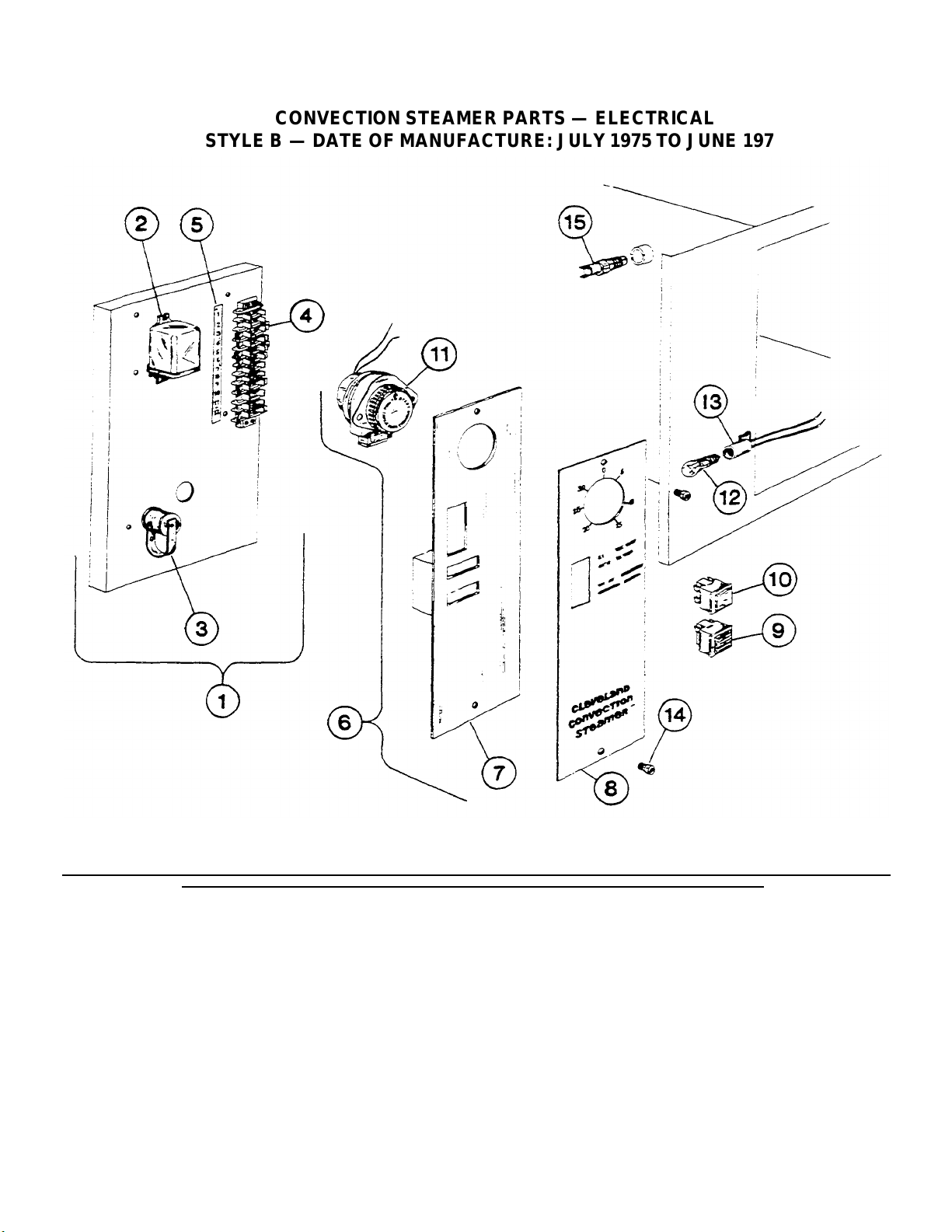
CONVECTION STEAMER PARTS — ELECTRICAL
2 03511
Relay, By
-
Pass 3 41350
Buzzer
5 14860
Terminal Block Label
6
47006
Instrument Panel Assembly (Not Available)
7
42236
Instrument Panel Sub
-
Assembly (Not Available)
8
14858
Instrument Panel Label (Not Available)
9
19974
Switch Illuminated Push Button (Amber,
3
Terminal)
10
19973
Switch Illuminated Push Button (White,
4
Terminal)
11
43904
Timer Assembly
12
02482
Bulb, 3W
-
120V 13 41351
Bulb Socket
14
19285
Instrument Panel Screw
15
19972
Thermal Switch
REFERENCE
PART
DESCRIPTION
STYLE B — DATE OF MANUFACTURE: JULY 1975 TO JUNE 1976
NUMBER
1 47007 Divider Panel Electrical Assembly
4 02195 Terminal Block - 7 Pole (2 required)
Manufacturer reserves right of design improvement or modification, as warranted. LITHO IN U.S.A.
NUMBER
CLEVELAND RANGE, INC., 1333 EAST 179th ST., CLEVELAND, OHIO 44110
Page 12

MODEL "D" CONVECTION STEAMER — (Since 7/76)
WIRING
DIAGRAM
COOKING COMPARTMENTS ELECTRICAL OPERATING SEQUENCE
TIMER CONTROL (Follows Operating
Instructions)
1. Timer's outer dial pointer is set to desired time
2. Disc in center of t imer is depressed:
a. Timer switches No. 1 and No. 2: normally open
contacts are closed and normally closed contacts
open.
b. Red indicator light comes on.
c. Steam solenoid and water solenoid valves open.
d. Steam activates the thermostatic switch (between
terminals 5 and 6 on the terminal block), starting
timer motor.
3. When the timer runs down to zero:
a. Timer switches No. 1 and No- 2: normally closed
contacts close and normally open contacts open.
b. Red in dicator light goes off.
c. Steam solenoid and water solenoid valves close.
d. Buzzer sounds for 3 seconds, then goes off.
MANUAL OPERATION
1. Red Manual (timer bypass) switch is depressed.
a. Switch lights up.
b. Steam solenoid and water solenoid valves open.
2. Unit will operate until the switch is depressed again,
SHEET 260-NP-1(R2)
NUMBERS CIRCLED ARE TRMINAL
BLOCK CONNECTIONS
causing its light to go off. ( No buzzer will sound).
3. The timer can be used during manual operation. It will "time-out"
and sound the buzzer, but it will not shut off the steam.
MODEL "D" CONVECTION STEAMER — (7/75-6/76)
COOKING COMPARTMENT'S ELECTRICAL OPERATING SEQUENCE
TIMER CONTROL (Follows Operating
Instructions)
1. Timer's outer dial pointer is set to desired time.
2. Disc in center of timer is depressed:
a. Timer switches No. 1 and No. 2: normally open contacts are
closed and normally closed contacts open.
3. "ON-OFF" switch is depressed, energizing circuit
a. "ON-OFF" switch lights up.
b. Back lighted yellow legend "COOKING' appears.
c. Steam solenoid and water solenoid valves open.
d. Steam activates and the thermostatic switch (be tween
terminals 7 and 8 on terminal block) starting
timer motor.
4. When the timer runs down to zero:
a. Timer switches No. 1 and No. 2: normally closed
contacts close and normally open contacts open.
b. Backlighted yellow legend "COOKING" disappears.
c. Steam solenoid and water solenoid valves close.
d. Buzzer sounds.
e. Backlighted green legend "COOKED" appears.
5. "ON-OFF" switch is depressed, deenergizing buzzer and circuit.
BYPASS CONTROL
1. "BYPASS" switch and "ON-OFF" switch are depressed:
a. "BYPASS" switch and "ON-OFF" switch light up.
b. Bypass relay is energized, closing contacts be tween terminals
7-5.
c. Backlighted yellow legend "COOKING" appears.
d. Steam solenoid and water solenoid valves open.
2. Unit will operate until the "BYPASS" switch and "ON-OFF"
switch are depressed again.
LITHO IN U.S.A. Manufacturer reserves right of design improvement or modification, as warranted.
CLEVELAND RANGE, INC., 1333 EAST 179th ST., CLEVELAND, OHIO 44110
Page 13

MODEL "D" CONVECTION STEAMER — (1/75-6/75)
WIRING DIAGRAM
COOKING COMPARTMENT'S ELECTRICAL OPERATING SEQUENCE
TIMER CONTROL
(Follows Operating Instructions)
1. Timer's outer dial pointer is set to desired time.
2. Disc in center of timer is depressed.
a. Timer switches No. 1 and No. 2: normally open contacts are
3. "ON-OFF" switch is depressed, energizing circuit
a. "ON-OFF" switch lights up.
b. Back lighted yellow legend "COOKING" appears.
c. Steam solenoid and water solenoid valves open.
d. Steam activates thermostatic switch (between terminals 7 and 8 on
4. When the timer runs down to zero:
5. "ON-OFF" switch is depressed, deenergizing buzzer and circuit
1. "BYPASS" switch and "ON-OFF" switch are depressed:
c. Backlighted yellow legend "COOKING" appears.
d. Steam solenoid and water solenoid valves open.
2. Unit will operate until the "BYPASS" switch and "ON-OFF" switch are
closed and normally closed contacts open.
terminal block) starting timer motor.
a. Timer switches No. 1 and No- 2: normally closed contacts close
and normally open contacts open.
b. Backlighted yellow legend "COOKING" disappears.
c. Steam solenoid and water solenoid valves close.
d. Buzzer sounds.
e. Backlighted green legend "COOKED" appears.
BYPASS CONTROL
a. "BYPASS" switch and "ON-OFF" switch light up.
b. Bypass relay is energized, closing contacts between
terminals 7-5.
depressed again.
SAFETY CIRCUIT
Assume unit in operation — either the timer control or the bypass control.
1. The cooking chamber is suddenly subjected to a pressure higher than
atmospheric:
a. Pressure switch (between terminal 15 of terminal
block and latch terminal A) is activated, energizing
latch relay.
b. Latch relay opens contact between terminals 1 and 7
and clo ses contact between terminals 6 and 9.
c. Power to the operating circuits is cut off.
d. The momentary switch lights up red.
e. Backlighted red legend "CLEAN-RESTART" appears.
2. When the condition that caused the over pressurization is corrected, push
the momentary switch in:
a. The backlighted red legend "CLEAN-RESTART" and
red illuminated switch will go off.
b. The release relay is energized closing contact between terminal 1 and
7 and opening contact between terminal 6 and 9.
3. The unit now returns to normal operations.
CLEVELAND RANGE, INC., 1333 EAST 179th ST., CLEVELAND, OHIO 44110
LITHO IN U.S.A.
Manufacturer reserves right of design improvement or modification, as warranted.
Page 14

MAINTENANCE INSTRUCTIONS FOR STEAM GENERATORS
Distribution of hard water in the U.S.
0-60
parts per million
(EXCEPT THOSE EQUIPPED WITH TWO PROBES)
WARNING: Steam under pressure may cause serious
injury and bodily harm when it is accidentaily or
carelessly released. Therefore, service of the steam
generator should only be performed by trained and
experienced personnel, thoroughly familiar with
servicing steam generators.
CAUTION: Never work or the steam generator when it
is hot or pressurized.
Every steam generator shipped is equipped with at least
one corrosion resistor (cathodic). The larger capacity
steam generators will have two corrosion resistors.
The hand hole plate and gasket on your steam generator
stops the escape of steam through the hand hole opening
during operation.
1) Turn off all energy sources to steam generator. Drain
steam generator.
2) Remove hand hole cover plate from steam generator.
3) Hang corrosion resistor from the right side of the front stay
rod, away from the probes. Clean scale and rust off a portion
of the stay rod, so the hanger will rest on the bright, bare
metal.
4) Reinstall the hand hole plate, along with a new gasket.
The hand hole plate should be cleaned and examined every
time it is removed. If the hand hole plate is chipped or
cracked, or over three years old, install a new one. Because
continuous use and possible abuse cause metal fatigue
which weakens the hand hole plate. a new one should be
installed at least every three years.
CAUTION: Never tighten the hand hole plate nut when
steam generator is In use, hot, or otherwise
pressurized. Never tighten nut over 15 foot-pound
torque. Overtightening may cause uneven stress
which may result in the weakening and possible
breakage of the plate.
is shown on map, right. Areas shown
in black have hardest water, while
relatively soft water is found in white
areas. Shaded area require
supplemental feed water treatment
to remove or to reduce the
hardness.
This map is a general representation
and exceptions do exist Consult a
local water treatment specialist for a
water sample test.
60-120 parts per million
120-180 parts per million
above 180 parts per million
Replace the gasket whenever the hand hole plate is
removed or replaced. Keep a spare gasket on hand at all
times.
Replace the gasket at least once a year, or sooner if it a
cracked, torn or hardened.
Leakage of water past the hand hole plate should not be
allowed to continue, as this will cause pitting of the metal in
contact with the gasket.
5) After re-installing the hand hole plate, close the steam
generator drain valve. Turn on energy sources.
6) Start up and operate steam generator long enough to
observe that it is operating property.
The corrosion resistor is sacrificial and must be replaced at
regular intervals just before it is entirely consumed.
Frequency of replacement can only be established by a
regular inspection for how much of the protector remains and
whether scaling or pitting has begun. Scaling indicates a very
hard water condition. Pitting indicates an excess acid
condition. In either case, more protectors or more frequent
replacement of them is necessary. The best way to reduce
servicing time and to assure long generator life, is to provide
feed water that is low in solids content and low in gas content. Water that is fit to drink can still be high in impurities
that are highly detrimental to a steam generator. Consult a
water treatment specialist in your area for recommendations
concerning steam generator teed water treatment. Under
average conditions, the corrosion resistor provides about six
months of service. An average condition would meet each of
the following tests:
1) Less than 8 hours of steam generation a day.
2) One generator blowdown every day.
3) M oderately hard water. Lass than 85 ppm.
4) Water containing less than 60 ppm Total Dissolved Solids.
LITHO IN U.S.A.
CLEVELAND RANGE CO., 1333 EAST 179th ST., CLEVELAND, OHIO 44110
Manufacturer reserves right of design improvement or modification, as warranted.
Page 15

STEAM GENERATOR (BOILER) IDENTIFICATION
SERVICE NOTE
The above drawings showing the
sight gauge location and method of
mounting are for assisting In determining the proper part number for
replacement generators. When ordering
please provide both the proper part number
and the equipment’s serial number.
CLEVELAND RANGE CO., 1333 EAST 179th ST., CLEVELAND, OHIO 44110
1090 LITHO IN U.S.A. Manufacturer reserves right of design improvement or modification, as warranted.
Page 16

Data Sheet—: 260-LC(R1)
START-UP MAINTENANCE PROCEDURES — STEAM GENERATOR
IMPORTANT: The instructions must be followed in
order to prevent premature failure of the steam
generator.
START-UP:
1) Open the cabinet base door and close the drain valve if
it is open. (Red handle lever marked "blowdown".)
2) Flip the toggle switch on front of the cabinet console to
"ON" (up position). The red console light should then glow
and water will automatically begin filling the generator.
3) When the water level in the sight gauge glass (on the
generator) reaches— approximately 2/3 full (after approx-
imately five minutes). Depress the "ON" reset button on
the console. This will energize the electric heater elements
or ignite the gas burner. If the sight gauge glass shows no
stabilized water level, i.e., the gauge glass is completely
empty or completely fitted, have the generator serviced.
4) In approximately ten minutes you will notice the steam
pressure gauge, on the console, register the steam
pressure contained inside the generator.
5) Cooking may now begin. Refer to "Cooking" and
"Operating Procedure" data sheets for specific instructions.
MAINTENANCE:
1) At the end of each day's operation, while the generator
is pressurized, flip the console toggle switch to the
"Blowdown" position, open the door in the cabinet base
and open the generator's drain valve, (red handle). This
"Blowdown" procedure drains the water out of the
generator and helps to prevent lime scale formation. When
the generator is empty, flip the console toggle switch to the
"OFF" position and dose the generator's drain valve. It is
recommended that the generator be refilled with water
after the "Blowdown" is performed This can be
accomplished by flipping the toggle switch to the "ON'"
position for a period of five minutes and then returning the
switch to the "OFF" position.
CAUTION: Service on the generator should only be
performed by a trained and experienced service
technician, thoroughly familiar with servicing steam
generators. No work should be done on the steam
generator while it to pressurized or hot. Be sure all
energy source are shut off before the tart of any
work.
2) Even though the "Blowdown" re performed faithfully each
day. It will still be necessary to periodically inspect the inside
of the generator. The generator's hand hole plate should be
removed at regular intervals, so that it and the inside can be
inspected. The hand hole plate should be cleaned and
examined each time it is removed. If the hand hole plate is
chipped or cracked, or over three years old. Install a new
one. Replace the corrosion resistor(s) if necessary, and
chemically descale the generator if it is coated with lime
scale. A new hand hole gasket should always be installed.
3) It will be necessary to periodically have scale accumulations removed from the inside of the steam generator. by a
qualified service technician. Generator descaling instructions
are provided on a separate data sheet. Failure to periodically
remove scale from the inside of the generator will result in
greatly reduced generator life.
4) Every steam generator is equipped with at least one
corrosion resistor to reduce generator shell corrosion and
scaling. This corrosion resistor is sacrificial and must be
replaced at regular intervals just before it is entirely
consumed. In areas where the water a very hard, the
feedwater must also be treated to remove the harmful
mineral content.
Refer to separate data sheets for corrosion resistor servicing
instructions. feedwater treatment information. and hand hole
plate servicing instructions.
5) Check the safety valve once a week while steam generator
is pressurized. Test by pulling safety valve extension wire.
Valve must open freely and snap closed when released. If it
does not or if it drips constantly, a new safety valve is
needed.
6) If the steam generator is to be left idle for three months or
more, it should be drained and dried out and the hand hole
plate left off.
7) Water level in the sight gauge normally should be about
2/3 full. This level is maintained automatically.
Refer to separate data sheet for either mechanical or water
fill servicing instructions.
8) If gas fired, the lighting instructions are on the AGA rating
plate. Pilot burner is lit through hole in panel at bottom of
steam generator. This panel should never be left off as this
will damage the controls. Burners will not light without water
in the steam generator.
1090 LITHO IN U.S.A.
CLEVELAND RANGE CO., 1333 EAST 179th ST.. CLEVELAND, OHIO 44110
Manufacturer reserves right at design improvements or modification, as warranted.
Page 17

WATER QUALITY REQUIREMENTS — STEAM
27 parts per million
13 parts per million
GENERATOR PROTECTION AND MAINTENANCE
A steam generator, or boiler, unlike other types of water-using
kitchen equipment distills the water in order to make steam.
Nearly all feed-water sources contain dissolved minerals in
varying degrees of concentration. As this water is boiled, pure
steam rises from it’s surface, upward to the cooking
compartment(s), leaving minerals behind that can become
harmful to the steam generator. If minerals are allowed to
accumulate inside the steam generator, they win solidify as a
scale. Then, malfunctioning will occur, and serious equipment
damage may result.
The use of good quality generator feed water is the
responsibility of the owner/user. The use of poor quality feed
water could void equipment warranties. The minimum
treatment required in most areas is water softening, although
local water conditions may require more intensive
pretreatment than simply a water softener.
Scale problems occur when feed water is high in hardness.
total dissolved solids, silica, and alkalinity. Water softening will
only reduce the water's hardness, which a the presence of
dissolved salts of magnesium and calcium. Water softening
will not affect the multitude of other minerals found in most
water supplies. Because generator scale is the result or the
precipitation of many minerals, the best property to control, for
generator feed water, is total dissolved solids, not just
hardness.
The recommended minimum water quality standards, whether
untreated or pre-treated, based upon 10 hours of use per day,
and a Daily Blowdown, are as follows:
Total Dissolved Solids Less than 60 parts per million
Total Alkalinity Less than
Silica Less than
PH Factor
Consult a local water treatment specialist for an on-thepremises water analysis and for recommendations concerning
steam generator teed water treatment (if required). In order to
remove or reduce harmful concentrations of minerals.
If the recommended water quality requirements are met
without supplemental treatment, or it treatment is applied,
resulting in feed water quality meeting the prescribed
standard, the steam generator will need to be blown down only
once each day. In addition, the inside of the generator requires
an inspection (for excessive lime accumulation and consumed
corrosion resistors) only once every sac months. Replace the
corrosion resistors) and chemically descale the generator as
required.
If a pre-treatment unit cannot be installed, and the
recommended water quality requirements are not met, the
following procedures should be followed, in order to achieve
maximum steam generator service life. The steam generator
should be blown down after each 6 hours of use. Have the
steam generator inspected, inside and outside, by a qualified
technician every 3 months. If the corrosion resistor(s) is totally
or nearly consumed, replace it. If the inside of the generator is
heavily coated with scale, have it chemically descaled by a
qualified service technician.
Greater
than
7.5
INSTRUCTIONS FOR CHEMICALLY
DESCALING STEAM GENERATORS
WARNING: Steam under pressure may cause serious
injury and bodily harm when it is accidentally or
carelessly released. Improper handling of acid could
cause serious, permanent injury. Therefore, service of
the steam generator should only be performed by
trained and experienced personnel, thoroughly
familiar with servicing generators.
There are a number of commercial descaling chemicals
available, produced by various manufacturers. Those utilizing
a sulfamic and base, which can be identified by it’s powdered
form, are safe and compatible with our food preparation
equipment. It is imperative that the acid used for descaling be
FDA approved for use in food preparation equipment.
Various manufacturers may include additional chemicals to
increase potency, and therefore, instructions for a specific
brand should be followed carefully. If instructions are not
provided with the deliming chemical you purchase, the
following general guidelines may be followed.
WARNING: Exercise care when handling acid. Avoid
contact with skin, eyes, or clothing. Wear safety glasses
or face shield, along with rubber gloves and rubber
apron. In case of exposure to clothing, remove clothing
and flush with water. In case of exposure to skin or eyes,
flush with water for 15 minutes and get immediate
medical attention. Do not take internally. Keep out of the
reach of children.
Be sure the generator has been drained, depressurized, and
is cool. Open the hand hole access on the front of the
generator and place approximately 8-10 pounds of sulfamic
acid inside the generator. Put a new hand hole gasket on the
hand hole plate, and replace the hand hole plate, tightening
the bar and nut assembly to a maximum of 15 foot pounds
torque. The generator must be completely filled with hot
water (fill the generator beyond its normal, automatic fill point
of 2/3 up in the sight gauge). On mechanical fill generators,
this can be accomplished by adding weight to the float or
removing the float and regulating the fill level with a hand
valve in the water supply plumbing. On electric fill generators
(with probes), this can be accomplished by temporarily
jumpering terminals #3 & #4 of the water control relay. Turn
the main on-off toggle switch to the "ON" position, than turn
the switch to the "OFF" position when the generator is
completely filled. Let the solution stand for several hours,
then flush with water. Rinse with a solution of bicarbonate of
soda of soda to neutralize any acid residue, and again, flush
with water.
CAUTION: Never tighten the hand hole plate nut when
the steam generator is in use, hot, or otherwise
pressurized. Never tighten nut over 15 foot pounds
torque. Overtightening may cause uneven stress,
which may result in the weakening and possible
breakage of the plate.
CLEVELAND RANGE CO., 1333 EAST 179th ST., CLEVELAND, OHIO 44110
Manufacturer reserves right of design improvement or modification, as warranted.
1090 LITHO IN U.S.A.
Page 18

PROBE SYSTEM: ELECTRIC WATER FILL AND
SERVICING
INSTRUCTIONS
ELECTRIC LOW WATER FUEL CUT OFF FOR STEAM
GENERATOR — 3 PROBE TYPE
WARNING: Service of the steam generator must be performed only
During operation of the steam generator, the water level is maintained automatically by unequal length probe extensions inside. The
probes and extensions must be kept clean and free of scale deposits in order to function properly.
The probe extensions are sensors in a control system which monitors and
maintains the water level between the end of the short probe extension
and the end of the intermediate extension.
by trained and experienced service technicians.
The long probe, called "Low Water," is a safety sensor which shuts off
the fuel supply if there is insufficient water in the steam generator.
Since the control system is all electric and these parts don't move or wear,
they can be expected to have a long life. If they do malfunction, it is generally because untreated hard feed water is being used in the
steam generator. This forms scale on the submerged ends of the probe extensions and on the top horizontal surfaces of the probes.
After this scale is removed, the parts will function property.
To eliminate the cause of scaling, refer to separate data sheets for feed water treatment information and corrosion protector servicing
instructions. Probes and probe extensions should be wiped clean each time the corrosion protector is replaced.
Erratic operation may result from loose connections on either end of the probe. The external end of the probe has a nut to hold the
wiring terminal snugly to the probe. This nut, if loose, may be tightened, firmly but gently. Too much torque will turn the center piece
of the probe and misalign the attached probe extension inside, causing the probe to become inoperative.
Inside the steam generator, the screw which holds the probe extension to the probe may be loose, allowing the probe extension to
swing or rest against some part of the steam generator. This can be corrected by removing the hand hole plate and reaching inside to
align and hold the probe extensions vertically while tightening the screws.
To Service the Probes or the Probe Extensions
1) Turn off all utilities and fuel to steam generator. Drain Steam generator.
CAUTION: Never work on the steam generator when it is hot or pressurized.
2) Remove probe cover on outside of steam generator to expose probe terminals. Examine for loose wiring terminals
3) Remove hand hole cover plate from steam generator. See separate data sheet for instructions.
4) Remove probe extensions from probes on inside of steam generator, clean off scale, and re-install. Or install new probe extensions
if preferred.
5) Remove scale from the probe (see sketch above). Do hot use an abrasive on the teflon insulator. If the old probe needs
replacement, install a new one.
(CONTINUED ON THE REVERSE SIDE)
CLEVELAND RANGE, INC., 1333 EAST 179th ST., CLEVELAND, OHIO 44110
Manufacturer reserves right of design improvement or modification, as warranted.
LITHO IN U.S A
Page 19

PROBE SYSTEM: ELECTRIC WATER PILL AND
SERVICING
INSTRUCTIONS
ELECTRIC LOW WATER FUEL CUT OFF FOR
STEAM GENERATOR — 3 PROBE TYPE
6) Assemble probe extensions to probes on inside of steam a generator so they hang an vertically, parallel to each
other. Malfunctioning will occur if an extension touches any part of the steam generator or another probe extension.
7 ) If insulation on electrical wires to the probe shows signs of being broken, cut, or deteriorated, the wires should be
replaced.
8) Connect wire terminals on outside of steam generator to probe terminals as follows:
Red wire to the shortest probe. Turns water off.
Black wire to the intermediate probe. Turns water on.
White wire to the longest probe. Shuts off fuel (low water safety fuel shut -off).
9) Re-install hand hole plate and install a new gasket.
The hand hole plate should be cleaned and examined each time it is removed. If the plate is chipped or cracked, it should
be replaced immediately. Because continuous use and possible abuse can cause metal fatigue, which weakens the hand
hole plate, a new one should be installed at least every three years. Replace the gasket at least once a year —or sooner if
it is cracked or hardened.
10) Replace probe cover and check to make sure that the cover does not contact probes.
11) Close steam generator drain valve. Turn on utilities and fuel supply to steam generator.
12) Operate and observe steam generator long enough to insure that it is functioning properly.
Low Water Fuel Cut Off Test
Proper operation of the "Low Water" probe extension should be checked periodically by someone who is thoroughly
familiar with the equipment.
To Test: Open the drain of the steam generator while fuel is on. When the water has drained below the "Low Water"
probe, the fuel should shut off automatically. Indication of fuel shut off should occur just as the water level in the sight
gauge drops from view. If it does, close the drain, allow the steam generator to refill, and resume normal operations. It the
fuel does not shut off, immediately turn the on-off toggle switch to the "off" position, and follow the steps outlined under "To
Service the Probes or the Probe Extensions" as given on the reverse side of this sheet.
For specific information pertaining to the operation of the electric water fill controls, and electric low water safety fuel cut off, refer to the following data sheets:
Electric Steam Generators
Gas-Fired Steam Generators
Steam Coil (electric operated) Generators
1086
CLEVELAND RANGE, INC., 1333 EAST 179th ST., CLEVELAND, OHIO 44110
Manufacturer reserves right of design improvement or modification, as warranted.
Page 20

STANDING PILOT-IGNITION TYPE GAS CONTROLS
To adjust the pilot flame:
3;
WARNING: Be sure to replace cover screw
after adjustment
FOR GAS-FIRED STEAM GENERATORS
CAUTION: The following procedures, as well as other work on the gas controls, should be performed only by a trained and
experienced service technician, thoroughly familiar with gas controls.
Built in gas controls assure safe and automatic operation of the pilot and main burners of the steam generator.
The control's consist of a pilot generator (thermocouple) and a unit called the combination gas control. This latter unit consists of a gas valve operator
and servo gas pressure regulator.
Generally, there is no need to make an adjustment to any portion of the gas system. The main burner orifices and the pilot burner orifice installed at the
factory are correct for the kind of gas specified on the purchase order. Also, the primary air supply to the main burner is properly adjusted for complete
combustion.
Lighting and Shutdown Instructions
Flip electrical switch on. Open water valve. Open gas valve. Slightly depress and turn control knob to "off" for 5 minutes before lighting gas. Turn
control knob to "pilot,” depress it completely, and light pilot burner. Continue to hold knob in for about 60 seconds, then release. Pilot burner is lighted
through hole in panel at bottom of steam generator. Never leave panel off. As this will damage controls. Turn control knob to "on". Depress electrical
switch for main burner ignition. Burners will not light without
water in the steam generator. For main burner off, with pilot on.
turn control knob to "pilot". For main and pilot burner off,
slightly depress and turn control knob to "off". Flip electrical
switch off.
Occasionally, due to regional differences in the gas supply, the
pilot burner flame may require adjustment.
A normal flame is mostly blue and steady, and envelops 3/8” to
½”of the tip of the pilot generator, as illustrated at right.
The pilot gas adjusting screw can be found under a cover screw
located near the gas control knob. illustrated below.
1) Remove the pilot adjustment cover screw.
to prevent possible gas leakage.
Electrical connections in the pilot generator circuit must se clean and secure.
Because the pilot generator operates in a severe environment, it may eventually need a replacement. The time before replacement will vary from one piece
of equipment to another, depending on the amount of usage. The pilot generator (thermocouple) should generate 450-750 MV in an open circuit condition.
When a malfunction is traceable to the combination gas control unit, it is recommended that the entire unit be replaced with a new one, rather than
attempting repairs to the old unit.
WARNING: To prevent the danger of possible gas leakage, the installer must be a trained and experienced service technician, thoroughly familiar
with gas controls.
1053
LITHO IN U.S.A. Manufacturer reserves right of design improvement or modification, as warranted.
CLEVELAND RANGE, INC., 1333 EAST 179th ST., CLEVELAND. OHIO 44110
Page 21

HOW THE ELECTRIC (WARRICK RELAY)
GAS BOILER CONTROL CIRCUIT
WATER LEVEL CONTROLS OPERATE — ON
GAS FIRED STEAM GENERATORS (WITH 3
PROBES)
Inside Cleveland Range Co. boilers which have electric water
level controls, there are three probe extensions vertically
oriented above the water with their lower ends positioned at
various levels.
Water is admitted to the boiler and is shut off in response to
the water level sensed by the tips of the short and the medium
length probe extensions. The electrical conductance of the
water is used in this system for controlling its level.
The third probe extension is a low water safety cutout sensor
and operates on the same principle.
Operation Sequence — Water Level Control
Assume an empty boiler. To fill, close Switch S for the
following operations:
1) Solenoid SV2 is energized allowing the boiler to fill with
water at the same time the primary circuit of Transformer T1 is
also energized.
2) The boiler will continue to fill until the water level reaches
the Water Off probe extension completing the T1 secondary
circuit, and energizing Relay Coil RC1
3) When Relay Coil RC1 is energized the normally closed
contact opens, de-energizing Solenoid SV2 stopping the water
fill. The normally open contact is closed, completing the circuit
to the Water On probe.
When the water boils away below the end of the Water On
probe extension the following occurs:
1) The secondary circuit of Transformer T1 is broken and the
Relay Coil RC1 is de-energized.
2) When Relay Coil RC1 is de-energized the normally open
contact opens, breaking the circuit to the Water Off probe
extension. And. the normally closed contact closes, energizing
Solenoid SV2 allowing the boiler to fill as in Step 2 above.
Data Sheet 260-NA
Operation — Low Water Safety Cutout
When Switch S is closed the following operations occur:
1) The primary circuit of Transformer T1 is energized.
2) When the water level reaches the low water safety cutout
probe extension and the momentary reset switch is manually
closed. Relay Coil RC2 is energized.
3) When Relay Coil RC2 is energized the normally open
contacts close, completing the low water safety circuit through
Contacts 7 and 8 and completing the circuit through Contacts
3 and 4, completing the 750 millivolt pilot generator circuit and
allowing the gas control package valve to operate.
If the water level drops below the Low Water Safety Cutout
probe extension, the following occurs:
1) The secondary circuit of Transformer T2 is broken and the
Relay Coil RC2 is de-energized. Contacts 7 and 8 and 3 and 4
open, breaking the 750 millivolt circuit
CLEVELAND RANGE CO., 1333 EAST 179th ST., CLEVELAND, OHIO 44110
Manufacturer reserves right of design improvement or modification, as warranted.
0482 LITHO IN U.S.A.
which shuts off the flow of gas to the burners.
The burners will not operate until water level in the boiler is
normal and the reset switch is operated.
Operation-Boiler Drain Condenser
To activate the Boiler Drain Condenser System close switch S
by placing toggle in the down position.
To drain boiler, open boiler drain ball valve. The heat from the
boiler drain water will close the normally open thermal switch
TS and energize the condenser solenoid valve SV3. To de-
activate the Boiler Drain Condenser System open switch S by
moving toggle to center off position.
Page 22

HOW THE ELECTRIC (WARRICK RELAY)
ELECTRIC BOILER CONTROL CIRCUIT
WATER LEVEL CONTROLS OPERATE —
ON ELECTRIC STEAM GENERATORS
(WITH 3 PROBES)
Inside Cleveland Range Co. boilers which have electric water level
controls, there are three probe extensions vertically oriented above the
water with their lower ends positioned at various levels.
Water is admitted to the boiler and is shut off in response to the water
level sensed by the tips of the short and the medium length probe
extensions. T he electrical conductance of the water is used in this sys-
tem for controlling its level.
The third probe extension is a low water safety cutout sensor and
operates on the same principle.
Operation Sequence — Water Level Control
Assume an empty boiler. To fill, close Switch S for the following
operations:
1) Solenoid SV2 is energized allowing the boiler to till with water at
the same time the primary circuit of Transformer T1 is also energized.
2) The boiler will continue to fill until the water level reaches the
Water Off probe extension completing the T 1. secondary circuit, and
energizing Relay Coil RC1.
3) When Relay Coil RC1 is energized the normally closed contact
opens, de -energizing Solenoid SV2 stopping the water fill. The
normally open contact is closed, completing the circuit to the Water
On probe.
When the wat er boils away below the end of the Water On probe
extension the following occurs:
1) The secondary Circuit of Transformer T 1 is broken and the Relay
Coil RC1 is de -energized.
2) When Relay Coil RC1 is de -energized the normally open contact
opens, breaking the circuit to the Water Off probe extension. And, the
normally closed contact closes, energizing Solenoid SV2 allowing the
boiler to fill as in Step 2 above.
Operation — Low Water Safety Cutout
When Switch S is closed the following operations occur
1) The primary circuit of Transformer T 2 is energized.
2) When the water level reaches the low water safety cutout probe
extension and the momentary reset switch is manually closed. Relay
Coil RC2 is energized.
3) When Relay Coil RC2 is energized the normally open contacts
close, completing the low water safety circuit through Contacts 7 and
8, and completing the circuit through Contacts 3 and 4, energizing
Contactor Coil C1 which closes the heater circuit.
If the water level drops below the Low Water Safety Cutout probe
extension, the following occurs:
1) The secondary circuit of Transformer T 2 is broken and the Relay
Coil RC2 is de -energized. Contacts 7 and 8 and 3 and 4 open, breaking
the circuits to Contactor C1 thereby turning off the heaters.
CLEVELAND RANGE CO., 1333 EAST 179th ST., CLEVELAND, OHIO 44110
Manufacturer reserves right of design improvement or modification, as warranted. 0482
LITHO IN U.S.A.
Data Sheet 260-MZ
The Contactor C1 will not operate until water level in the boiler is
normal and the reset switch is operated.
Operation-Boiler Drain Condenser
To activate the Boiler Drain Condenser System ,close switch S by
placing toggle in the down position.
To drain boiler, open bo iler drain ball valve. The heat from the boiler
drain water will close the normally open thermal switch TS and
energize the condenser solenoid valve SV3. To de -activate the Boiler
Drain Condenser System open switch S by moving toggle to center
off position.
Page 23

ELECTRIC STEAM GENERATOR (BOILER) ASSEMBLY
— 3
PROBE TYPE 24KW, 36KW,
&
48KW (2, 3, & 4 HEATER ELEMENTS) — 1968 to PRESENT
CLEVELAND RANGE CO., 1333 EAST 179th ST., CLEVELAND, OHIO 44110
Manufacturer reserves right of design improvement or modification, as warranted.
LITHO IN U.S.A. 0388
Page 24

ELECTRIC STEAM GENERATOR (BOILER) ASSEMBLY — 3 PROBE TYPE
1
43936 Boiler shell only, with legs. hand hole plate assembly, mounting studs for
3"
sq
uare-flanged
1/4"
ball valve water supply shutoff.
1/2" water feed solenoid valve.
Signal light,
115/220
v
olt. 1/2
"
(Pressure Steamers only).
1/4" solenoid valve
— boiler condenser water supply
24KW, 36KW, & 48KW (2, 3, & 4 HEATER ELEMENTS) — 1968 to PRESENT
REFERENCE
NUMBER
2 43895 Corrosion resistor, with hanger.
3 40445 Water gauge set with glass.
4 07302 Glass only 6" long.
5 40462 Probe with lock washer and screw.
6 101467 Probe extension set (3).
7 40421 Hand hole plate ass'y., including bar, nut, and gasket.
8 07106 Hand hole gasket, flat. 4" x 6" oval
9 08165 Electric immersion heater, with gasket. 3" flange. 12KW. 208/220 volt, 3 phase.
10 07128 Heater gasket — 3" square.
11 53250 Probe cover.
12
13 03514 Low water cut-off relay, 115 volt, (1C1DO).
14 03276
15 22102 1/4" check valve.
16 44095
17 19870 1/4" line strainer.
18
19 20533 Transformer, 75VA, (All, except Convection Steamers).
20 02193 Heavy duty terminal block — use with more than one contactor (125 amp size).
20A 02196 Heavy duty terminal block — use with more than one contactor (250 amp size).
21 20535 Transformer. 150VA, (Convection Steamers only).
22 03202 Circuit breaker for 20535.
23 19947 Pressure switch (Models after 1-70)
24 22130 Safety valve — 8 psi
25 19968 Reset switch.
26
27 12161 Signal light, 115/220 volt, 1"
28 07173 Steam pressure gauge, rear mount. 0-30 psi. 2 1/2"
29 03277 Generator drain valve — ball type
30 22140 Air vent.
31 40471 Control enclosure.
32 52568 Cover, control enclosure.
33 22122 3/4" pressure reducing valve, 3-15 psi output (optional).
34 19945 Float switch with gasket — low water cut off (California only).
35 22104
36 19979 Thermal switch — boiler condenser.
37
PART
NUMBER
43938
07108 Fibre washer (2 required)
23132 Gauge glass washer (2 required).
43748 Hand hole plate only.
08166 Electric immersion heater, with gasket. 3" flange, 12KW. 230/240 volt, 3 phase.
08167 Electric immersion heater, with gasket 3" flange, 12KW. 440/480 volt. 3 phase.
08214 Electric immersion heater, with gasket 3" flange. 12KW. 208/220 volt. 1 phase.
08215 Electric immersion heater, with gasket 3" flange. 12KW. 230/240 volt, 1 phase.
08216 Electric immersion healer, with gasket. 3" flange, 12KW. 440/480 volt, 1 phase.
08175 Electric immersion heater, with gasket. 2 1/2" flange, 12KW. 208/220 volt. 3 phase
08176 Electric immersion heater, with gasket 2 1/2" flange, 12KW. 230/240 volt. 3 phase.
08177 Electric immersion heater, with gasket. 2 1/2" flange, 12KW. 440/480 volt. 3 phase
07115 Heater gasket — 2 1/2" square.
03504
03509
03506 Contactor — 75 amp.
22131 Safety valve — 15 psi
19944
19967 On-Off power switch. 115 volt 3PDT (after 1-78) and all auto blowdown.
12169
07168 Steam pressure gauge, rear mount. 0-30 psi, 2" (Pressure Steamers only)
22106
DESCRIPTION
heater elements.
Boiler shell (43937) above. also including two corrosion resistors, sight gauge, three probes and
extensions with cover box.
Water control relay, 115 volt (1D1DO).
Contactor — 50 amp.
24KW, 220 volt, single phase and 48KW, 208. 220 & 240 volt. three phase
On-Off power switch. 115/220 volt DPST (before 1-78).
Valve, solenoid. 1/2" boiler auto blowdown, 115 volt (optional)
CLEVELAND RANGE CO., 1333 EAST 179th ST., CLEVELAND, OHIO 44110
Manufacturer reserves right of design improvement or modification, as wa rranted. LITHO IN
U.S.A. 0388
Page 25

WIRING DIAGRAM
WIRING DIAGRAM FOR ELECTRIC STEAM GENERATORS
COLOR CODE
WIRING DIAGRAM FOR ELECTRIC STEAM GENERATORS
COLOR CODE
ELECTRIC STEAM GENERATORS
WITH ELECTRICAL LOW-WATER HEATER CUTOFF,
WITHOUT MANUAL SAFETY RESET CIRCUIT
We are aware of the poor quality and are making
arrangements with the Manufacturer for a better copy.
PRIOR TO JANUARY, 1978
WITH ELECTRICAL LOW-WATER HEATER CUTOFF,
WITH MANUAL SAFETY RESET CIRCUIT
AFTER JANUARY, 1978
BK - BLACK G - GREEN
BL - •BLUE R - RED
BR - BROWN W - WHITE
PU - PURPLE Y - YELLOW
W - WHITE BR - BROWN
R - RED BL - BLUE
Y - YELLOW
G - GREEN
BK •BLACK
CLEVELAND RANGE CO.. 1333 EAST 179th ST.. CLEVELAND. OHIO 44110
0882 LITHO IN U.S A Manufacturer reserves right of design improvement or modification As warranted.
Page 26

Data Sheet— 200-EA-2
0882 LITHO IN U.S.A.
CLEVELAND RANGE CO., 1333 EAST 179th ST., CLEVELAND, OHIO 44110
Manufacturer reserves right of design improvement or modification, as warranted.
Page 27

GAS STEAM GENERATOR (BOILER) ASSEMBLY
— 3
PROBE TYPE
160,000 BTU (3 BURNER) & 200,000 BTU (4 BURNER)
CLEVELAND RANGE CO., 1333 EAST 179th ST., CLEVELAND, OHIO 44110
0985 LITHO IN U.S.A.. Manufacturer reserves right of design improvement or mo dification, as warranted.
Page 28

REFERENCE
1 43872 Boiler shell only. with legs. studs, hand hole plate assembly, and top flue bracket
NUMBER
GAS STEAM GENERATOR (BOILER) ASSEMBLY — 3 PROBE TYPE
160,000 BTU (3 BURNER) & 200,000 BTU (4 BURNER)
PART
NUMBER
DESCRIPTION
40298 Boiler shell 43872 above, also including two corrosion resistors, sight gauge, insulation panels, top flue
2 40421 Hand hole plate assembly, including bar. nut and gasket
2A 43748 Hand hole plate only.
3 07106 Hand hole gasket flat 4x6 oval.
4 43941 Left side insulating panel assembly.
5 43943 Right side insulating panel assembly
6 56320 Top flue collector-
8 42360
9 40462 Probe with lock washer and screw.
10 40455 Probe extension set (3).
11 52350 Probe cover.
12 43895 Corrosion resistor.
13
14 07302 Glass only — 6" long.
15 43851 3-burner front baffle assembly — Natural Gas.
16 43852 4-burner front baffle assembly — Natural Gas.
17 41365 3-burner rear burner support (after 7-76).
18 41366 4-burner rear burner support (after 7-76).
19 19870
20 44095
21 22102
22 03276
23 03277 Generator drain valve — ball type.
24 02499 Main gas burner.
25 15453 Main burner orifice — Natural Gas.
26 40901 Gas manifold assembly — 3 burner (after 7-76).
27 40902 Gas manifold assembly — 4 burner (after 7-76).
28 19632 Orifice holder (after 7-76).
29 43651 Pilot generator assembly with 02505 burner. 20410 thermocouple. 52449 bracket and 15460 orifice.
30 20410 Pilot thermocouple.
31 02505 Pilot burner — Natural Gas.
32 52449 Pilot bracket
33 15460 Pilot burner orifice — Natural Gas.
34 22182
34A 22096
35 22122
36 22130 Safety valve — 8 psi.
37 22140 Air vent
38 19947 Pressure switch.
39 03514 Low water cut -off relay. 115 volt, (1 C1DO).
40 03504 Water control relay. 115 volt, (1 D1 DO).
41 07173 Steam pressure gauge, rear mount, 0-30 psi.
42 19967 On-Off power switch, 115/220 volt, 3 PDT.
43 19968 Reset switch.
44 12161 Signal light 115/220 volt
45 19945 Float switch with gasket — low water cut-off (California only)
46 22104
47 19979 Thermal switch — boiler condenser.
48 22106
49 05263
40115 Top insulation baffle assembly (flat).
40116 Top ins ulation baffle assembly (with flange)
40445
07108 Fibre washer (2 required).
23132 Gauge glass washer (2 required).
43855 3-burner front baffle assembly — LP. Gas.
43856 4-burner front baffle assembly — L.P. Gas.
69952 3-burner rear burner support (before 7-76).
69953 4-burner rear burner support (before 7-76).
15450 Main burner orifice — L.P. Gas.
40905 Gas manifold assembly — 3 burner (before 7-76).
40906 Gas manifold assembly — 4 burner (before 7-76).
19631 Orifice holder (before 7-76).
43653 Pilot generator assembly with 02523 burner. 20410 thermocouple. 52449 bracket and 15461 orifice.
02523 Pilot burner — L.P- Gas -
15461 Pilot burner orifice — L.P. Gas.
22131 Safety valve — 15 psi.
collector with insulation and cover plate, three probes and extensions with cover box.
Internal flue riser assembly.
Water gauge set with glass.
1/4" line strainer.
1/2" water feed solenoid valve.
1/4" check valve.
1/4" ball valve — water supply shut -off.
1/2" combination gas control valve — Natural Gas.
1/2" combination gas control valve — L.P. Gas.
3/4" pressure reducing valve. 3-15 psi output (optional).
1/4" solenoid valve — boiler condenser water supply.
Valve, solenoid, 1/2" boiler auto blowdown, 115 volt (optional).
Radiator Ell 3/4" union.
CLEVELAND RANGE CO., 1333 EAST 179th ST., CLEVELAND, OHIO 44110
0985 LITHO IN U.S.A. Manufacturer reserves right of design improvement or modification, as warranted.
Page 29

GAS STEAM GENERATOR (BOILER) ASSEMBLY
— 3
PROBE TYPE
250.000 BTU (5 BURNERS) ft 300,000 BTU (6 BURNERS)
CLEVELAND RANGE, INC.. 1333 EAST 179th ST., CLEVELAND, OHIO 44110
Manufacturer reserves right of design improvement or modification, as warranted.
0185 LITHO IN U.S.A.
Page 30

GAS STEAM GENERATOR (BOILER) ASSEMBLY — 3 PROBE TYPE
1 43683 Boiler shell only, with legs, studs, hand hole plate assembly, and top flue bracket.
Left side insulating panel assembly.
.
43857
5
burner front baffle assembly
— L.P. Gas
.
6
burner front baffl
e assembl
y
— Natural Gas.
Pilot ther
mocouple.
52449
¾” Combination gas control valve
—
L.P. Gas.
250,000 BTU (5 BURNERS) & 300,000 BTU (6 BURNERS)
REFERENCE
NUMBER
2 40421 Hand hole Plate Assembly only including bar, nut and gasket.
2A 43748 Hand hole plate only.
3 07106
4 43942
5 43943 Right side insulating panel assembly.
6 56321 Top flue collector.
7 40117 Top insulation baffle assembly (flat).
8 42361 Internal flue riser assembly.
9 40462 Probe with lock washer and screw.
10 40455 Probe extension set (3).
11 52350 Probe Cover.
12 43895 Corrosion resistor.
13 40445 Water gauge set with glass.
14 07302 Glass Only - 6" long.
15 43853 5 burner front baffle assembly — Natural Gas.
PART
NUMBER
40297 Boiler shell 43873 above, also including two corrosion— resistors, sight gauge, insulation panels, top flue
40118
07108 Fibre washer (2 Required).
23132 Gauge glass washer (2 Required).
DESCRIPTlON
collector with insulation and cover plate, three probes and extensions with cover box.
Hand hole gasket, flat 4x6 oval.
Top insulation baffle assembly (with flange)
16 43854
17 41367 5 bumer rear--- burner support (after 7-76).
18 41388 6 burner rear— burner support (after 7-76).
19 19870 1/4" line strainer.
20 44095 1/2" water feed solenoid valve.
21 22102 1/4" check valve.
22 03276 1/4" ball valve-- water supply shut off.
23 02499 Main gas burner.
24 15453
25 19632 Orifice Holder (after 7-76).
26 03277 Generator drain valve— ball type.
27 40903 Gas manifold assembly — 5 burner (after 7-76).
28 40904 Gas manifold assembly --- 6 burner (after 7-76).
29 43852 Pilot generator assembly with 02505 burner, 20411 thermocouple, and 52449 bracket.
30 20411
31 02505 Pilot burner — Natural Gas.
32
33 22183 3/4" combination gas control valve—Natural Gas.
33A 22189
34 15460 Pilot burner orifice-—Natural Gas.
35 22122 ¾” pressure reducing valve, 3-15 psi output (optional).
36 22130 Safety valve—8 psi.
37 22148 Air Vent.
38 19947 Pressure Switch.
39 03514 Low water cutoff relay,. 115 volt, (1C1 D0).
40 03504 Water control relay, 115 volt, (1D1D0).
41 07173 Steam pressure gauge, rear mount, 0--30 psi.
42 19967 On-Off power switch, 115/220 volt, 3 PDT.
43 19968 Reset switch.
44
45 19945 Float switch with gasket — low water cut off (California only)
46 22104 1/4" solenoid valve — boiler condenser water supply.
47 19979 Thermal switch — boiler condenser.
48 22106 Valve, solenoid, 1/2" boiler auto blowdown, 115 volt (optional)
49 05263 Radiator Ell, ¾” union.
43858 6 burner front baffle assembly — L.P. Gas.
69954 5 burner rear— burner support (before 7-76).
69955 6 burner rear— burner support (before 7-76).
15450 Main burner orifice — L.P. Gas.
18631 Orifice Holder (before 7-76).
40897 Gas manifold assembly — 5 burner (before 7-76).
40908 Gas manifold assembly — 6 burner (before 7-76).
02523 Pilot burner—L.P. Gas.
15461 Pilot burner orifice-—L.P. Gas.
22131 Safety valve ---15 psi.
12161
Main burner orifice — Natural Gas.
Pilot bracket.
Signal light, 115/220 volt.
CLEVELAND RANGE, INC., 1333 EAST 179th ST., CLEVELAND, OHIO 44110
Manufacturer reserves right of design improvement or modification, warranted.
0185 LITHO IN U.S.A.
Page 31

WIRING DIAGRAM FOR 100,000 and 150,000 BTU STEAM GENERATORS, WITH PILOT IGNITION,
WITH AND WITHOUT SAFETY RESET CIRCUIT
WIRING DIAGRAM FOR 210,000 BTU STEAM GENERATORS, WITH PILOT IGNITION,
WITH MANUAL SAFETY RESET CIRCUIT
GAS WATER
1/2" FPT-AGA Model 150-M
150,000 BTU.
3/4" FPT-AGA Model 210-M
210,000 BTU.
Reduce input 4% per 1,000 ft.
above 2,000 ft. altitude.
¾” Hot water boiler feed
35 PSI minimum
60 PSI maximum
CLEVELAND RANGE, INC., 1333 EAST 179th ST., CLEVELAND, OHIO 44110
Manufacturer reserves right of design improvement or modification, as warranted. 1286
LITHO IN U.S.A.
DRAINAGE ELECTRIC CONTROL 115v
3/4" Boiler drain valve Electric low water fuel shut-off and
water supply. 25 watts tor 210,000
BTU Steam Generator (Does not
apply to 100,000 and 150,000 BTU
Steam Generators).
Wiring Diagram
--Gas Fired--
Steam Generators with Pilot ignition
(with 4 terminal gas valve, used prior
to 10 January, 1972).
Page 32

WIRING DIAGRAM FOR 100,000 and 150,000 BTU STEAM GENERATORS, WITH PILOT IGNITION,
WITH MECHANICAL LOW-WATER FUEL CUTOFF,
WITH AND WITHOUT SAFETY RESET CIRCUIT
WIRING DIAGRAM FOR 210,000 and 160,000/200,000 and 250,000/300,000 BTU
STEAM GENERATORS, WITH PILOT IGNITION, WITH ELECTRICAL LOW-WATER FUEL CUTOFF,
WITH MANUAL SAFETY RESET CIRCUIT
GAS WATER DRAINAGE DRAINAGE CONTROL T15V-1
3/4" IPS for 220,000 BTU or less.
1" IPS for 240,000 BTU or more
supply pressure.
4” W.C. min. 14" W.C. max.
Manufacturer must be notified if unit
will be used above 2,000 ft altitude.
35 PSI minimum
60 PSI maximum
1/4" IPS hot water for steam
generator 1/4" IPS cold
water for condenser.
1 1/2" IPS common drain
Do not connect any other
unit(s) to this drain.
25 watts boiler control for electric
low water fuel shut-off and water
supply. (Does not apply to
100,000/ 150,000 BTU Steam
Generators with mechanical low
water fuel shut-off and water
supply).
CLEVELAND RANGE, INC., 1333 EAST 179th ST., CLEVELAND, OHIO 44110
Manufacturer reserves right of design improvement or modification, as warranted.
1286 LITHO IN U.S.A.
Wiring Diagram
—Gas Fired---
Steam Generators
with Pilot Ignition
(with 3 terminal gas valve, used after
to January, 1972).
Page 33

STEAM COIL GENERATOR (BOILER) ASSEMBLY
WITH VARIOUS CONTROL OPTIONS
(INCLUDES BOILERS EQUIPPED WITH 0, 1, or 3 PROBES)
LITHO IN U.S.A. 0388
CLEVELAND RANGE, INC. 1333 EAST 179th ST.. CLEVELAND. OHIO 44110
Manufacturer reserves right of design improvement or modification, as warranted.
Page 34

STEAM COIL GENERATOR (BOILER) ASSEMBLY
i
*
WITH VARIOUS CONTROL OPTIONS
(INCLUDES BOILERS EQUIPPED WITH 0, 1, or 3 PROBES)
REFERENCE
NUMBER
1
2 1 00636 Hand hole plate assembly, incl. bar, nut. and gasket
3 07116 Hand hole gasket
4 40401 Steam coil assembly
5 14612 1 1/4" Brass locknut
6 23135 3 1/4" Square flat washer
7
9
10 43720 Water regulator valve assembly (used before April, 1984)
11
12 43740 Float arm and block assembly
13 100655 Float pivot bracket
14 23130 Sealing washer
15
16
17 43724 Water regulator valve sub-assembly (seat)
1 3 40462* Probe with lockwasher and screw
PART
NUMBER
43700 Steam coil boiler shell with legs, sight gauge, water regulator, steam
43782 Steam coil boiler shell (43700) above, also including one probe and
439881 Steam coil boiler shell only, with legs and hand hole plate assembly.
43989 Steam coil boiler shell (43988) above, also including sight gauge,
1 6545 Hand hole plate only
14611
07108
23132
07301
06300 Float only
16833
DESCRIPTION
coil, one corrosion resistor, hand hole plate assembly. (For use with
mechanical pressure regulating valve for controlling the steam
supply.)
extension with cover box , for electric operation of the steam supply
controls (solenoid valve in lieu of the mechanical pressure regulating
valve).
(Equipped with 3 probe holes for use with electrically controlled water
and steam supplies)
steam coil, 3 probes and extensions with cover box (for use with
electrically controlled water and steam supplies).
1 1/4" Steel locknut gauge set with glass
Fibre Washer (2 required)
Gauge Glass Washer (2 required)
Glass only - 10 1/2" long
Float plunger assembly
Plunger disc
REFERENCE PART
NUMBER NUMBER
19 52453* Probe extension (for use only with single probe
20 101468
21
22
23 07169 Pressure gauge, bottom mount (0-100 psi )
24 03277
25 22151
26 22193*
27 22140 Air vent
28 100075 Safety valve - 50 psi
29 22106 1/2" Solenoid valve, boiler auto blowdown 115
30 22112 Water shut-off angle valve
31 19872
32 20555
33 03276 1/4" Ball valve
34 22102 1/4" Check valve
35 44095**
36 19870 1/4" LIne strainer
37 07173 Pressure gauge, rear mount, 0-30 psi , 2 1/2"
38 19944* On-off power switch, 115/220 volt , DPST
39 19968* Reset switch
40 12161* Signal light. 115/220 volt. 1"
41 19947* Pressure switch
42 03514* Low water cut-off relay -115 volt (1C1D0).
43 03504** Water control relay. 115 volt (1D1D0)
44 19020***
45 19945*- Float switch with gasket - low water cut-off
43895 Corrosion resistor (not used with 3 probe
222 00
07168 Pressure gauge, rear mount. 0-30 psi, 2" (Pressure
12169
DESCRIPTION
boilers
Probe extension set (3) (for use only with three
probe boilers)
boilers)
¾” Pressure reducing valve - 30 to 50 ps
(optional
3/4" Ball valve
3/4" Steam control valve
3/4" Steam solenoid valve
volt (optional)
3/4" Line strainer
3/4" Bucket trap
1/2" Water teed solenoid valve
Steamers only)
Signal light. 115/220 volt. 1/2" (Pressure Steamers
only)
3/4" Moisture separate (ball float trap)
(California only)
*Required for electric steam control and electric low water cut -off safety circuit: Through November 1982, these components were used in lieu of the
#22151 steam control valve as standard equipment on all 24" and 60" wide cabinets and all California units, but optional on 36" and 42" wide cabinets.
After November 1982. the #22151 was not used and the electric controls became standard equipment on all steam coil generators.
**Required for electric (solenoid valve) water fill, used in lieu of the #43720 water regulator valve, beginning April 1984
***Optional, if steam supply is wet.
CLEVELAND RANGE. INC., 1333 EAST 179th ST., CLEVELAND, OHIO 44110
Manufacturer reserves right of design improvement or modification, as warranted
LITHO IN U.S.A. 3386
Page 35

STEAM COIL WIRING DIAGRAM
We are aware of the poor quality and are making arrangements with the Manufacturer for a better copy.
HOW THE ELECTRIC LOW WATER SAFETY SHUT-OFF OPERATES
ON STEAM COIL (ELECTRIC OPERATED) STEAM GENERATORS
Operation — Low Water Safety Shut-Off
When Switch S is closed the following operations occur
1. The primary circuit of Transformer T is energized.
2 When the water level reaches the low water safety cutout probe
extension and the momentary reset switch is manually closed,
Relay Coil RC is energized.
3. When Relay Coil RC is energized, the normally open contacts
close, completing the low water safety circuit through Contacts 7
and 8, and completing the circuit through Contacts 3 and 4, energizing Solenoid SV2, allowing steam to flow into the boiler's
steam coil.
If the water level drops below the Low Water Safety Cutout probe
extension, the following occurs:
1. The secondary circuit of Transformer T is broken and the Relay
Coil RC is de -energized. Contacts 7 and 8 and 3 and 4 open,
breaking the circuits to Solenoid SV2, thereby shutting off the
flow of steam to the boilers steam coil.
The steam Solenoid SV2 will not operate until water level in the
boiler is normal and the reset switch is operated.
Operation — Boiler Drain Condenser
To activate the Boiler Drain Condenser System, close Switch S by
placing toggle In the down position.
To drain the boiler, open the boiler drain ball valve. The heat from
the boiler drain water will close the normally open Thermal Switch
TS and energize the condenser Solenoid Valve SV3. To deactivate
the Boiler Drain Condenser System, open Switch S by moving toggle
to the center off position.
CLEVELAND/ALCO, 1333 EAST 179th ST.. CLEVELAND, OHIO 44110
LITHO IN U.S.A 058-
Manufacturer reserves right of design improvement or modification, as warranted.
Page 36

SERVICING INSTRUCTIONS — MECHANICAL WATER FILL
FOR STEAM GENERATOR
The water level in the sight gauge should normally be about 2/3 full. If
it is not, then (1) the water valve may be scaled up or (2) the water
valve plunger disc is in need of replacement or (3) the adjusting screw
at the top of the valve plunger is set incorrectly or (4) the float needs to
be replaced.
WARNING: Steam under pressure may cause serious injury
and bodily harm when it is accidentally or carelessly
released. Therefore, service of i the steam generator should
only be performed by trained and experienced personnel,
thoroughly familiar with servicing steam generators.
To service the water valve:
1. Turn of all utilities and fuel to steam generator. Drain steam
generator
CAUTION: Never work on the steam generator while it is
hot or pressurized.
2. Remove hand hole plate from steam generator. Refer to separate
data sheet for proper procedures and cautions.
3. (Inside the steam generator as shown on the diagram).
Remove the float arm pivot screw Disengage float arm
assembly.
4. Lift out valve plunger disc and install new plunger disc.
5. Remove scale from valve seat and other internal valve
surfaces.
6. Re-insert plunger in valve.
7. Install float arm assembly and check the adjustment- Float travel
should be approximately 6 inches.
8. To increase the travel, turn adjusting screw clockwise. To
decrease, reverse.
9. Re-install hand hole plate, never applying more than 15 ft./lbs.
torque to the nut. The hand hole plate should be cleaned and
examined every time it is removed. If the hand hole plate is
chipped or cracked, or over three years old, install a new one.
Because continuous use and possible abuse cause metal fatigue
which weakens the hand hole plate, a new one should be
installed at least every three years. Replace the gasket at least
once a year— or sooner if it is cracked or hardened. Replace the
hand hole gasket when re-installing the hand hole plate.
10. Close steam generator drain valve. Turn on utilities and
fuel.
11. Check the water level. Proper (eve! in the sight gauge is about 2/3
full.
12. Start up and observe steam generator long enough to see that it is
operating property.
13 After the valve plunger disc is installed, order more to have spares
on hand at all times.
If hard water scale created the problem, the use of more corrosion
resistors or more frequent replacement of them is required. Refer to
separate datasheets for maintenance instructions pertaining to scale
problems.
CLEVELAND/ALCO, 1333 EAST 179th ST., CLEVELAND, OHIO 44110
Manufacturer reserves right of design improvement or modification, as warranted.
LITHO IN U.S.A. 0782
 Loading...