

Cleveland 24-CGP-10 Service Manual

Statement of Responsibilities
This document is for use by experienced and trained Qualified Cleveland Range, LLC Authorized Service
Representatives who are familiar with both the safety procedures, and equipment they service.
Cleveland Range, LLC assumes no liability for any death, injury, equipment damage, or property damage
resulting from use of, improper use of, or failure to use the information contained in this document.
Cleveland Range, LLC has made every effort to provide accurate information in this document, but
cannot guarantee that this document does not contain unintentional errors and omissions.
The information in this document may be subject to technical and technological changes, revisions, or
updates.
Cleveland Range, LLC assumes no liability or responsibility regarding errata, changes, revisions, or
updates.
Qualified Cleveland Range, LLC Authorized Service Representatives are obligated to follow industry
standard safety procedures, including, but not limited to, OSHA regulations, and disconnect / lock out /
tag out procedures for all utilities including steam, and disconnect / lock out / tag out procedures for gas,
electric, and steam powered equipment and / or appliances
All utilities (gas, electric, water and steam) should be turned OFF to the equipment and locked out of
operation according to OSHA approved practices during any servicing of Cleveland Ran ge equipment
Qualified Cleveland Range, LLC Authorized Service Representatives are obligated to maintain up-to-date
knowledge, skills, materials and equipment.
Cleveland Range, LLC
1333 East 179th St., Cleveland, Ohio, U.S.A. 44110
Ph: 1-216-481-4900 Fx: 1-216-481-3782 Visit our Web Site at www.clevelandrange.com

CLEVELAND RANGE
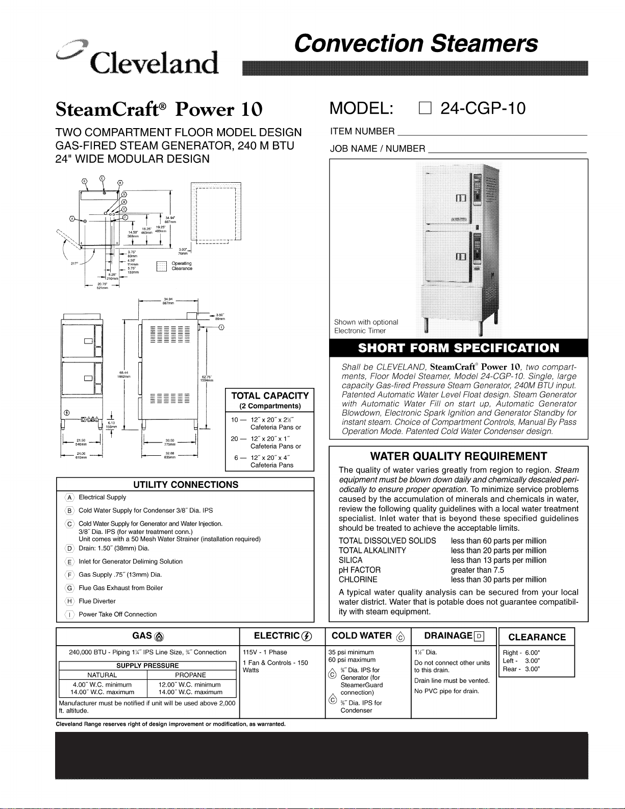
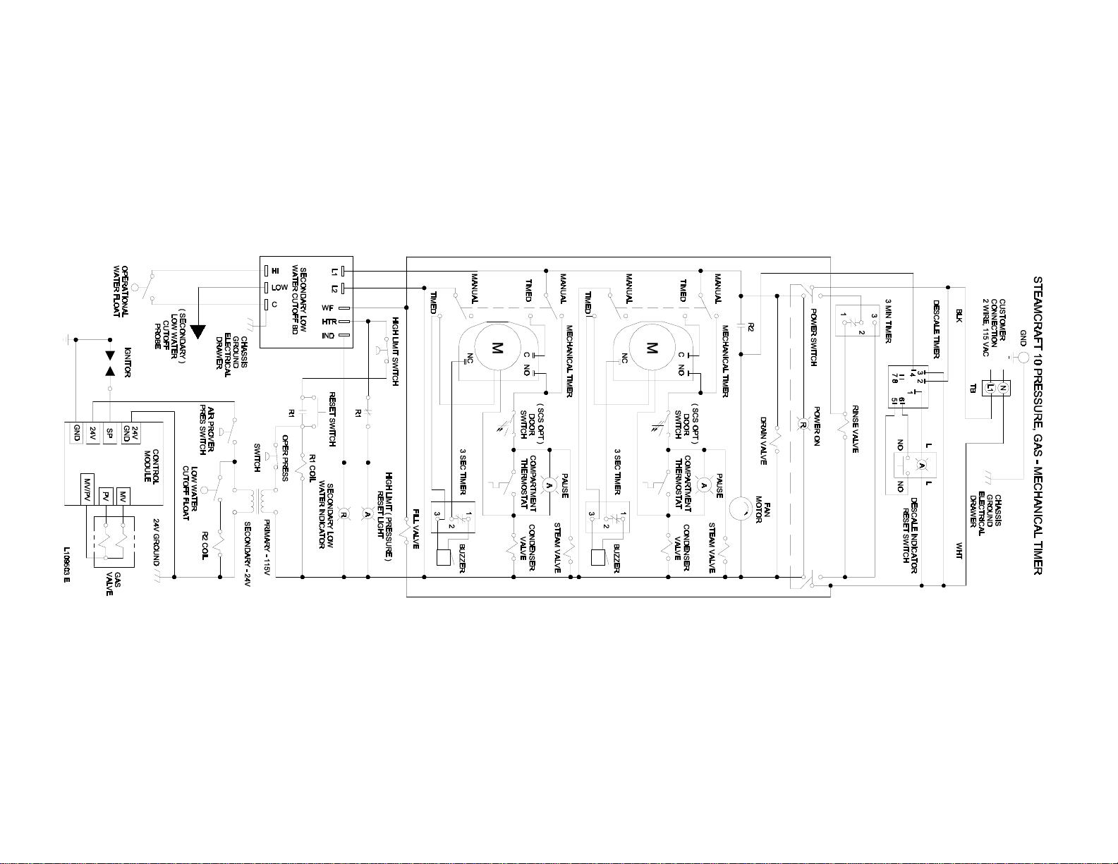
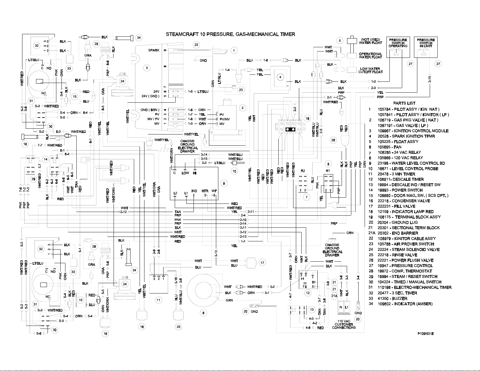
SEQUENCE OF OPERATIONS
24CGP10
Mechanical Timer
1. To turn the unit on, depress the red on/off rocker switch.
• 115 VAC is sent to normally open blowdown valve closing it.
• 115 VAC is sent to the Timed/Manual switches for the cabinets.
• 115 VAC is sent to L1 and L2 of the water level board.
2. With the water level board energized and no water in the boiler
• 115 VAC is sent from the IND terminal to the low water indicator light on the console.
• 115 VAC is sent from the WF terminal to the fill solenoid after a 5-second delay.
• The fill solenoid opens and the boiler fills.
• The water fills to the secondary low water cutoff probe in the boiler, shorting it to
ground
• 115 VAC is removed from the IND terminal and the low water indicator light is
de-energized.
• 115 VAC is sent from the HTR terminal through the normally closed contact of
the high-pressure switch to the amber reset switch,
• 115 VAC is sent through the normally closed R1 contacts to energize the amber
light.
• If the low water cut off probe is not grounded for 20 seconds, 115 VAC is
removed from HTR and sent back to IND energizing the low water light.
3. When the momentary amber switch is depressed 115 VAC is sent to the R1 relay closing it.
• The normally closed R1 contacts open de-energizing the amber light.
• The relay latches through the normally closed contacts of R1
• If either the high-pressure switch (set at 15 PSI) or the low probe circuit on the
water level board opens, then the latch circuit opens.
• When the water level or pressure returns to a safe condition the amber light will
energize and the process may begin again.
4. The R1 relay contacts close sending 115 VAC through the normally closed operating
pressure switch to the 24 VAC transformer.
• 24VAC is sent through the low water cutoff float switch to the R2 relay coil.
• The normally open R2 contacts close and send 115 VAC to the fan.
• The fan turns and the air prover switch is closed.
• 24 VAC is sent through the air prover switch to the ignition module.
• With 24 VAC to the ignition module 24VAC is sent to the pilot coil on the gas
valve.
• A spark is generated at the igniter.
• The pilot valve is energized and opens.
• Gas is sent to the pilot burner.
• The gas is ignited and the flame rectifies the AC current.

• When the ignition module reads 1.0 micro amps DC current through the
ground wire the coil to the main gas valve is energized
• The pilot flame lights the main burner.
• If the module does not read 1.0 micro amps DC in 90 seconds it will shut
down the main burner and make one more try before locking out.
5. The water in the boiler is heated to steam.
• As steam is generated and pressure builds the air is pushed out through the steamtrap
on the lower steam manifold.
• Steam goes through the steam trap heating it to 192 degrees closing the steam trap.
6. Pressure builds in the boiler to the set point of 8-10 PSI.
• The operating pressure switch opens and the heat circuit is de-energized.
7. With the timed/manual switch in the timed position and time on the timer.
• 115 VAC is sent to the steam solenoid and steam is sent to the cooking cabinet. There
the steam is directed around the product.
• 115 VAC is sent to the “Pause” or “Sure Cook” light.
• 115 VAC is sent to the normally open contacts of the compartment thermostat.
• The normally open contacts of the compartment thermostat close when the
compartment temperature reaches 193 degrees
• 115 VAC is sent to the timer motor and the timer begins to count down.
• 115 VAC is sent to the condensate solenoid and cold water is sent to the condensate
spray nozzle pulling the steam down the drain.
• When the steam pressure drops below the operating set point the heat circuit is
energized and the heat process begins again.
8. Water continues to fill the boiler until the operational water float is lifted and closes, shorting
the HI terminal on the water level board to the C terminal. .
• When the HI terminal is shorted to the C terminal the WF terminal on the water level
board is de-energized.
• If the water level drops below the operational water float switch for more than 5
seconds the WF terminal is energized and the water fill circuit begins again.
9. When the mechanical timer counts down:
• 115 VAC is removed from the condensate circuit.
• 115 VAC is removed from the steam solenoid.
• 115 VAC is sent to the 3-second timer
• 115 VAC is sent from the 3-second timer to the buzzer for 3 seconds.
10. With the timed/manual switch in the Manual position
• 115 VAC is sent to the steam solenoid and steam is sent to the cooking cabinet. There
the steam is directed around the product.
• 115 VAC is sent to the “Pause” or “Sure Cook” light.
• 115 VAC is sent to the normally open contacts of the compartment thermostat.
• The normally open contacts of the compartment thermostat close when the
compartment temperature reaches 193 degrees

• 115 VAC is sent to the condensate solenoid and cold water is sent to the condensate
spray nozzle pulling the steam down the drain.
• When the steam pressure drops below the operating set point the heat circuit is energized
and the heat process begins again.
11. The unit is turned off by depressing the red rocker switch.
• 115 VAC is removed from the timing and heat circuits.
• 115 VAC is removed from the normally open blowdown valve allowing the unit to
drain.
• 115 VAC is sent to the 3-minute timer.
• The three-minute timer will energize the fill and rinse solenoids for 3 minutes while
the steamer drains assisting and cooling the blowdown. .
 Loading...