

Cleveland 24-CGM-250 Service Manual

Cleveland Range
UNITED STATES
CANADA
REPAIR MANUAL
24/36CEM24/36/48
24/36/CGM200/250/300
24/36CDM
Model No. 24/36CSM
Cleveland Range, Inc.
1333 East 179th St.
Cleveland, Ohio 44110
Phone: (216) 481-4900 • FAX: (216) 481-3782
Garland commercial Ranges • 1777 Kamato Rd.
Mississauga, Ontario CN L4W 1X4
Phone: (416) 624-0260 • FAX: (416) 624-0623
FCS-02

Installation, Use and Care Instructions
INSTALLATION
nected
to
electricity must be grounded by the installer. A
Printe
d
6/90
Cleveland Range, Inc.
Convection Steamer
INSTALLATION SAFETY
WARNING
Installation of this equipment must be accomplished
by qualified installation personnel, working to all
applicable local and national codes. Improper
installation of the product could cause injury or
damage.
DO NOT store or use gasoline or other flammable
vapors and liquids in the vicinity of this or any other
appliance.
The flooring that will be directly under the boiler must
also be made of a noncombustible material.
Cleveland Range equipment is designed and built to comply
with applicable standards for manufacturers. Included
among those certification agencies which have approved the
safety of the equipment design and construction are: UL,
A.G.A., NSF, ASME, CSA, CGA., and others.
Cleveland Range equipment is designed and certified for
safe operation only when permanently installed in
accordance with local and/or national codes. Many local
codes exist and it is the responsibility of the owner and
installer to comply with these codes.
In no event shall Cleveland Range assume any liability for
consequential damage or injury resulting from installations
which are not in strict compliance with our installation instructions. Specifically, Cleveland Range will not assume
any liability for damage or injury resulting from improper
installation of equipment, including, but not limited to,
temporary or mobile installations.
INSTALLATION INSTRUCTIONS
1. These instructions must be retained by the owner/user for
future reference. Gas-fired boilers are only to be installed
in noncombustible areas that have provisions for
adequate air supply. The term "boiler" will be used
synonymously with "steam generator".
2. Position: For proper operation and drainage, the equipment must be level. It should be placed next to an open
floor drain. DO NOT POSITION THE UNIT DIRECT LY
ABOVE THE FLOOR DRAIN. Observe all clearance
requirements to provide air supply for proper operation,
as well as sufficient clearance for servicing. The
surrounding area must be free and dear of combustibles.
Dimensions and clearance specifications are shown on
the specification sheet.
3. Install in accordance with local codes and/or the National
Electric Code ANSI/NFPA No. 70-1987. Installation in
Canada must be in accordance with the Canadian
Electrical Code CSA Standard C22.1. Equipment that is
con-
wiring diagram is provided inside the base cabinet.
WARNING
INJURY TO PERSONNEL AND EQUIPMENT DA MAGE
may result from an improper drain connection.
4. The drain line outlet discharges exhaust steam and hot
condensate. Connect 1-1/2-inch IPS piping (or larger) to
extend the drain line to a nearby open floor drain. Up 10
two elbows and six feet of 1-1/2-inch IPS (or larger) extension pipe should be connected to the drain termination.
Drain piping extended six to twelve feet or using three
elbows, should be increased to 2-inch IPS. No more than
two pieces of Cleveland Range equipment should be connected to one common drain line. The maximum length of
extension from the drain termination should not exceed six
feet and use no more than two elbows. The extension
piping must have a gravity flow and vent freely to the air.
This drain outlet must be free-vented to avoid the creation
of back pressure in the steamer cooking compartments.
To ensure a vented drain line, DO NOT, UNDER ANY
CIRCUMSTANCES, CONNECT THE DRAIN OUT LET
DIRECTLY TO THE FLOOR DRAIN OR SEWER LINE.
Do not run the drain line discharge int o PVC drain piping
or any other drain piping material not capable of sustaining
180º F operation.
NOTE: Direct-steam connected pressure steamers do not
require a cold water connection, and therefore steps
5 and 6 do not apply. Refer directly to step 7. A kettle
fill faucet, if so equipped, requires a hot and/or cold
water connection. The data contained in step 5 for
cold water also applies to hot water.
5. Connect COLD water supply plumbing to the line strainer.
(Never connect hot water to the boiler water fill line
strainer.) Constant flow pressure must be maintained
between 35 and 60 psi, and not experience a pressure
drop below 35 psi when other appliances are used. If the
water pressure exceeds 60 psi, a pressure reducing valve
must be installed in the water supply plumbing to reduce
the water pressure to less than 60 psi. Locations and
pressure data are shown on the specification sheet. 1/4inch IPS plumb ing is sufficient for water supply lines up to
20 feet in length, but water supply lines longer than 20 feet
should be at least 3/8-inch IPS. Flush water supply lines
thoroughly before connecting them to the unit. Use water
which is low in total dissolved solids content and low in
gas content to prevent internal scaling, pitting and
corrosion of the steam generator, and carry -over of
minerals into the steam. Water which is fit to drink can still
contain highly detrimental impurities.
NOTE: If equipped with a kettle and kettle water fill swing
spout, 3/8-inch (10mm) hot and/or cold water connection(s) will be required at the swing spout valve.
6. Turn on the cold water supply to the unit. Ensure that the
manual water valve, inside the base cabinet, is open.

Cleveland Range, Inc.
Printed 6/90
Installation, Use and Care Instructions
Convection Steamer
7. Connect the primary fuel supply in accordance with the
following instructions. Location and other data are shown
on the specification sheet.
For Gas-Fired Steam Generators; Post in a prominent
location, instructions to be followed in the event the user
smells gas. This information shall be obtained by consult ing the local gas supplier. Install a sediment trap (drip leg)
in the gas supply line, then connect gas supply piping to
the boiler gas valve piping. GAS-FIRED EQUIPMENT IS
DESIGNED FOR INSTALLATION ONLY IN NONCOMBUSTIBLE LOCATIONS. THIS INCLUDES THE
FLOORING THAT WILL BE DIRECTLY UNDER THE
EQUIPMENT. Location, plumbing size, and pressure data
are shown on the specification sheet. Boilers rated at less
that 225,000 BTU require 3/4-inch IPS gas supply piping,
and boilers rated at 225,000 BTU or more require 1-inch
IPS gas supply piping. Natural gas pressure must be
between 4" -14" water column, and L-P gas supply
pressure must be between 12" - 14" water column.
NEVER EXCEED 14" WATER COLUMN (1/2 psi) GAS
PRESSURE. If the gas supply pressure exceeds 14"
water column, a pressure regulating valve must be
installed in the gas supply plumbing to reduce the gas
pressure to less that 14" water column. Installation must
be in accordance with local codes, or in the absence of
local codes, with the National Fuel Gas Code, ANSI
2223.1-1984. Installation in Canada must be in
accordance with installation codes for Gas Burning
Appliances and Equipment B149.1 and B149.2. Use a
gas pipe joint compound which is resistant to LP gas.
Turn the gas valve control knob to ON (the word "on" on
the knob will be opposite the index on the valve's body).
Test all pipe joints for leaks with soap and water solution.
Never obstruct the flow of combustion and ventilation air.
Observe all clearance requirements to provide adequate
air openings into the combustion chamber. The appliance
and its individual shut -off valve must be disconnected
from the gas supply piping system during any pressure
testing of that system at test pressures in excess of 14"
water column (1/2 psi or 3.45 kPa). The appliance must
be isolated from the gas supply piping system at test
pressures equal to or less than 14" water column (1/2 psi
or 3.45 kPa). A permanent 115-volt electrical connection
is required at the junction box. The junction box location is
shown on the specification sheet. The unit must be
electrically grounded by the installer.
For Electric Powered Steam Generators: Connect electric
power: location and data are shown on the specification
sheet. Provide connection as required by the unit; either
directly to the single contactor, or to the terminal block
(when equipped with multiple contactors). Electric supply
must match power requireme nts specified on the data
plate inside the base cabinet. The copper wiring must be
adequate to carry the required current at the rated
voltage. A separate fused disconnect switch must be
supplied and installed. The unit must be electrically
grounded by the installer.
For Steam Coil Steam Generators: Connect steam supply
piping to the input side of the steam coil. Location and
pressure data are shown on the specification sheet. Incoming steam pressure must be regulated between 35 and 45
psi. A 3/4-inch strainer, equipped with a 20 mesh stainless
steel screen, must be supplied and installed at the incoming
steam connection point. Flush the steam line thoroughly
before connecting it to the boiler. To ensure an adequate
volume of steam, the branch steam supply line must be 3/4inch IPS minimum. Connect the inverted bucket trap to the
outlet end of the steam coil. Fill the trap with water before
installing it. A permanent 115-volt electrical connection is
required at the junction box. The junction box location is
shown on the specification sheet. The unit mast be
electrically-grounded by the installer.
For Direct-Steam Connected Steamers/Kettles: Connect
steam supply piping to the input side of the line strainer.
Location and pressure data are shown on the specification
sheet. Flush the steam line thoroughly before connecting it
to the steamer. To ensure an adequate volume of steam, the
branch steam supply line must be 3/4-inch IPS minimum.
(Direct-steam -connected kettles require 1/2-inch IPS pipe if
the kettle total capacity is 20 gallons or less, and 3/4-inch
IPS pipe if the total capacity exceeds 20 gallons.) A
permanent 115-volt electrical connection is required at the
junction box. The junction box location is shown on the
specification sheet. The unit must be electrically grounded
by the installer.
Installation Checks
Proper operation of the Cleveland Convection Steamer is
dependent upon proper installation. After the steamer has
been installed, a few quick checks could save unnecessary
service calls.
1. The unit must be level.
2 The Convection Steamer requires a cold water connection
for proper, efficient operation. DO NOT USE HOT WATER.
The cold water must be connected to the line strainer,
located at the front lower-right of the steamer base.
3. Check that the manual water supply valve is open.
4. Check all water supply lines and valves for leaks.
5. Check that the water supply pressure and water quality meet
the requirements of installation paragraph 5.
6. On electric units, verify that the supply voltage meets the
voltage requirements on the rating plate inside the base
cabinet, and the voltage shown on the packing slip. Verify
that the unit is protected with a separate fused disconnect,
and is property grounded in accordance with the National
Electric Code.
7. On gas, steam coil, and direct-steam -connected units, verify
that there is a 115-Volt connection at the handi-box located
on the left side of the base at the bottom front.
Printed 6/90 Cleveland Range, Inc.
Installation, Use and Care Instructions
Convection Steamer
8. On steam coil units, the incoming steam pressure must
be 35 to 50 psi. Less than 35 psi will not effectively
operate the unit. Pressure in excess of 50 psi must be
reduced (with a pressure reducing valve) to 35 to 50 psi.
WARNING
INJURY TO PERSONNEL AND EQUIPMENT DAMAGE
may result from an improper drain connection.
9. Check that the drain lines meet the installation requirements specified in installation paragraph 4.
10. After completing checks 1 through 9, and correcting
any deficiencies, refer to the Start-up and Preheat
instructions in the Operation section. Verify that the unit
operates properly, and make checks 11 and 12.
11. Check to ensure that the water in the boiler sight gage
glass automatically stays about 1/3 full when the boiler
is started up and operated.
12. Check to ensure that the steam pressure gage
registers 10 psi.
The steam pressure is factory -adjusted to provide the
proper pressure. In some cases, however, the factory
setting may shift due to shaking in transit; and resetting
will be required after installation. Proper adjustments
and maintenance procedures are detailed on a separate
data sheet entitled "Steam Pressure Adjustments."
Adjustments should be made only by qualified service
personnel. The factory pressure settings shown in the
accompanying chart should never be exceeded.
Gage Pressure Reading with No Steam
Flow* (Static Pressure)
Self-Contained Steam Generator. Gas or Electric
Operating Pressure Switch 10 psi
High Limit Safety Pressure Switch 15 psi
OPERATION
Operation of the Cleveland Range Convection Steamer is very
easy. Each operator should read and understand the following
procedures to effectively start, operate, and shut down the
steamer each day. The owner(s) and operator(s) of this
equipment should be aware that live steam can cause serious
injuries, and pay particular attention to the WARNINGS in this
text. These instructions are to be retained by the owner(s) and
operator(s) for future reference.
Controls and Control Panels
There are two steam generator control arrangements and two
steamer compartment control panels available for Cleveland
Range Convection Steamers. The steam generator controls are
illustrated in Figure 1. The steamer compartment control panels
are illustrated in Figures 2 and 3. Compare these figures with
the equipment supplied, and identify which control and panel
combinations apply.
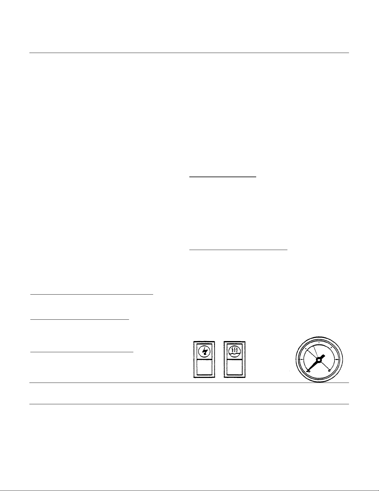
Steam Generator Controls
The steam generator controls are located on the front face of
the steamer base unit. The switches are to the left of the
pressure gage, as illustrated in Figure 1. Most Cleveland
Range Convection Steamers have a steam generator built into
the base unit which supplies steam to the cooking compartments. However, an external steam supply may also be used.
Units with a built -in boiler have both the POWER rocker switch
and the STEAM momentary switch next to the pressure gauge.
Units with an external steam supply have the POWER rocker
switch only. They do not have the STEAM momentary switch.
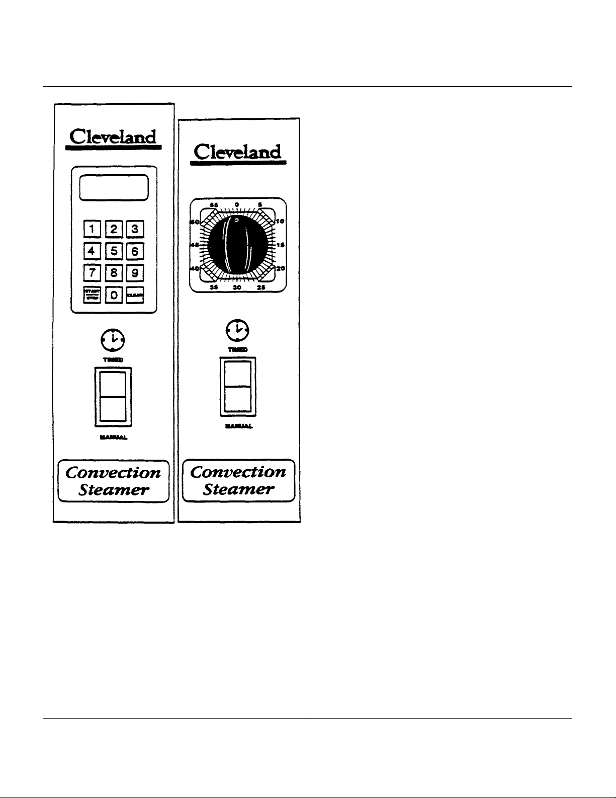
Steamer Compartment Control Panels
Figure 2 illustrates the standard electronic controls: the Key
Pad Control Panel. This panel has a rocker switch, a key pad,
and a digital timer. Figure 3 illustrates the optional electromechanical controls: the Dial Timer Control Panel. This panel
has a rocker switch and dial timer. Steamer functions are the
same for both the standard and optional panel configurations.
Operating details are slightly different especially when setting
the automatic operating time. For clarity, two sets of
instructions are provided for cooking operations.
Self-Contained Steam Coil Generator
Operating Pressure Switch 10 psi
High Limit Safety Pressure Switch 15 psi
Steam Supply Pressure Range 35-45 psi
Direct-Connect (to House Steam Supply)
Steamer Pressure Reducing Valve 10 psi
Steam Supply Pressure Range 15-45 psi
*with or without kettle
Figure l. Steam Generator Controls
Installation, Use and Care Instructions
Figure
3.
Dial Timer Control
Clev
eland Range, Inc.
Printed
6/90
Convection Steamer
Figure 2. Key Pad Control
Panel
Start-up and Preheat
WARNING
Do not attempt to start or operate the Convection
Steamer during a power failure. Critical safety circuits
are not energized, and serious injury to personnel or
damage to equipment may result.
1. Inspect the steamer. Check the cooking compartments to
ensure that the steam tubes and drain screens are in place
and secure. Check inside the steamer base cabinet to ensure that the manual drain valve is closed and the manual
water supply valve is open.
Panel
2. Start the steam supply. The steam supply is either an
integral steam generator (boiler) built into the base unit or
an external steam supply.
• For units without a built -in boiler, refer to the start-up
procedures for the external steam supply and be sure it
is running property. As soon as the pressure gauge on
the Convection Steamer registers 10 psi, steamer
preheating may begin. Skip the remainder of step 2, and
begin step 3.
• For units with a built -in boiler, fill the boiler with water and
start the steam generator as described in steps a
through d below.
a. Press the ON end of the POWER on-off rocker switch
located next to the steam pressure gauge (Figure-l).
The red indicator light in the POWER rocker switch
turns on and the steam generator begins to fill with
water. This takes about 5 minutes.
b. When the water level in the steam generator reaches a
safe operating level, the amber light in the STEAM
momentary switch turns on. Whenever the amber light is
on, the heaters, steam supply, or burners are off, and no
steam is being generated. The energy source (electric,
gas, etc.) cannot be activated until the boiler cont ains
sufficient water, indicated by the amber light.
c. Press the STEAM momentary switch to produce steam in
the boiler. This activates the energy source (electric
heaters, gas burners, or steam solenoid valve) and the
amber light turns off:
The STEAM swit ch must be pressed to re-start the
steamer after it is shut off for any reason (including a
brief power interruption). No attempt should be made to
operate the equipment during a power failure.
NOTE: For steamers with built -in gas-fired boilers:
If the burners fail to ignite in four seconds, a safety
circuit de-energizes the system. In this event, toggle
the POWER rocker switch to the OFF position and
back to the ON position. The amber light in the
STEAM momentary switch lights. Wait five minutes,
then press the STEAM momentary switch to start the
burner ignition cycle once again.
d. About 20 minutes after starting the boiler in step c. the
steam pressure gauge on the unit base should register
10 psi.
3. Preheat the Convection Steamer cooking compartme nts.
For accurate, efficient cooking times, the cooking compartments should be preheated during startup.
NOTE: With a steamer/kettle combination, if both must be
used at the same time, always heat the kettle first.
When kettle contents begin to simmer, and steam
pressure returns, the steamer compartments may be
preheated.
a. Close the compartment door by gently swinging it shut.
b. Refer to timer setting instructions under Automatic
Operation for the appropriate control panel. Set the

Installation, Use and Care Instructions
Convection Steamer
timer for each compartment to one minute, and start
the cooking cycles. Steaming begins in each
compartment.
NOTE: On Convection Steamers equipped with electronic
key pad control panels, the timer does not begin
counting down until the cooking compartment
reaches operating temperature. This may take 2
or 3 minutes if the steamer has not been
operating.
c. Steaming continues for the set one minute. When the
preheating is completed, the steam aut omatically
shuts off and a 3-second alarm sounds. The
Convection Steamer is ready for cooking operations.
3. If food inspection is required during steaming, refer to the
LIVE STEAM WARNING above. Use extreme caution
when opening the steamer door during steaming operations.
4. Although the timer cannot turn the steam off in manual
mode, it can be used as a conventional cooking timer.
Refer to the timer setting instructions under Automatic
Operation and set the timer. The timer will count down the
set period and sound the buzzer, but IT WILL NOT TURN
OFF THE STEAM-AFTER THE ALARM SOUNDS.
5. To STOP the flow of steam, press the Timed end of the
MANUAL/TIMED rocker switch. Steam stops flowing int o
the cooking compartment.
COOKING OPERATIONS
The control panels mounted on the cooking compartments
regulate cooking operations. Although cooking operations
are similar for all Convection Steamers, regardless of
control panel configuration, separate instructions are
provided for each control panel type.
Cooking Operations for
The Key Pad Control Panel
The electronic keypad control panel is illustrated in
Figure 2.
The Cleveland Range Convection Steamer has two
cooking modes: Manual and Automatic. The Manual Mode
provides continuous steaming and is turned on and off by
the MANUAL/TIMED rocker switch. The Automatic Mode
monitors cooking time and compartment temperature to
provide accurate, efficient, uniform steam cooking.
NOTE: Whether using timed or manual cooking modes,
optimum steam heat transfer, and therefore a
higher quality food product, is achieved when
shallow, perforated, uncovered pans are used.
WARNING
LIVE STEAM may cause severe burns. Use extreme
caution when opening the steamer door. Turn lace away
from the steamer when first opening the door. Do not look
into the cooking compartment until steam has cleared.
KEEP HANDS OUT OF THE COOKING
COMPARTMENT TO PREVENT BURNS.
Manual Cooking Operation - Key Pad Controls
Use manual mode for a continuous supply of steam for
long periods, or if the required cooking time is unknown
and frequent inspection is required.
1. Place the pan(s) of food into the cooking compartment.
2. To START the flow of steam, press the MANUAL end of
the MANUAL/TIMED rocker switch, located below the
timer. Steam immediately starts flowing into the cooking
compartment.
Automatic Cooking Operation - Key Pad Controls
Each Convection Steamer cooking compartment is equipped
with an independent electronic digital timer, which has a
maximum setting of 99 minutes and 99 seconds. Each timer
is connected to a temperature sensing device in the cooking
compartment. THE SENSOR CIRCUIT ALLOWS THE TIMER
TO COUNTDOWN ONLY WHEN THE COOKING
COMPARTMENT IS AT THE PROPER COOKING
TEMPERATURE. This assures uniformity in the cooking
times as the timer automatically compensates for food
product defrosting and/or beat -up time.
1. Place the pan(s) of food into the cooking compartment.
2. Clear and reset the timer. The timer can be set only when
the COOKING TIME display is clear. Press the CLEAR
key on the number pad to zero the timer.
3. Set the Desired Cooking Time. The cooking time display
contains four digits. The left two digits are minutes, and the
right two digits are seconds. The display 12:34 is set for 12
minutes and 34 seconds.
a. To set the cooking time: change the required cooking
time to minutes and seconds, press the number keys
for the minutes, and then press the number keys for the
seconds. If the cooking time is 99 seconds or less, only
press the number keys for seconds.
b. Example 1. To set the timer for 1 hour and 15 minutes:
Change 1 hour (60 min) and 15 minutes to 75 minutes.
Press the following number keys in sequence: 7500.
The display will read 75:00 when properly set for 1 hour
and 15 minutes.
c. Example 2. To clear the time numbers set in example 1,
press the CLEAR key on the number pad. The display
returns to 00:00.
d. Example 3. To set the timer for 1.5 minutes: Change the
time to 1 minute and 30 seconds. Press the following
number keys in sequence: 130. The display will read
01:30, when set for 1. 5 minutes. All seconds method:
Change the 1.5 minutes to 90 seconds and press 90.
The display will read 00:90, when set for 1.5 minutes.
Printed 6/90 Cleveland Range, Inc.

Installation, Use and Care Instructions
Convection Steamer
4. Press the START/STOP key to Start the timer. When the
START/STOP key is pressed, steam enters the cooking
compartment.
a. THE TIMER WILL BEGIN TO COUNT DOWN
ONLY AFTER THE COOKING COMPARTMENT
REACHES PROPER COOKING TEMPERATURE.
The timer automatically delays to compensate for
defrosting and/or food product heat-up time.
b. For example, a timer setting of 10 minutes may in fact
take 11 or 12 minutes for the timer to count down
and the alarm to sound. This is normal. Heating the
compartment and food to cooking temperature uses
the additional time.
c. To stop or reset the timer, press and hold the
START/STOP key. The cooking time display returns
to the last time setting.
• To resort the same time, press the START/STOP
key.
• To set a new time press the CLEAR key, and set
the new time.
5. When the timer counts down to zero, an alarm sounds
continuously. Press the START/STOP key to silence the
alarm. The cooking time display returns to the last time
setting. Either run this same setting again or dear and
reset the timer.
6. Example 4. To cook two 14 minutes cycles: Press the
CLEAR key to dear the timer. Press the following
number keys in sequence: 1400. The display shows
14:00. Press the START/STOP key to start the timer.
When the display counts down to zero, the alarm sounds.
Press the START/STOP key, and the display returns to
14:00. Press the START/STOP key to start the second
14 minute cycle.
Cooking Operations for
The Dial Timer Control Panel
The dial timer control panel is illustrated in Figure 3.
The Cleveland Convection Steamer has two cooking
modes:
Manual and Automatic. The Manual Mode provides continuous steaming and is turned on and off by the
MANUA/TIMED rocker switch. The Automatic Mode
monitors cooking time to provide accurate, efficient, steam
cooking.
NOTE: Whether using timed or manual cooking modes,
optimum steam beat transfer, and therefore a
higher quality food product, is achieved when
shallow, per forated, uncovered pans are used.
WARNING
LIVE STEAM may cause severe bums. Use extreme
caution when opening the steamer door. Turn face away
from the steamer when first opening the door. Do not look
into the cooking compartment until steam has cleared.
KEEP HANDS OUT OF THE COOKING COMPARTMENT TO PREVENT BURNS.
Cleveland Range. Inc, Printed 6/90
Manual Cooking Operation - Dial Timer Controls
Use Manual mode for a continuous supply of steam for
periods longer than the timer limits (99 minutes), or if the
required cooking time is unknown and frequent inspection is
required.
1 Place the pan(s) of food into the cooking
compartment.
2. To START the flow of steam, press the MANUAL end
of the MANUAL/TIMED rocker switch, located below
the timer.
3. If food inspection is required during steaming, refer to the
LIVE STEAM WARNING above. Use extreme caution
when opening the steamer door during steaming operations.
4. Although the timer cannot turn the steam off in manual
mode, it can be used as a conventional cooking timer.
Refer to the timer setting instructions under Automatic
Operation and set the timer. The timer will count down the
set period and sound the buzzer, but IT WILL NOT
TURN OFF THE STEAM AFTER THE ALARM
SOUNDS.
5. To STOP the flow of steam, press the Timed end of
the MANUAL/TIMED rocker switch.
Automatic Cooking Operation
Dial Timer Controls
Each Convection Steamer cooking compartment is
equipped with an independent dial timer. This timer
controls the cook ing compartment steaming cycle. Use
automatic mode when an exact cooking time is required.
Steam cooking begins when
the timer is set, and automatically stops when the timer
counts
down the set period.
1 Check that the MANUAL/TIMED rocker switch is in the
TIMED position. If it is not, press the TIMED end of the
MANUAL/TIMED rocker switch,
2. Place the pan(s) of food into the cooking
compartment.
3. Set the Desired Cooking Time, Turn the dial anal it points
to the desired cooking time, When the dial timer is set,
steam enters the cooking compartment,
4. When the timer counts down to zero, an alarm sounds for 4
seconds, and steam flow into the cooking compartment
stops,
Boiler Shutdown
The red-lighted power switch must be shut off for 3 minutes a
minimum of once every 8 hours 10 automatically drain highly
mineralized water from the boiler, which reduces the formation of scale, See step 1 in CARE AND CLEANING instructions, which follow.

Printed
6/90
Cleveland Range, Inc.
Installation, Use and Care Instructions
Convection Steamer
CARE AND CLEANING
The Cleveland Convection Steamer most be cleaned
regularly to maintain its fast, efficient cooking performance,
and to ensure its continued safe, reliable operation
1. The boiler must be drained (blowdown) after a maximum
of 8 hours of use. If the boiler feedwater contains more
than 60 pans per million of total dissolved solids, the
boiler most have a blowdown more often, the frequency
depending upon the mineral content of the feedwater.
Blowdown means the boiler must be drained under
pres sure.
THE BOILER BLOWDOWN IS PERFORMED BY
SIMPLY SHUTTING OFF THE STEAMER'S REDLIGHTED POWER SWITCH WHILE THE BOILER IS AT
NORMAL 10 PSI OPERATING PRESSURE. WHEN
THE BOTTOM OF THE POWER ROCKER SWITCH IS
PRESSED, ITS RED LIGHT GOES OUT, AND THE
DRAIN VALVE AUTOMATICALLY OPENS, DRAINING
THE BOILER. AN AUTOMATICALLY-TIMED DRAIN
WATER CONDENSER WILL FLUSH THE DRAIN FOR
3 MINUTES, THEN SHUT OFF. AFTER 3 MINUTES
THE STEAMER IS READY TO BE RESTARTED.
When steam is produced, the water in the boiler is being
distilled. During this process, the minerals that come into
the boiler with the water, remain in the boiler as the
water boils away as steam. When allowed to
accumulate, the water becomes highly mineralized,
which results in erratic operation, lime build-up,
corrosion, and premature electric heater failures- In
some cases, complete boiler replacement becomes
necessary, which is extremely ex pensive. By draining
the boiler under pressure, most sediment present will be
flushed down the drain.
2. The steamer is equipped with a drain in the back of the
cooking compartment. No compartment should be
operated without the drain screen in place. This screen
prevents large food particles from entering and possibly
plugging the drain line. Any restriction of the drain line
may cause a slight build-up of back pressure in the
compartment, resulting in steam leaks around the door
gasket. It also may adversely affect the convection
action of the steam in the compartment, which is critical
to optimum performance- Pouring USDA approved
drain cleaner through the compartment drains once a
week will help to ensure an open drain. A manual (hand
crank) drain auger, or "snake", may be safely used to
dear obstructions in the compartment drains. Do not
use a power auger, as damage to the plastic drain
system will result.
With the steamer off, open the cooking compartment
doors and allow the steamer to cool before cleaning the
cooking compartments and their components.
3. At the end of each day's operation, wash the pan slides,
steam tubes, door gaskets, and compartment interiors
with mild detergent and warm water, either by hand or
in a dishwasher. Rinse thoroughly with clear water.
Rinse water should drain freely through the
compartment drain
openings. If it docs not, the drain must be cleaned before
using the steamer.
4. Once a week, remove the steam tubes and clean the
orifices. First, remove the pan slides by lifting upward and
toward the center of the compartment. Pressing backward
on the steam tube will allow its front eyelet to clear the
compartment stud. The tube is then angled toward the
center of the compartment just enough to dear the stud
and be pulled forward, out of its socket. The orifices can
be cleaned easily with a paper dip. Then, thoroughly wash
and rinse all steam tubes. This can be done in a
dishwasher. Lubricate each tube's tapered end with
cooking oil before replacing in the steamers
compartments. Be sure all four steam tubes are securely
in place before activating the compartment. The tubes are
interchangeable and may be placed in any spot in either
compartment.
5. To prolong door gasket life, always leave compartment
door ajar when not in use.
6. Exterior Care: Allow steamer to cool before washing. Use
the same cleaners and cleaning procedures as for other
kitchen surfaces of stainless steel and aluminum. Mild
soapy water, with a dear water rinse, is recommended. Do
not allow water to run into electrical controls. Always turn
off equipment power before using water to wash equipment. Do not hose down the steamer.
WARNING
Do not store or use gasoline or other flammable
vapors and liquids in the vicinity of this or any other
appliance.
MAINTENANCE
Periodically, a qualified serviceman should be summoned for
routine preventive maintenance.
1. The blowdown procedure will not completely remove the
mineral deposits that adhere to the top of the boiler. A
chemical descaling should be done by a boiler treatme nt
specialist. This should be done once a year in average
water conditions, but in poor water areas it may be needed
two or three times a year.
2. Periodic boiler inspection should be made by a
qualified serviceman.
3. Once every three months, the cold wat er line strainer
should be cleaned.
Cleveland Range supports a comprehensive network of
Maintenance and Repair Centers (regional pans and service
dis tributors) throughout the United States and Canada.
Please contact your nearest distributor for the name of an
authorized service agency in your area, or for replacement
pans and information regarding the proper maintenance and
repair of Cleveland Range equipment. In order to maintain
the various agency safety certifications, only factory -supplied
replacement pans should be used. The use of Other than
factory-supplied replacement pans will void the warranty.
COMPARTMENT CONTROL - ELECTRONIC TIMER 104124

CONVECTION STEAMER TIMER SETTINGS
Asparagus, spears
4 6 Fresh Frozen
Beans, green
2"
cut 6 5 Clams in shell
3-5 French cut
4
5** Cod fillets.
5
oz. portions
3 4
whole
6 4
Crab legs. king
4-6 Broccoli, spears
3 2-3
Snow c
rab- 2-4
flowerettes
2-3 1-2
Crab, live.
4 oz. 4
chopped
8 3/4 - 1 Ib 12
Brussels sprouts
4-5 4
Halibut,
6-8 oz.
portions
4-6 6-8
Cabbage
Lobster, whole.
1
Ib. 7-9
12-16
wedges/head
4 Lobster tails,
8 oz. 8-10
Cabbage,
defroste
d, butterflied
4-6 whole
- to remove leaves
2 Mussels in shell
2 for cabbage rolls
Oysters in shell
2-4
Carrots, baby whole
10 6
Red snapper.
8
oz. 4-5 4-5
Salmon steak,
8
oz. 6 7
sliced, crinkle cut
7
-
8 3
4
10
3
diced
2
1
3
&
on cob, cobbettes
6
12** Hard cooked for egg salad,
Eggplant, sliced, diced
1 potato salad
10-12 Mixed vegetables
3-4 Soft cooked
3
Coddled
6
Potatoes, whole
8 oz. 30-35
Blanch for peeling
peeled, quartered, fresh
12-19 Fresh: Avocado
1 peeled, diced
8-10 Apple, cored
1 Potatoes, sweet, whole
30-35 Grapefruit
1
Spinach leaf
2 21** Orange
1
chopped
21**
Apricot
1 Squash, acorn halves
15 Pineapple whole
2
butternut, quartered
7
Dried*: add water to re
-
hydrate
whipped*
20** Apple
10
spaghetti squash, halves
15-18 Apncot
10
Tomatoes, whole sliced*
1 Peach
10
Turnips, whole
20-25 Pear 10
.Zucchini. sliced
2-4 2-4
Prune
10
Timer settings are approximate due to the differences in food quality, age, shape and the degree of doneness desired. It is not
necessary to add water. Perforated pans are recommended. Starred items (*) must be cooked in solid pans or containers. Items marked with
two stars (**) require handling in two steps. First, steam for approximately 1/2 the time shown, remove from steamer, separate thawed portion,
or stir, and return to the steamer for the time remaining. The compensating feature of the timer allows the cooking compartment to reach
cooking temperature before the preset time starts to count up.
(In Minutes)
VEGETABLES: Fresh Frozen
Artichoke 12
SEAFOODS: Steam all seafoods on a perforated pan with catch pan.
(In Minutes)
diced 2
Cauliflower, flowerettes 4-5 3whole
Celery, diagonal cut 1 1/2"
minced Corn, yellow whole kernel 1 2 EGGS (Medium Sized):
Mushrooms, whole (1 1/2" dia.)
sliced
Onions, diced, sliced 2-3 1
whole 4 2
Peas, green
3 1
2 FRUITS:
Shrimp, 10 ct. per Ib. 1QF
5 Ib. block, peeled
deveined 30 ct.
5 Ib. block, green, 26-30 ct. (nested pan)
Poached in a cup
Scrambled* 6-7**
Cleveland reserves right of design improvement or modification, as warranted.
2-3
4-6
6-8**
10**

Steam meats and poultry in nested pans, as juices can be used for gravy,
sauces, beef stock and soups. The see of portion. thickness of cut. grade,
Chicken.
5-8
oz. breaded
pieces
18-20
mm.
Italian sausage
4
oz- portion
10
mm. Ribs. 3 Ib and down
20-26
min.
Ground chuck tor chili
4
min./lb.
4-6 min./lb.
Pot roast, choice
8-12
min/Ib.
Rump roas
t, choice
boned, rolled, tied
12
min /lb.
Meat loaf.
4
lb. loaf
5
min/lb.
Liver, baby beef.
8
oz. slice
2-4
min. 2-4
min. Corned beef.
6-8
Ib. cut,
time listed below produces a "rare"
steak. A "well done" steak is first steamed to the "rare" stage. then broiled or
4
min. 4
min. 4 min. 6
min. 3-4 min.
3 min. 4
mm. 4
min. 5
min.
12
oz. 7
mm.
T-bone —
12 oz.
5
min.
16
oz. 8
min.
18 oz.
8
min.
Full size pans
Cabbage
-
rolls, stuffed*
25
min. 20
min. cover with tomato
sauce & serve
Casserole dishes*
beef stew,
20-25
min. 25-30
min. stroganoff
20-25
min. 25-30
min. Lasagna*. freshly prepared
20-25
min. 25-30
mm
4
cups cold water/lb.
17
min.
Beans*, pre
-
soaked overnight.
1
to. beans
+
1 1/2 qts. water
45
min. Beans*, unsoak
ed.
1
Ib. beans
+
1 1
/2 qts.
water
2 1/2 hrs.
Lasagna noodles
10-12
min **
Macaroni, shells, elbow
10-12
mm. **
Rigatoni
10
min. **
Spaghetti, vermicelli
8
min. **
CONVECTION STEAMER TIMER SETTINGS
(continued)
MEATS & POULTRY:
should be considered when selecting a timer setting tor doneness.
STEAKS:
Strip steak — 10 oz.
5 mm.
POULTRY: Fresh Frozen
Turkey, whole 6-8 min./lb. 6-8 min./lb.
halves, 1 1/4 - 1 1/2 Ib per
half 20-24 min. 20-24 min.
PORK, SAUSAGE, HOT DOGS:
Pork. Chop. 4 count/lb 10 min,
Hot dogs. 8 count/lb 2 min.
BEEF:
Cubes, 1 1/2" 6-7 min/lb. 6 min./lb.
add 1/2" water to pan 20-23 min/lb.
STEAKS:
Using a 3/4" to 1" steak, the steaming
grilled for 1 1/2 minutes on each side. This "well done" steak shrinks less, is
more tender and juicy: and. when served, is the same see as the "rare" steak.
Sirloin patties.
chopped. 8 oz.
Ribeye. 8 oz.
Top butt steak. 6 oz.
8 oz.
Filet Mignon. butterflied —
4 oz.
6 oz.
8 oz.
10 oz.
16 oz. Whole (Chateaubrand)
8 min.
22 oz. 10 min.
PREPARED ENTREES: Fresh Frozen
reheat each serving 4" 6-8 min. 12 min
DEHYDRATED FOODS:
Potatoes": 2 1/2# random sliced
plus 5 cups cold water/lb. 12 min.
RICE & BEANS:
Rice*, long grain
Refried beans*. 2 #10 cans 15-17 min.
PASTA:
Steam in nested pans. Place pasta on 2 1/2" perforated pan used as
a liner in a solid 2 1/2" pan. Cover pasta with cold water.
Egg noodles. 1 1/2" wide 4-6 mm. **
Spaghetti, regular
10 min. **
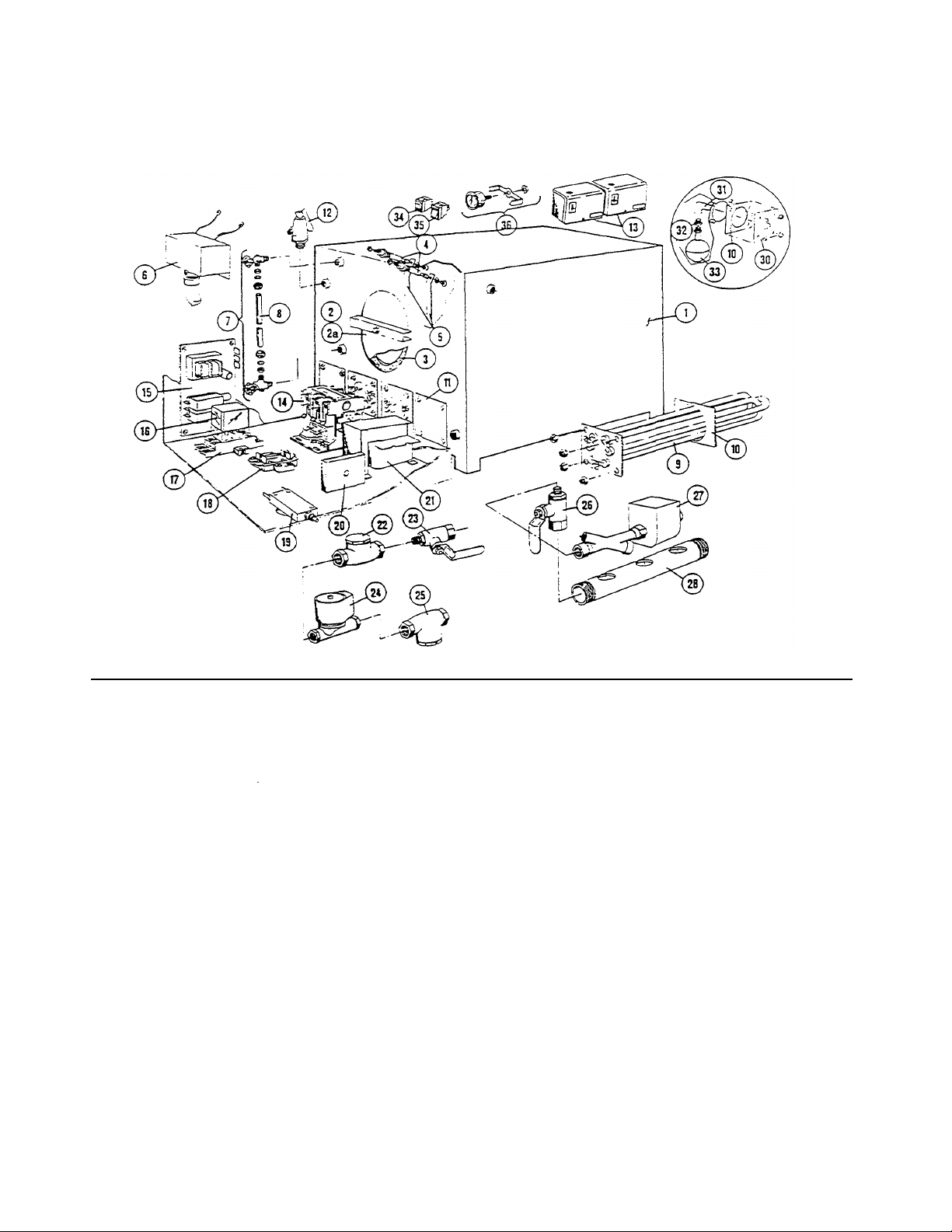
ELECTRIC STEAM GENERATOR (BOILER) ASSEMBLY - 2 PROBE TYPE
REFERENCE
NUMBER
PART
NUMBER
REFERENCE
NUMBER
PART
NUMBER
plate assembly, mounting studs tor
3"
flanged heater elements
10
07128
Heater Gasket
44149
Electric Boile
r Shell
(43894)
above, also
11 16546
3" Block
-
Off Plate
including sight gauge, two probes and
12 22131
15 psi Safely Valve
cover box.
22130
8 psi Safety Valve
Hand Hole Plate Assembly including bar.
and gasket.
14
03509
Contactor.
50
amp 2a 43748
Hand Hole Plate only
03506
Contactor.
75
amp 3 07106
Hand Hole Gasket.
4" x 6- oval 15 23198
Control Board, water level and LWCO
4 40462
Probe 16 03524
Relay
6 52305
Probe Cover Box
18
44168
Terminal Block.
2
pole 7 40445
Water Gauge Set with Glass
19
03202
Circuit Breaker,
l
amp
07108
Fibre Washer
(2
required)
20
20478
Interval Timer.
3
minute
23132
Gauge Glas
s Washer
(2
required)
21
20535
Transformer.
150
VA 8 07302
Gauge Glass Only.
6"
long 22 22102
Check Valve.
1/4" 9 08235
Heater.
9
KW.
208
volt. 3 phase
23
03276
1/4" Ball Valve, water supply shut
-
off
08236
Heater.
9
KW.
220/240
volt. 3 phase
24
22223
Solenoid Valve, water feed
08237
Heater,
9
KW.
440/480
volt. 3 phase
25
19870
Line Strainer. 1/4
"
08234
Heater.
9
KW.
600
volt. 3 phase
26
03277
3/4" Ball Valve, manual drain
08241
Heater.
9
KW.
208
volt. 1 phase
27
22221
Solenoid Valve, boiler dr
ain
08242
Heater.
9
KW.
220/240
volt. 1 phase
28
13252
Drain Manifold
08243
Heater.
9
KW.
440/480
volt. 1 phase
2S
45006
Low Water Cut
-
Off Assembly (California
08244
Heater.
9
KW.
600
volt. 1 phase
30
41943
LWCO Mounting Plate (California on
ly)
08165
Heater.
12
KW.
208/220
volt. 3 phase
31
05253
Brass Street Elbow (California only)
08166
Heater.
12
KW.
230/240
volt. 3 phase
32
02623
Reducing Bushing.
\
1/2" -
1/4" (California
08167
Heater.
12
KW.
440/480
volt. 3 phase
33
19995
Float Switch. LWCO (California only)
08163
Heater.
12
KW.
600
volt. 3 phase
34
19993
DPDT Power switch
08214
Heater.
12
KW.
208/220
volt. 1 phase
35
19994
SPST Momentary contact reset switch
08215
Heater.
12
KW.
230/240
volt. 1 phase
36
07167
Press
ure gauge.
0-30
psi. 1 1/2"
18 KW, 27 KW, 36 KW, & 48 KW (2, 3, & 4 HEATER ELEMENTS)
(OPTIONAL)
DESCRIPTION
1 43894 Electric Boiler Shell only. with legs. hand
2 40421
5 101466 Probe Extension Set (set of two) 17 03525 Relay Socket
08216 Heater. 12 KW. 440/480 volt. 1 phase
08217 Heater. 12 KW. 600 volt. l phase
13 19947 Pressure Switch
DESCRIPTION
Manufacturer reserves right of design improvement or modification, as warranted.
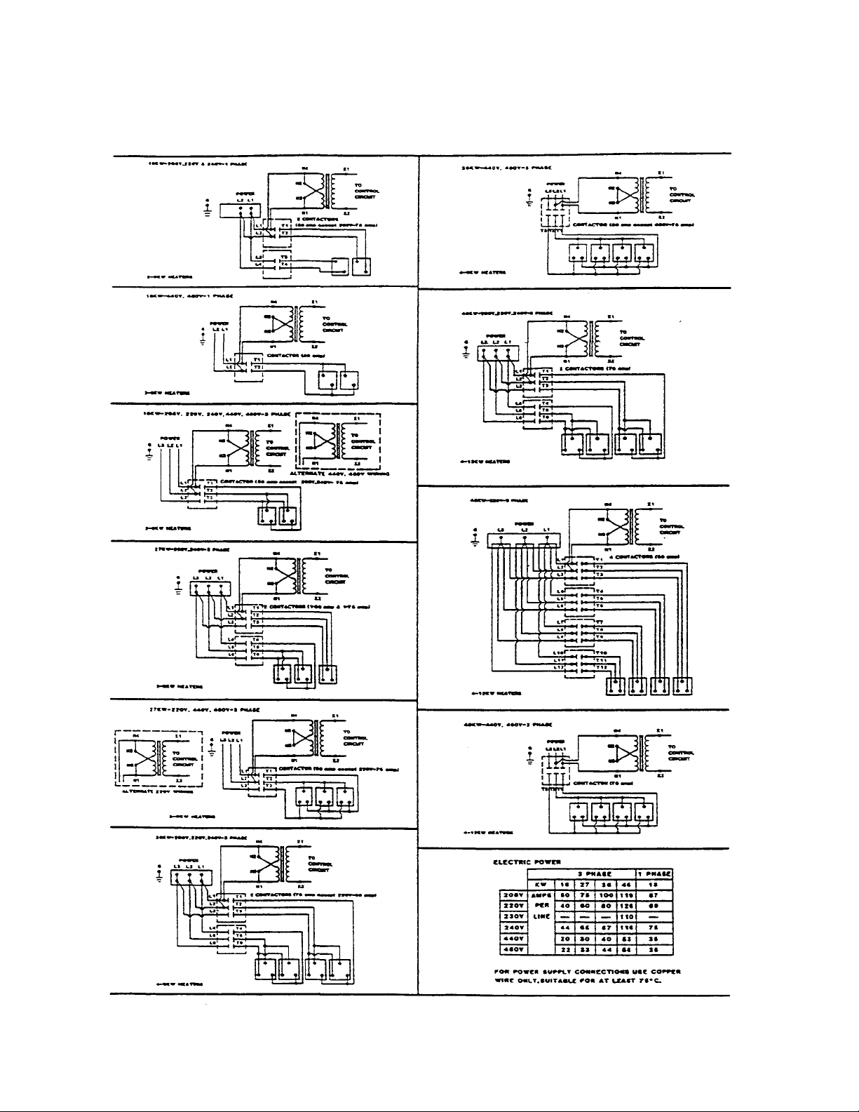
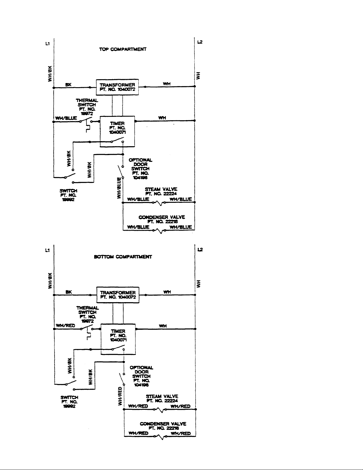
HEATER AND CONTACTOR WIRING SCHEMATICS FOR SOLID
STATE ELECTRIC STEAM GENERATORS
Manufacturer reserves right of design improvement or modification, as warranted.
 Loading...