

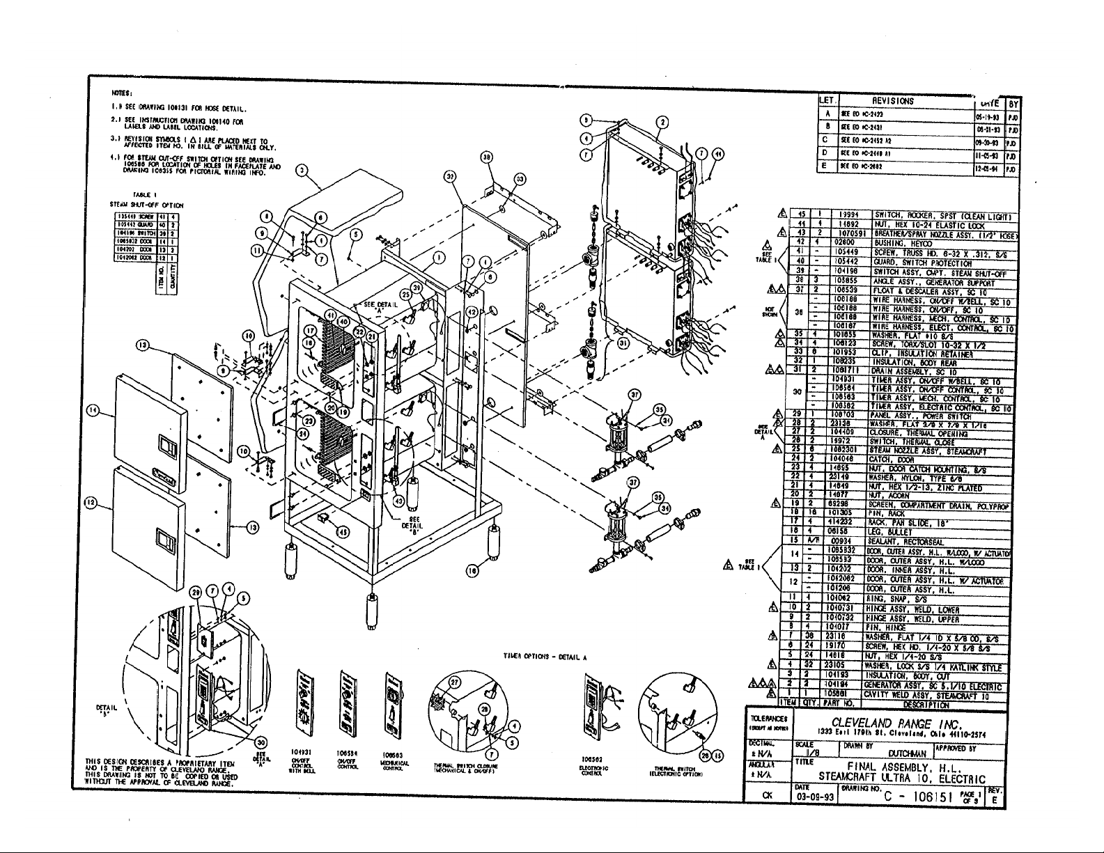
Page 1
Page 2
107314 Door Bumper Kit
107313 Bumper only
Page 3
Page 4
Page 5
Page 6
Page 7
Page 8
Page 9
Page 10
Page 11
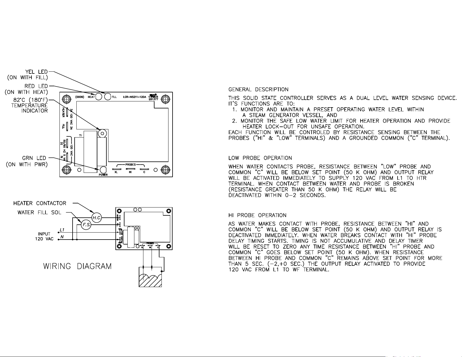
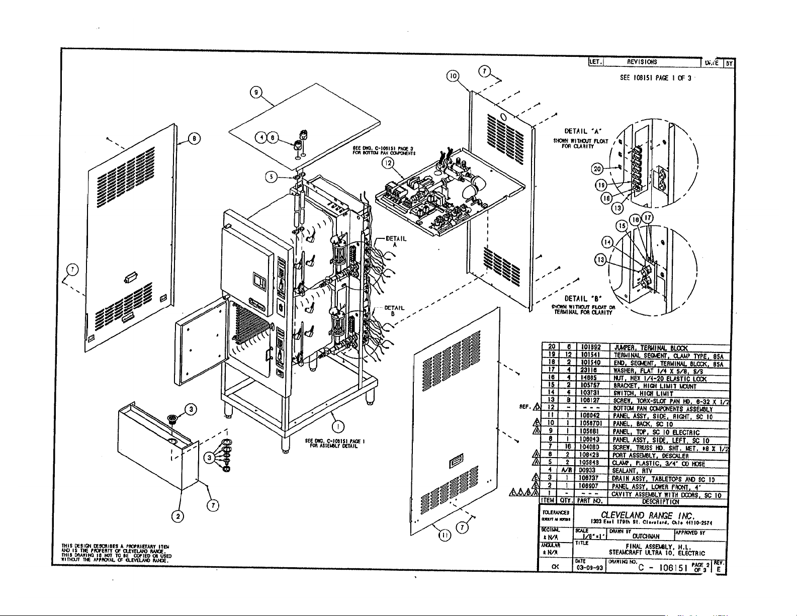
107241 Water Level Board
Page 12
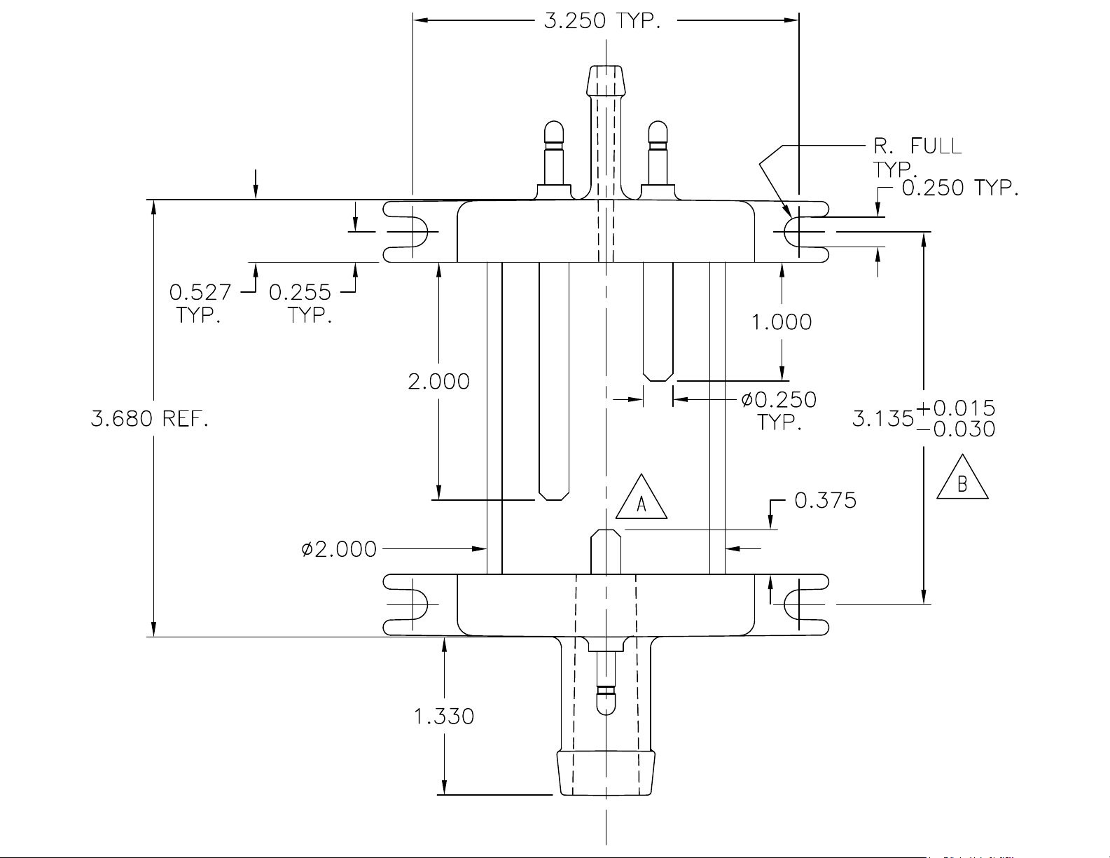
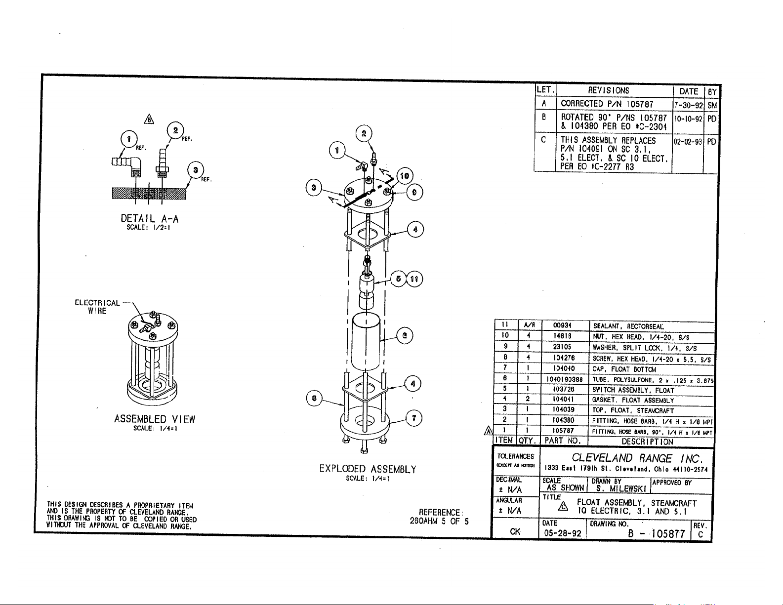
107239 Water Level
Probe Assembly
Page 13
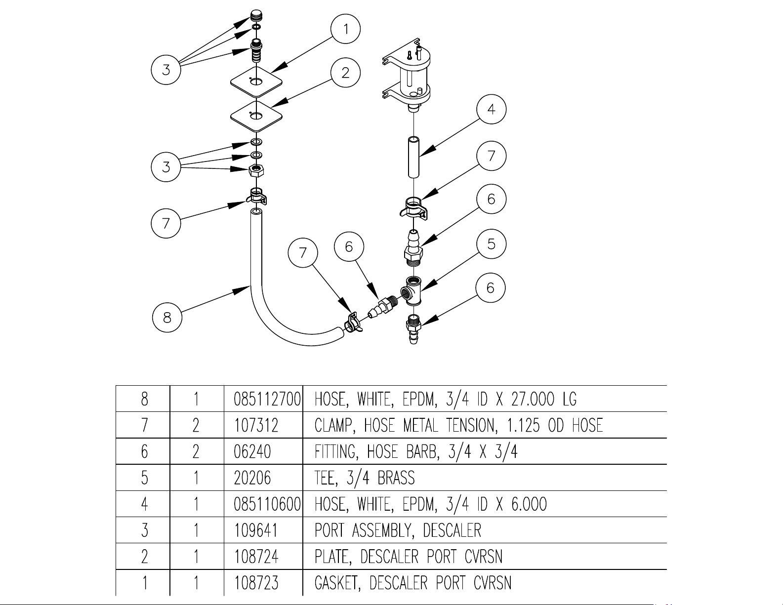
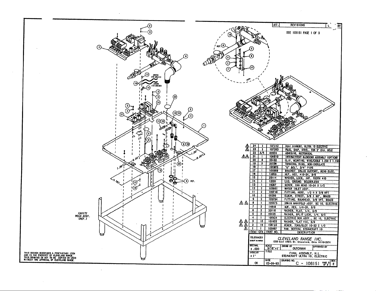
108727
Page 14
Page 15
Page 16
Page 17
Page 18

Page 19

Page 20

Page 21

Page 22

Page 23

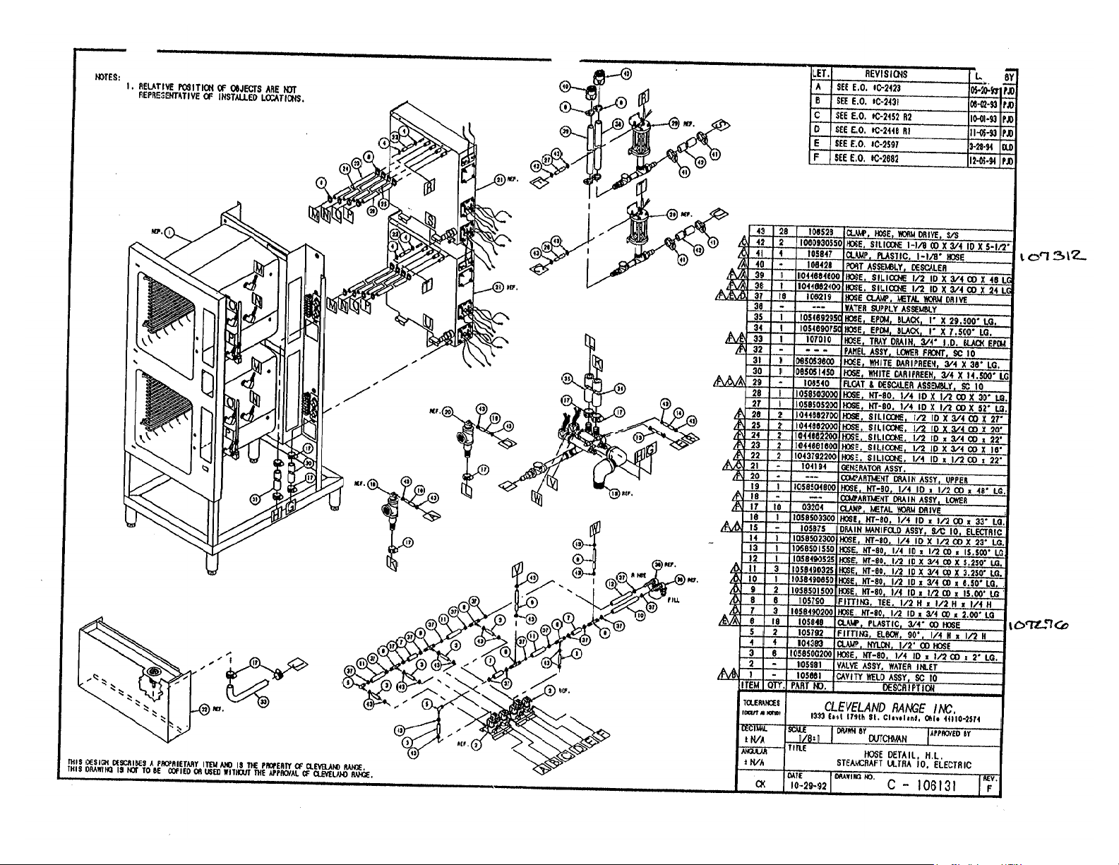
108728 - CLEANING
PORT KIT.
Page 24

Page 25

Page 26

Page 27

Page 28

Page 29

Page 30

Page 31

Page 32

Page 33

Page 34

Page 35

Page 36

Page 37

Page 38

Statement of Responsibilities
This document is for use by experienced and trained Qualified Cleveland Range, LLC Authorized Service
Representatives who are familiar with both the safety procedures, and equipment they service.
Cleveland Range, LLC assumes no liability for any death, injury, equipment damage, or property damage
resulting from use of, improper use of, or failure to use the information contained in this document.
Cleveland Range, LLC has made every effort to provide accurate information in this document, but
cannot guarantee that this document does not contain unintentional errors and omissions.
The information in this document may be subject to technical and technological changes, revisions, or
updates.
Cleveland Range, LLC assumes no liability or responsibility regarding errata, changes, revisions, or
updates.
Qualified Cleveland Range, LLC Authorized Service Representatives are obligated to follow industry
standard safety procedures, including, but not limited to, OSHA regulations, and disconnect / lock out /
tag out procedures for all utilities including steam, and disconnect / lock out / tag out procedures for gas,
electric, and steam powered equipment and / or appliances
All utilities (gas, electric, water and steam) should be turned OFF to the equipment and locked out of
operation according to OSHA approved practices during any servicing of Cleveland Ran ge equipment
Qualified Cleveland Range, LLC Authorized Service Representatives are obligated to maintain up-to-date
knowledge, skills, materials and equipment.
Page 39

Cleveland Range, LLC
1333 East 179th St., Cleveland, Ohio, U.S.A. 44110
Ph: 1-216-481-4900 Fx: 1-216-481-3782 Visit our Web Site at www.clevelandrange.com
Page 40

CLEVELAND RANGE 24CEA10
SEQUENCE OF OPERATIONS
Mechanical Timer
1. Supply power is sent to the primary of the main transformer.
• 115 VAC is sent from the secondary of the main transformer to the on/off rocker,
2. To turn the unit on, depress the red on/off rocker switch.
• 115 VAC is sent to the red indicator light.
• 115 VAC is sent to both coils of the normally open drain valves closing them.
• 115 VAC is sent to the H and N terminals of both water level boards.
3. With the water level board energized and no water in the generators
• After a 5 second delay, 115 VAC is sent from the FILL terminals to the fill solenoids.
• The fill solenoids open and the generators fill through the drain valves until the high
probe is grounded (see step 4).
• The water fills to the low probe in each probe assembly shorting it to ground
• 115 VAC is sent from the HEAT terminals of the water level board to the timed
manual switches.
• 115 VAC is sent to the heat standby timer which will energize the R2 relay coil 3
seconds every 4 minutes
• The normally open contacts of the R2 relay close bypassing the timed/manual switch to
maintain heat while unit is idle
4. For each compartment, when the timed/manual switch is in the manual position or timed
position with time on the timer
• 115 VAC is sent from the timer to the coil of the R5 relay for the top compartment
• The R5 relay energizes
• R5B contacts close sending 115 VAC to the motor timer
• R5A contacts close sending 115 VAC through the optional door switch to the
normally closed contacts of the high limits
• 115 VAC is then sent through the high limits to the coil of condensate solenoid and the
coil of the contactor.
• 115 VAC is sent to the clean light timer.
• When the clean light timer times down 115 VAC is sent to the clean light switch.
• When the clean light switch is depressed the timer is reset.
• When the contactor is energized supply voltage is sent to both of the elements.
• 115 VAC is sent from the timer to the coil of the R6 relay for the bottom compartment
• The R6 relay energizes
• R6B contacts close sending 115 VAC to the motor timer
• R6A contacts close sending 115 VAC through the optional door switch to the
normally closed contacts of the high limits
• 115 VAC is then sent through the high limits to the coil of condensate solenoid and the
coil of the contactor.
Page 41

• 115 VAC is sent to the clean light timer.
• When the clean light timer times down 115 VAC is sent to the clean light switch.
• When the clean light switch is depressed the timer is reset.
• When the contactor is energized supply voltage is sent to both of the elements.
• When the mechanical timer times out 115 VAC is sent to the 3-second timer and then to
the buzzer for 3 seconds.
5. When the water level reaches the high probe then 115 VAC is removed from the FILL
terminal and the fill solenoid is turned off.
6. After the water level drops below the high probe for 5 seconds 115 VAC is sent to the FILL
terminal again.
7. The red 115 VAC switch is depressed and the unit is turned off.
• 115 VAC is removed from the timer and heat circuits.
• 115 VAC is removed from the normally open drain valves allowing the steamer to drain.
• 115 VAC is sent to the 3-minute timer and the R1 relay coil is energized.
• The normally open contacts of the R1 relay will close
• The fill solenoids are then energized for 3 minutes flushing the drains.
Page 42

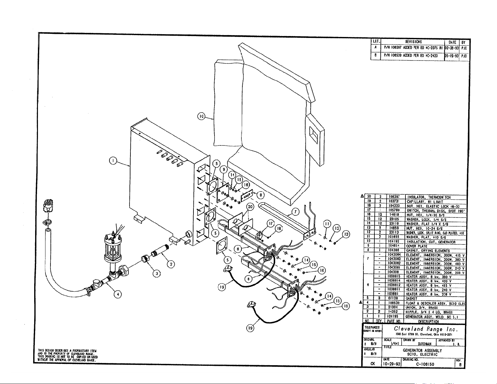
DRYING ELEMENT
STEAMCRAFT-10 ELECTRIC
MECHANICAL TIMER
DRYING ELEMENT
HEATING
ELEMENTS
NOT USED ON
" LOW " WATTAGE MODEL
CUSTOMER
CONNECTION
Ø
3
BLK
DESCALER
TIMERS
3
2
4
1
6
7
8
5
3 MIN TIMER
POWER SWITCH
TIMEDMANUAL
R5B
C
C
NO
MOTOR
NC
UPPER MOTORIZED TIMER
NC
C
MOTOR
NC
C
1
3
TIMEDMANUAL
C
1
3
2
R6B
CNO
NO
NC
2
R3
BLOWDOWN
TIMER
OPTION
LOWER MOTORIZED TIMER
R4
BLOWDOWN
TIMER
OPTION
CONTACTORS
L1
L2
L3
TB
3 2
4
1
7 8
3
2
1
POWER ON
R
MANUAL
NO
C
R5A
NO
R2
MANUAL
C
R6A
NO
R2
1
2
3
HEAT STANDBY TIMER
6
5
R1 COIL
TIMED
R5
DOOR
SWITCH
(SCS OPT)
TIMED
R6
DOOR
SWITCH
(SCS OPT)
R2 COIL
L L
A
NO NO
HEAT
FILL
H
N
XL HI
3 SEC TIMER
3
1
HI LIMIT
SWITCHES
UPPER DRAIN VALVE
HEAT
FILL
H
N
XL HI
3 SEC TIMER
3
1
HI LIMIT
SWITCHES
LOWER DRAIN VALVE
HEATING
ELEMENTS
NOT USED ON
" LOW " WATTAGE MODEL
120V
VALVES
H4
X2
WHT
TO
TO
H1
X1
DESCALE INDICATOR
& RESET SWITCH
R1
WATER FILL
R1
WATER
BOARD
C
BUZZER
2
R3 (TDS OPTION)
COND. VALVE
HEATER CONT.
WATER
BOARD
C
BUZZER
2
R4 (TDS OPTION)
COND. VALVE
HEATER CONT.
PRIMARY
TRANSFORMER
SECONDARY
PROBES
PROBES
L105972 K
Page 43

RED
03509
BLK
LT BLU
NO
9
C
24
R5
ORN/BLK
LT BLU
LT BLU
ORN
BLK
BLK
BLU
LT BLU
BLK
PNK
7
W/BLU
WHT/BLK
W/BLU
WHT/BLK
NC
20
22
321
2
RED
BLK
9
PNK
7
W/BLU
BLK
GRA
WHT/BLK
W/BLU
6
NOC
NC
20
ORN/BLK
WHT
WHT/GRA
WHT
WHT/RED
RED
LT BLU
R6
LT BLU
LT BLU
WHT/BLK
BRN
ORN
BLK
BLK
LT BLU
BRN
BRN
WHT
22
1322
BLK
BLU
RED
REMOVED W / OPTIONAL
RED
DOOR SWITCH ( SCS )
WHT
BRN
24
RED
BLU
REMOVED W / OPTIONAL
DOOR SWITCH ( SCS )
GRA
BRN
YEL
4
YEL
BRN
YEL
WHT/GRA
CUSTOMER CONNECTION
GRA
25
26
15
( TOP ) ( BOT )
BRN
WHT/BRN
WHT
WHT/RED
BLK
BLU
3
BLACK
RED
BLACK
WHITE
RED
WHITE
BLACK
RED
BLACK
WHITE
RED
WHITE
JUMPER SET
FOR 480 VOLTS
H4
1
H2
H3
H1
ALTERNATE TRANSFORMER
CONFIGURATION
JUMPER SET
FOR 208/240 V
H4
H2
H3
H1
FU
FU
20
ORN
R1
BLU
15
WHT
YEL
YEL
WHT/YEL
DRYING
ELEMENT
HEATER
ELEMENT
HEATER
ELEMENT
STEAMCRAFT 10 - ELECTRIC
MECHANICAL TIMER
RED
YEL
BLU
RED
BLU
BLK
WHT
BRN
WHT/GRA
BLK
BLK
BLK
BLK
WHT
BLK
BLACK
RED
BLACK
WHITE
RED
WHITE
BLACK
RED
BLACK
WHITE
RED
WHITE
X1
X2
YEL
RED
WHT/RED
PNK
BLK
X1
X2
WHT
3
WHT/GRA
2
1
GRA
N
RED
WHT/GRA
BLK
RED
5
WHT/YEL
RED
YEL
BRN
WHT/BRN
WHT
WHT/YEL
WHT/YEL
1
10
BRN
RED
4
BLK
YEL
ORN
HEAT
FILL
HN
BLK
17
11
21
XL
YEL
3
2
1
WHT
23
WHT
HEAT
FILL
H N
RED
DRYING
ELEMENT
HEATER
ELEMENT
HEATER
ELEMENT
RED
CHI
RED
WHT/RED
YEL
WHT/YEL
WHT/YEL
YEL
21
XL
YEL
CHI
RED
GRN
BLU
WHT/BRN
ORN
GRN
WHT/RED
8
BRN
18
R3
RED
BLK
R2
20
RED
ORN
BLU
BLU
WHT/BRN
( TOP )
FILL
14
( BOT )
WHT/ORN
WHT/RED
FILL
( TOP )
BRN
COND
BRN
20
R4
YEL
BRN
19
BRN
BRN
WHT/BRN
RED
BRN
RED
18
BLK
BLK
RED
17
YEL
RED
12
RED
RED
WHT
BLK
2
3
4
78
TAN
TAN
12
1
6
5
YEL
YEL
WHT/YEL
WHT/YEL
WHT
2
3
4
87
( BOT )
COND
( TOP )
16
( BOT )
16
BLK
1
6
5
TAN
TAN
NOTE :
THIS ELEMENT NOT
INSTALLED FOR
" LOW " WATTAGE UNIT
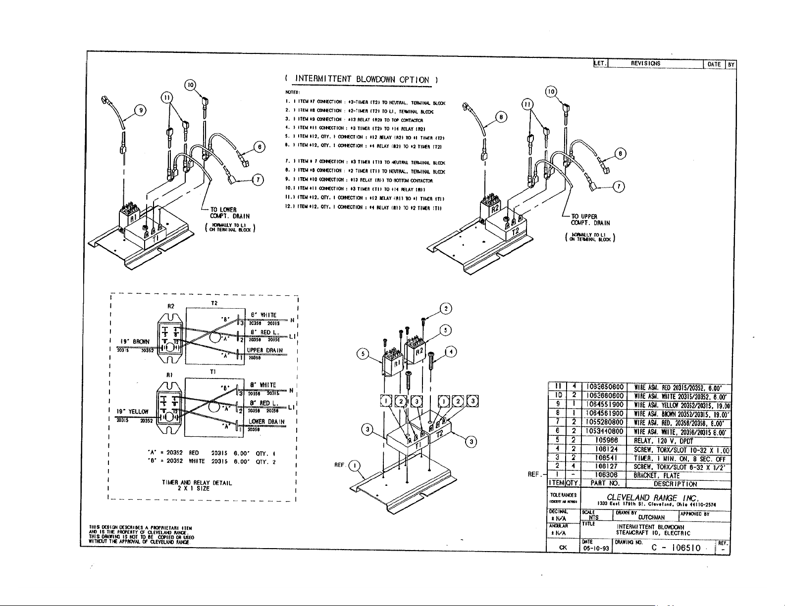
INTERMITTENT
BLOWDOWN OPTION
20535 - TRANSFORMER - POWER
1
2
20477 - 3 SEC TIMER
02193 - TERMINAL BLOCK
3
101541 - TERMINAL SEGMENT
4
106175 - TERMINAL BLOCK 4 POLE
5
19993 - POWER SWITCH
6
104224 - TIMED / MANUAL SWITCH
7
19994 - DESCALE IND RESET SW
8
110198 - MOTORIZED TIMER
9
20478 - 3 MIN TIMER
10
11
109239 - HEAT STANDBY TIMER
12
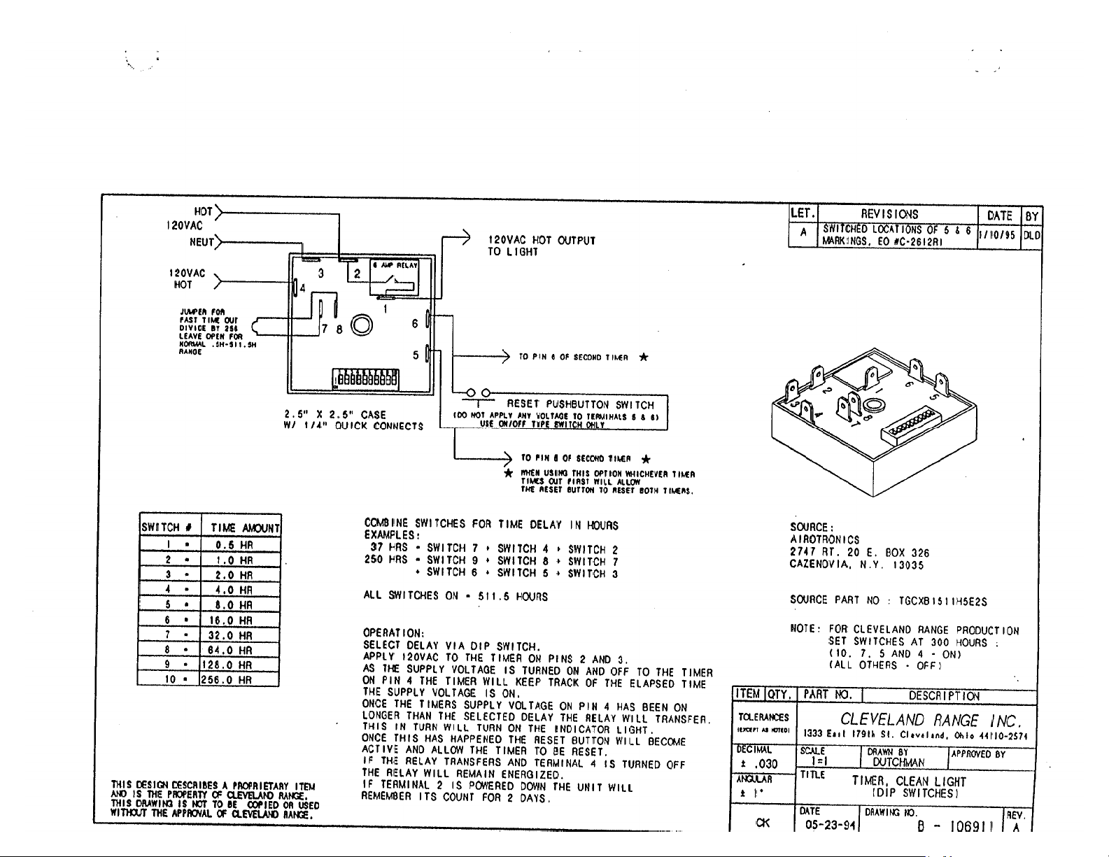
106911 - DESCALE TIMER
13
106541 - INTMT BLOWDOWN TIMER
14
222231 - FILL VALVE
03459 - CONTACTOR ASSY
15
16
22221 - DRAIN VALVE
103731 - HI LIMIT SWITCH
17
18
107239 - PROBE
19
22218 - WATER SOLENOIDS
20
105966 - RELAY
21
107241 - WATER BOARD
22
41350 - BUZZER
23
44168 - TERMINAL BLOCK 2 POLE
24
108880 - DOOR SW ( SCS ) MAG
25
109380 - FUSE 3.5A 600V
26
109374 - FUSE BLOCK
3
13
2
1
3
13
2
1
YEL
2
3
4
1
867
5
PARTS LIST
12
2
3
4
1
87
RED
P105972 K
RED
RED
RED
WHT
RED
6
5
RED
RED
WHT
5
RED
16
16
RED
RED
WHT
RED
RED
RED
WHT
WHT
RED
RED
Page 44

Page 45

Page 46

Page 47

Page 48

PROBLEM:
21CET8
21CET16
21CEA10
Steamer won't
steam.
Steamer won't
steam
Is the red light
on?
Yes
No
Is there supply
voltage to the
primary of the
transformer?
Yes
Supply power to
No
the s t eam er.
Replac e the
water boar d
Replace the wire
from the water
board to the long
probe.
See
STEAMER
WON'T FIL L
Replace the wi r es
to the water
board.
jumper between XL and
C on the water board, i s
No
there 120 VAC between
N and Heat?
No
there debris on
With a
Yes
Is
the Long
probe?
No
No
Is there water
in the sight
Is there 120 VAC
between termi nal s H
and N on th e water
Is there 120 VAC
between ter m i nals
No
N and Heat on t he
water board ?
115 VAC t o th e
common termi n al of
the timed/manual
glass?
Yes
board?
Yes
Yes
Is there
switch?
Replace the wi r es
No
to the switch.
Is there 115 VAC at
the secondary of
the transformer?
Yes
Replace the on/ off
rocker switch
No
Replac e the
transformer.
Yes
Clean or r ep lace
the probe assy.
Yes
Does
the unit steam
in Manual
mode?
Yes
Replac e the
timer.
Does t he
No
st eam er have
the opt i onal
door switch?
steamer steam w i t h
door swit ch
bypassed?
Adjust or replac e
the door switch.
Yes
Does
Yes
Is there
115 VAC t o th e
No
No
high limit?
Is there 115
VAC l eaving
the high limit?
Is there 115
VAC to the coil
of the
contactor?
Is th ere an
amp draw at
the elem en t ?
Wait longer for t h e
steam. Heat fr om t h e
element will heat the
water to steam.
Yes
Yes
Yes
Yes
No
No
No
No
Replac e the
wires to the
high limit.
Replac e the
high limit.
Replac e the
wires to the
contactor coil.
Replac e the
element.
Page 49

PROBLEM:
21CET8
21CET16
24CEA10
Steamer wont
fill
Steamer wont fill.
Yes
Is there supply
voltage to the
steamer?
Yes
No
Supply power to
the s t eam er.
Replace wiri n g t o
the fill solenoid.
Is there water
steamer?
Is there 120 VAC
between the H and N
on the water b oard?
Is there
120 VAC
between Fill and
N on the water
Is there
No
120 VAC across
the coil of the f il l
solenoid?
to the
Yes
Yes
board?
Yes
Yes
Supply cold water
No
Replace the on/ off
No
No
to the s t eamer.
rocker switch.
Remove
the wire from th e H I
terminal on the water
board. Is there 120 VAC
between F i l l
and N?
Yes
Is there
debris on t h e
HI probe in the
probe as sy?
No
Replace the water
No
Replace the wire
to the Hi p r ob e.
board
Replace wiri n g t o
drain valve.
Replace the wir in g
to the intermittent
blowdown timer.
No
No
Replace the f il l
solenoid
Does
the s t eam er have
the opt i onal
intermittent
blowdown timer?
Yes
Is
there 120 VAC
between ter m i nals
2&3 on the timer?
Yes
Replac e the
intermittent
blowdown timer.
No
No
Is
water leaving
the fill
solenoid?
Yes
Is there
120 VAC across
the coil of the
drain valve?
Yes
Is water
draining from
the generator?
Yes
Replace the drain
valve.
If water is l eaving
No
and not draining
from the generator
where is it goin g ?
check for leaks..
Yes
Clean the pr ob es
or replace the
probe as sy.
the fill solenoid
Page 50

PROBLEM:
21CET8, 21CET16, 24CEA10
Electronic timer displays "PAUS" and won't count down
Timer displays "paus"
and won't count down
Is steam heating
Replac e the
thermo-switch
cabinet above 192
degrees (the set
thermo-switch)?
Does the timer
count down when
Yes
the thermo-switch
is bypassed?
the cook i n g
No
temp of the
Yes
No
See
Steamer
won't steam
Replac e the
electronic ti m er
Steam leaks
around the
door
Is COLD water
supplied to both
water lines t o t h e
steamer?
Yes
Is the door gasket
physically
damaged?
Yes
Turn over the
gasket or
replace it.
water(35-60 psi) to
No
Is the door ou t of
No
Supply cold
the s t eam er.
alignment?
Yes
Replac e the
door bearings
and pins.
PROBLEM:
21CET8, 21CET16, 24CEA10
Steam leaks around the door.
Is there 120 VAC
No
Is the drain
obstructed?
Yes
Remove the
obstruction
across the coil of
No
the condensate
Is the solenoid
solenoid?
Yes
opening?
No
No
Replac e the
wiring to the
condensate
solenoid.
Replac e the
condensate
solenoid.
Yes
Replac e the
condensate spray
nozzle
Page 51

PROBLEM:
21CET8
21CET16
24CEA10
Steamer overfills.
(Water sprays into cooking
cabinet)
Steamer overfills
(Water sprays into the
cooking cabinet)
Start
There is an
obstruction in th e
drain. Remove the
obstruction.
Yes
Does
the rise in t h e water
level in the sig h t g l as s
stop when the cooking
cabinet door is
opened?
No
There is an
obstruction in th e
generat or c au sing
it to pressurize.
Delim e the s t eam
generator
thoroughly.
Replace the three
minute timer.
Yes
Yes
Does
the water ri se in the
sight glass when steam
is gener ated an d 0 VAC
to the fill s olenoid?
No
Replace the f il l
solenoid
There is an obstruction in
the plumbing t o and from
the sight glass . Remove
the debris (delime
thoroughly).
Remove the
wire from the Fill
terminal on the water
board. Is there 120 VAC
across the coil of th e
fill
solenoid?
Yes
Yes
Yes
Does
the water level in th e
sight glass stop at th e
HI (short) probe on the
initial fill?
No
Does
water spray in t he
cabinet before t he
water reaches th e H I
(short) probe?
No
Is
there 120 VAC
across the coil of ;t h e
fill solenoid when the
HI (short) probe is
submerged?
Replace the water
level boar d.
Clean or r ep lace
the pr obe
assembly.
Yes
Yes
No
With HI and C
terminals on the
water board ju m ped ,
Is there 120 VAC
between termi nal s N
and Fill?
No
Is
there debris on
the HI (short)
probe?
No
Replace the wire
to the probe
assembly
No
Replace the f il l
solenoid
Page 52

Steamer won't
stop steaming
Is the
timed/manual switch
in the timed posit i on
with no time on the
timer?
Yes
Steamer will steam
constantly in th e
manual position. P u t
No
the timed/manual
switch in the timed
position with no tim e on
PROBLEM:
21CET8
21CET16
24CEA10
Steamer won't stop steaming with
door open
the timer.
Does th e steam er
have the op t ional
door switch?
Yes
Adjust or replac e
the door s w it ch .
No
Does steamer
continue to steam with
both wires removed
from terminal 1 on t h e
heat standby
timer?
No
Replac e the heat
standby timer.
21CET8, 24CEA10
Steamer won't preheat
Yes
120 VAC t o th e
Replace the timer.
Problem:
Steamer
won't
preheat
Is there
coil of the
contacter?
Yes
No
Is
there an am p
draw at t h e
element?
Yes
Replac e the
contactor
voltag e i s rem oved
from t he elemen t
steam is sti l l mad e
No
for approxim ately
10 seconds . This
When supply
is normal.
Is the
timed/manual
switch in t h e t i med p ostion
with time on it or i n t he
manual
postion?
Yes
See Problem:
steamer won't
steam.
This steamer is
not equiped with a
thermostat. The
No
timed manual
switch must be in
manual or time
must be on the
preheat
timer.
Page 53

Page 54

Page 55

Descaling Procedure-SteamCraft Ultra and Gemini Series
How Much DISSOLVE to Use
Model Dissolve
Ultra 3 1/2 Gallon
Ultra 5 1 Gallon
Ultra 10 (Elec.) 1 Gallon (ea.)
Ultra 10 (Gas) 1½ Gallon
Gemini 6 & 10 1 Gallon (ea.)
1. Turn the unit OFF and open the
doors:
This will drain and rinse the generator for about
3 minutes.
2. Turn the unit power back On:
The generator will begin to refill with water.
3. Select Timed with the Timed/Manual
switch:
DO NOT start the timer, since you do not want
to heat the water during descaling. Leave the
doors open.
6. Let the descaler soak in generator for
approximately one hour:
7. After one hour, turn the unit power
This will drain and rinse the generator
Off:
for about 3 minutes.
4.
Remove descaling port cap and add
with the specified amount of
DISSLOVE:
Do this while the unit is refilling. The generators
can take-up to 8 minutes to refill.
After refill has stopped, add extra tap
5.
(See chart above)
water into the descaling port until
liquid is seen entering the cooking
cabinet.
coming out of the drain,
Adding extra water when descaling will raise the
descaling solution higher than the normal fill level,
allowing the DISSOLVE to work on sensors and
surfaces above the water line
Note: Some SteamCraft Ultra models (the
electric powered Ultra 10 and Gemini 6 and 10,
for example) have two generators and two
descaling ports. Both units should be descaled
at the same time, using this procedure
Note: Ultra 10 gas will have liquid
8. After the 3-minute drain cycle
completes, turn the unit back ON. After
the filling has stopped, add water until
liquid enters the cooking compartment (or
drain for the ultra 10 gas), and then turn
the unit OFF. This will drain and flush any
residue from the water level control
assembly. Replace descaling cap.
After the 3 minute drain cycle
9.
completes, Turn the unit ON and set
the Timer for 20 minutes:
Time/Manual switch is in the timed setting
and the doors are closed.
Make sure the
10. When the timer times out (after 20
minutes) turn the power Off:
This will drain and rinse the generator for
about 3 minutes.
This ends the descaling procedure. You can
now turn the unit back on and resume normal
startup and cooking operations.
 Loading...