

Cleveland 24-CET-1 Service Manual
Cleveland Range
SERVICE
Printed
5/93
®
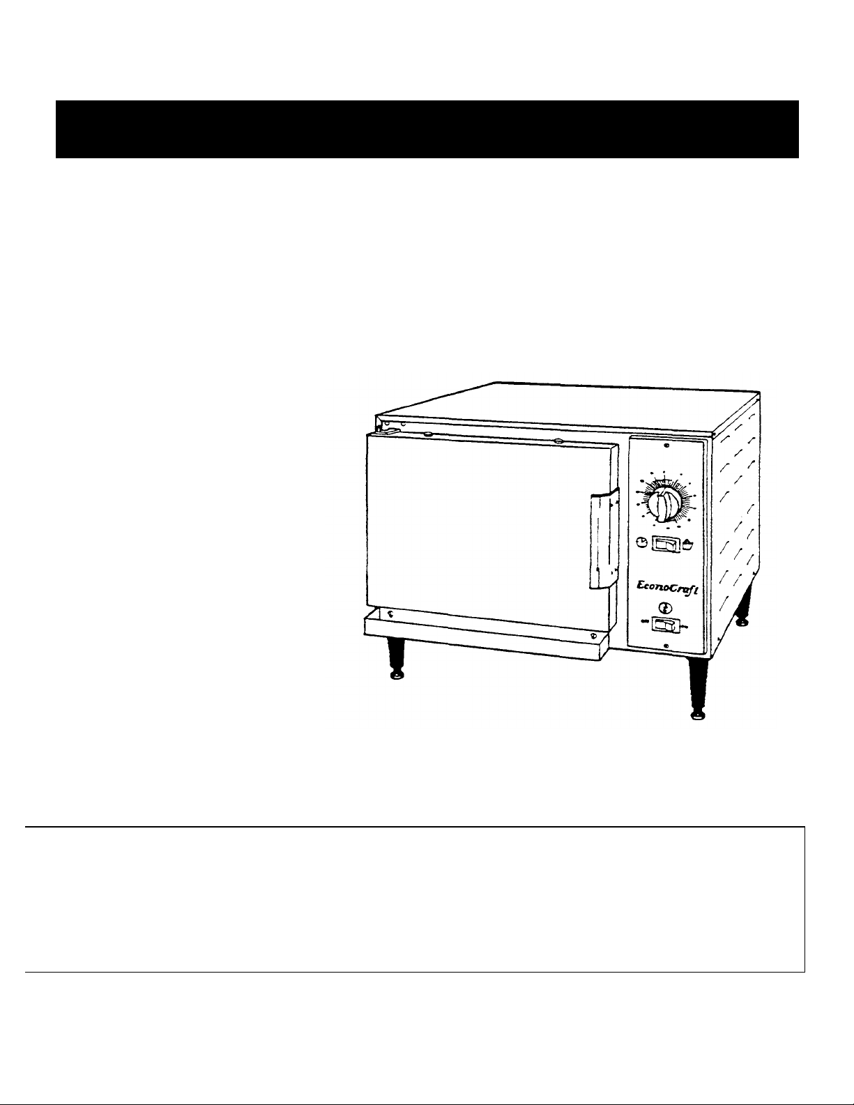
EconoCraft
Counter Type
Convection Steamer
MANUAL
MODEL 24-CET-1
Cleveland Range, Inc.
UNITED STATES CANADA
1333 East 179
Phone: (216) 481-4900 Telex: 98-0546 1177 Kamzto Road
FAX: (216) 481-3782 Mississaugha, Ontario, Canada L4W1X4
Phone: (416) 624-0260 FAX: (416) 624-0623
th
St. Cleveland, Ohio 44110 Garland commercial Ranges
CTS-06

PROTECTING WARRANTY COVERAGE
REFERENCE
Water Quality Requirements and Analysis
.,
7
Steam Generator Maintenance and Maintenance Records
31
Daily Draining and Washout
31
Descaling Frequency and Procedure
32
Approved Chemical Cleaners
32-33
Authorized Maintenance and Repair
35 Unvented Drain
11
Blocked Drain
33
Wate
r Pressure
16
The warranty printed to the left specifies the owner/user's responsibility for proper
installation, operation, and maintenance of the EconoCraft - If these responsibilities arc
not met, the Limited Warranty and/or Extended Limited Warranty coverage may be
adversely affected. The following table is provided to assist the owner/user in meeting
these responsibilities. In addition, the warranty advantages of installing a SteamerGard
water treatment system are explained after the table.
The Warranty Protection Table lists installation, operation, and maintenance factors
that have in the past adversely affected warranty coverage. The owner/user of an
EconoCraft should pay particular attention to these factors to protect his warranty
coverage. This table is not a comprehensive list of the owner/user's responsibilities.
Cleveland Range steam products are intended for use only by professionally trained
personnel- To meet his responsibilities, the owner/user must supplement this guide
with any additional actions consistent with the operation of steam generating food
preparation equipment by a trained professional.
Warranty Protection Table
PAGE
SUBJECT
Electric Power Requirements 7
SteamerGard Water Treatment System
A SteamerGard water treatment system protects the EconoCraft from impurities contained in regular tap water, especially Total Dissolved Solids (TDS) which cause lime
and scale deposits in steamer equipment. "The protection is so effective that
Cleveland Range increases the warranty coverage on an EconoCraft installed in
conjunction with a SteamerGard system to five years for pans and three years for
labor on water related components, elements, valves, generators, piping, etc.
However, even with a SteamerGard system installed, me owner/user should follow the
guidance of me Warranty Protection Table.

Table of Contents
Chapter Page
CHAPTER 1. PRODUCT IDENTIFICATION 1
MODELNUMBER 1
SERIAL NUMBER 1
PRODUCT INFORMATION PLATE. 1
CHAPTER 2. INSTALLATION INSTRUCTIONS 3
INTRODUCTION. 3
INSTALLATION POLICIES 3
INSTALLATION OVERVIEW 4
PREPARATION ATION FOR INSTALLATION 5
Unpacking and Inspection 5
Shipping Damage Instructions 6
Electric Power Requirements 7
Water Quality Requirements 7
Softened, Treated, or Filtered Water 8
Select the Operating Location 8
INSTALLATION INSTRUCTIONS 10
Assembly 10
Install Four Legs 11
Position and Level EconoCraft 11
InstalI and Connect the Free Air Vented Drain Lines
Install Electric Power Lines
Connect Electrical Line 14
Canadian Wiling Considerations 15
Install Water Supply Lines 15
Connect Water Supply Lines 17
Single Untreated Water Connection 17
Double Water Connection With Preheater 17
Double Water Connection With SteamerGard 18
Testing Water Supply Lines 18
Final Setup And Checkout 19
Setup 19
MANUAL Test 19
TIMED Test 20
Condenser Flow Adjustment 21
CHAPTER 3. OPERATION 23
INTRODUCTION 23
OPERATIONAL SAFETY 23
CONTROL PANEL
DRAIN PLUG 24
MANUAL MODE 25
11
13
24
Page i

Page ii
Table of Contents (continued)
Chapter Page
TIMED MODE 25
STARTUP AND PREHEAT 26
COOKING 26
TIMED Cooking 27
MANUAL Cooking 27
DRAIN STEAM GENERATOR (Every 4 hours) 28
SHUT DOWN (At end of day or shift) 28
CHAPTER 4. PREVENTATTVE MAINTENANCE AND TROUBLESHOOTING 31
INTRODUCTION 31
MAINTENANCE RECORDS 31
DAILY MAINTENANCE 31
Clean EconoCraft 31
WEEKLY MAINTENANCE 31
Descale Steam Generator 32
YEARLY MAINTENANCE 33
TROUBLESHOOTING GUIDE 34
TROUBLESHOOTING NOTES 35
TROUBLESHOOTING QUICK TEST 36
CHAPTER 5. ELECTRICAL SYSTEM 37
INTRODUCTION 37
Figures and Illustrations 37
ECONOCRAFT ELECTRICAL CIRCUITS 37
High Voltage Circuit 37
120 VAC Circuit 37
Low Voltage Control Circuit 39
Timer Circuits 39
CIRCUIT OPERATION 39
MANUAL Mode Circuit Operation 39
TIMED Mode. Circuit Operation 40
ELECTRICAL, CIRCUIT COMPONENTS 41
Terminal Block 41
Heater Element 41
ON/OFF Switch 42
TIMED/MANUAL Switch 42
Fill Solenoid Valve 42
Condenser Solenoid Valve 43
Mechanical Timer 43
3-Second Timer and Buzzer 44
High Temperature Limit Switch 44

Page ii
Chapter
Table of Contents (continued)
Page
Water Level Control Unit 44
Water Level Probe Assembly
Low Level Probe 45
High Level Probe 45
COMPONENT TESTING GUIDE INTRODUCTION 46
Nominal Voltage 46
FUNDAMENTAL COMPONENT TESTING 46
Visual Check 47
Connection Points and Wiring 47
Solenoid Valves 47
Timers 48
Thermostatic Snap 48
Terminal Block 48
Heater Element 49
Resistance Measurements 49
Insulation Resistance Measurements 49
Voltage Measurements 50
COMPONENT TEST PROCEDURES 50
Initial conditions for all testing 50
CT:1 ON/OFF Switch 50
CT:2 Fill Solenoid Valve 51
CT:3 Condenser Solenoid Valve 52
CT -4 TIMED/MANUAL Switch 53
CT5 High Temperarure Limit Switch 54
CT:6 Mechanical Dial Tuner 55
CT -7 Heater Contactor 55
45
CT-8 Heater Elements 56
CT-9 Water Level Control Unit 5S
CT-10 3-Second Timer and Buzzer 59
CT:11 Low Level Probe
CT:12 High Level Probe
CT:13 Transformer
CHAPTER 6. ILLUSTRATED PARTS LISTS 63
INTRODUCTION
Parts Differences Among Econocraft Steamers
Electrical Wiring and Schematic Ladder Diagrams
Ordering Parts 63
60
60
61
63
63
63
EconoCraft Service Manual, Chapter 1
Page 0
MODEL NUMBER
SERIAL NUMBER
Page 1
CHAPTER 1. PRODUCT IDENTIFICATION
Cleveland Range, Inc. identifies products by two numbers: a model number and a
serial number. The model number identifies the product characteristics. The serial
number identifies the individual unit.
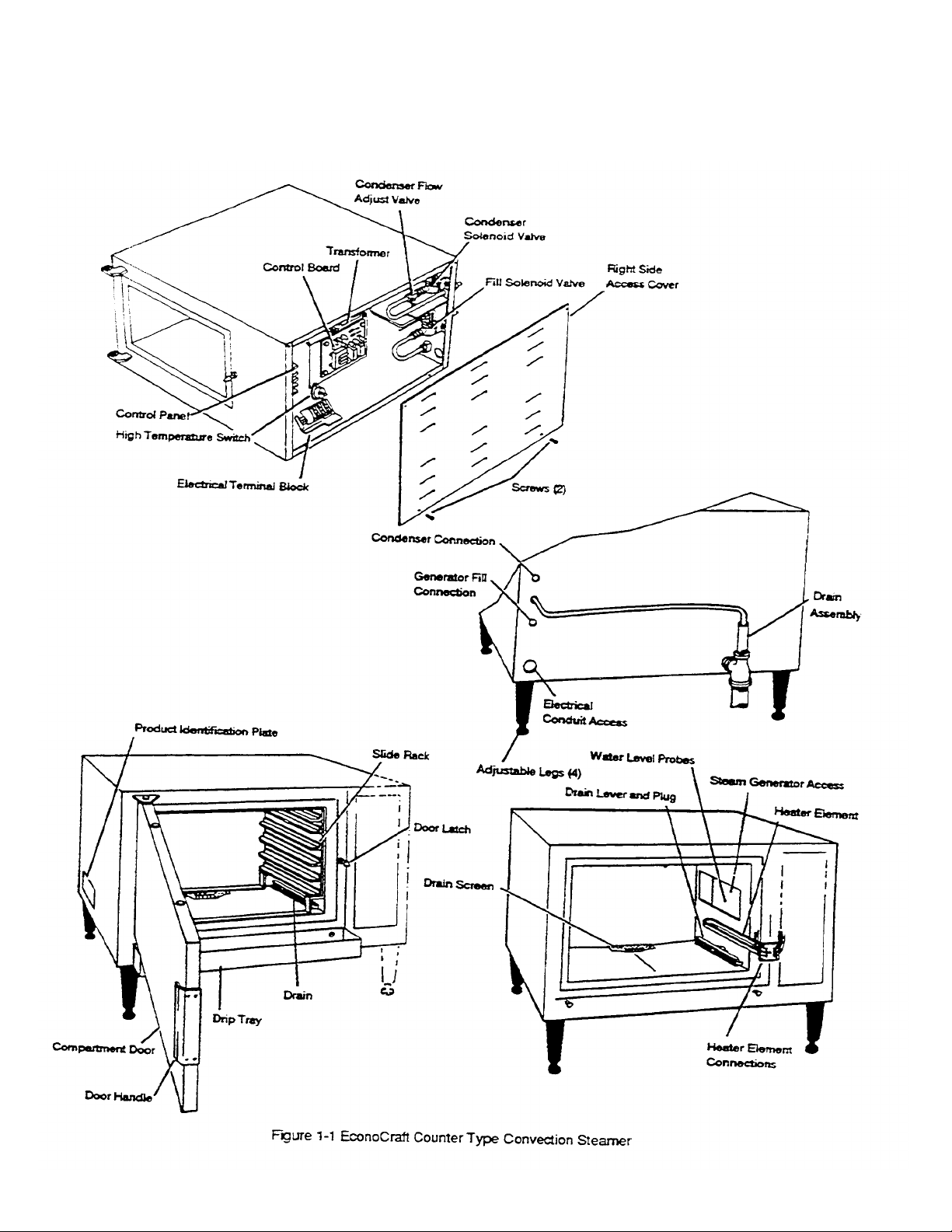
EconoCraft steamers are identified by model number 24-CET-l. Each character of
the model number identifies a characteristic of the steamer. The EconoCraft is a
Convection steamer, .Electric powered,and Table-mounted with an input energy
rating of 8 kW. This manual covers all standard features of model 24-CET-l
EconoCraft steamers. Figure 1-1 illustrates the Econo-Craft and identifies the
major components.
During manufacture, EconoCrafts are assigned serial numbers. A typical
EconoCraft serial number is WC -7350-90G-02. The left half of the number carries
design information- The right half of the number contains the manufacturing date
and the unit of the manufacturing lot. The date of our sample number is 90G -02:
90=1990, G=July. 02=the second unit of the manufacturing lot. Serial numbers are
used when explaining differences in design, parts, or operation among units with
the same model number. For example: a particular part may be used on all 24CET-l steamers with serial numbers before WC -7350-90G-02, and a different pan
used on 24-CET-l steamer WC-7350-90G-02 and all those manufactured after it.
PRODUCT INFORMATION PLATE
Presently, there are no significant design, parts, or operating differences among
model 24-CET-l EconoCraft steamers.
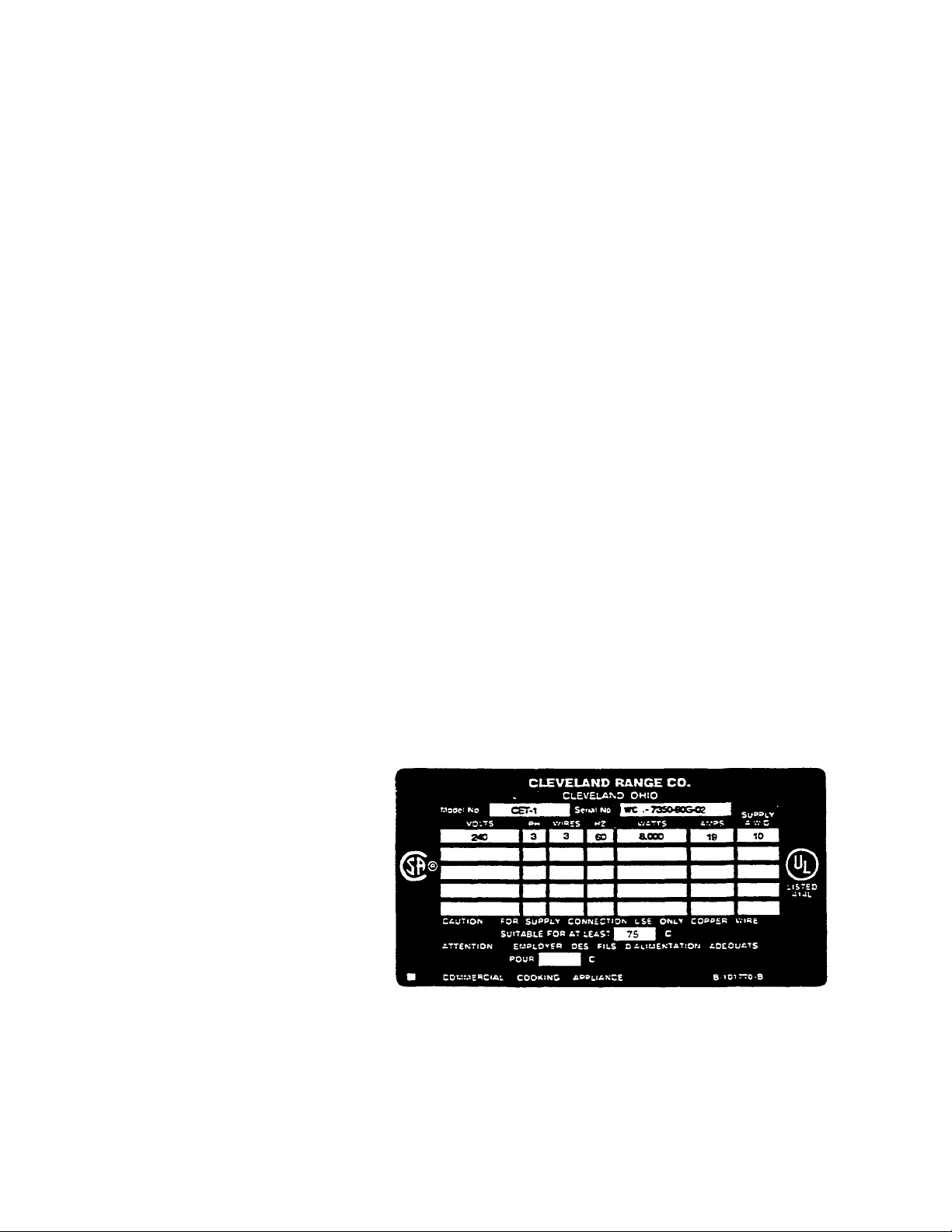
The Product Information Plate on the left side of me unit lists me model number
and serial number for the steamer. Refer to Figure 1-1 for the location of the plate.
Figure 1-2 illustrates a typical EconoCraft product information plate. The plate
also lists power and wiring requirements.
Figure 1-2. EconoCraft Product Information Plate
Cleveland Range, Inc. Printed 5/93

Page 2 EconoCraft Service Manual, Chapter 1 Model 24-CET-1
WARNING
DEATH, INJURY, AND EQUIPMENT DAMAGE
could result from improper installation of the
EconoCraft, or from installation of a unit damaged
during shipment or storage. Either of these conditions could also void the equipment warranty.
DO NOT INSTALL an EconoCraft suspected of
damage.
Install the EconoCraft according to the policies and
procedures outlined in this manual.
Printed 5/93 Cleveland Range. Inc.

Model 24-CET-1 EconoCraft Service Manual, Chapter 2 Page 3
CHAPTER 2. INSTALLATION INSTRUCTIONS
INTRODUCTION
This chapter is a guide for qualified, professional plumbers and electricians
installing the EconoCraft steamer. This guide does not include procedures and
precautions in the common domain of licensed plumbers and electricians, or
experienced food service equipment installers. The instructions in this chapter
must be used in conjunction with a thorough understanding of the Basic Plumbing
Code of the Building Officials and Code Administrators International, Inc.
(BOCA) and the Food Service Sanitation Manual of the Food and Drug
Administration (FDA).
Before starting installation, the owner and the installer should read through this
chapter and thoroughl y understand and agree upon:
• The installation policies of Cleveland Range, Inc. as stated in Installation
Policies-
• An installation plan based on Installation Overview and Preparation For
Installation.
• Responsibility for feed water quality and its testing as described in
Preparation For Installation, Water Quality.
INSTALLATION POLICIES
• The EconoCraft must be installed by qualified plumbing and electrical
personnel, working to an applicable national and local codes. Equipment
installation must compl y with the Basic Plumbing Code of me Building
Officials and Code Administrators International, Inc. (BOCA) and the Food
Service Sanitation Manual of the Food and Drug Administration (FDA).
• Cleveland Range designs and manufactures equipment to comply with
applicable standards for manufacturers. Included among those certification
agencies which have approved the safety of the equipment design and
construction are: UL, A.G.A., ASME/N.Bd-, NSF, CSA, CGA, ETL. and
others.
• This equipment is designed and certi fied for safe operation only when
permanently installed in accordance with local and/or national codes. Many
local codes exist, and it is the responsibility of the owner and installer to
comply with these codes.
• In no event shall the manufacturer assume any liability for damage or injury
resulting from installations which are not in strict compliance with the
installation instructions and the codes cited above. Specifically, the
manufacturer will not assume any liability for damage or injury resulting from
improper installation of equipment, including, but not limited to, temporary or
mobile installations.
Cleveland Range, tnc. Printed 5/93
Page 4 EconoCraft Service Manual, Chapter 2 Model 24-CET-1
Figure 2-1. Schematic Installation Diagram
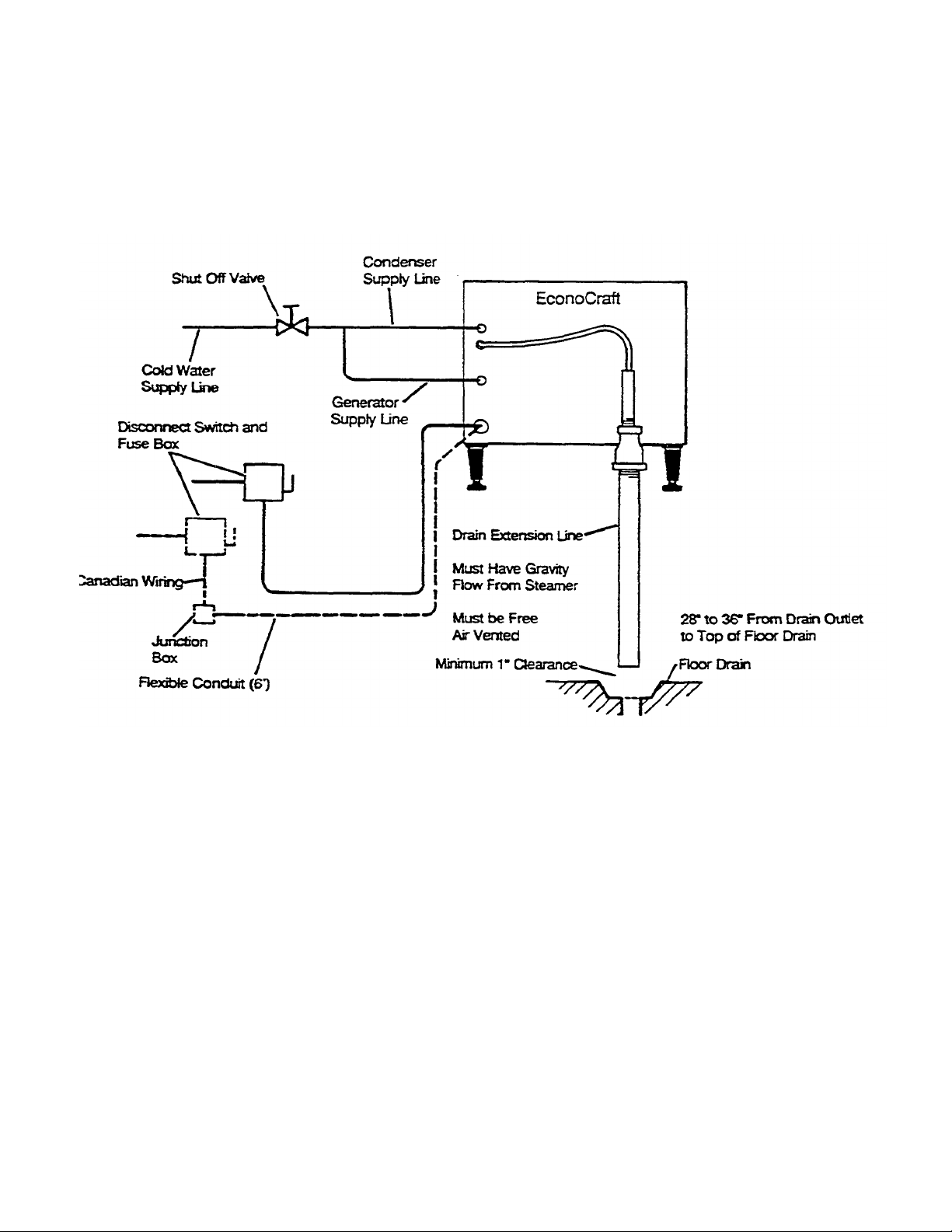
INSTALLATION OVERVIEW
Schematic Installation Diagram, Figure 2-1, illustrates the various electrical,
water, and drain lines that must be connected to the EconoCraft. These lines
can be constructed and connected to the EconoCraft easily and without
delays, if the various construction and installation tasks are performed in a
planned sequence. Table 2-1 summarizes these tasks and lists them in a
recommended sequence. The Installation Check List outlines the overall
installation process; the instructions referenced in Table 2-1 provide details.
Installation requirements may vary from site to site; adapt the check list
accordingly.
Printed 5/93. Cleveland Range, Inc.
Model 24-CET-1 EconoCraft Service Manual, Chapter 2 Page 5
Test EconoCraft water supply.
6
Assemble parts shipped loose.
6
Table 2-1. Installation Check List
TASK PAGE REFERENCE
Preparation
Select water supply system. 6
Install water treatment system. 6
Select EconoCraft location. 8
Installation
Unpack and inspect EconoCrafi. 5
Position and level EconoCraft. 11
Install drain line. 11
Connect drain line. 11
Install electric power line. 13
Connect electrical line. 14
Install water supply lines. 15
Connect water lines. 17
Perform final setup and checkout 19
PREPARATION FOR INSTALLATION
Select and prepare the EconoCraft operating location before permanently
positioning the unit Protect the unit and packaged components during site.
preparation. Do not select me operating location or start installation before
checking the electric power, gas, and water quality requirements to assure proper
drainage, ventilation, and safety.
COMPLETED
Unpacking and Inspection
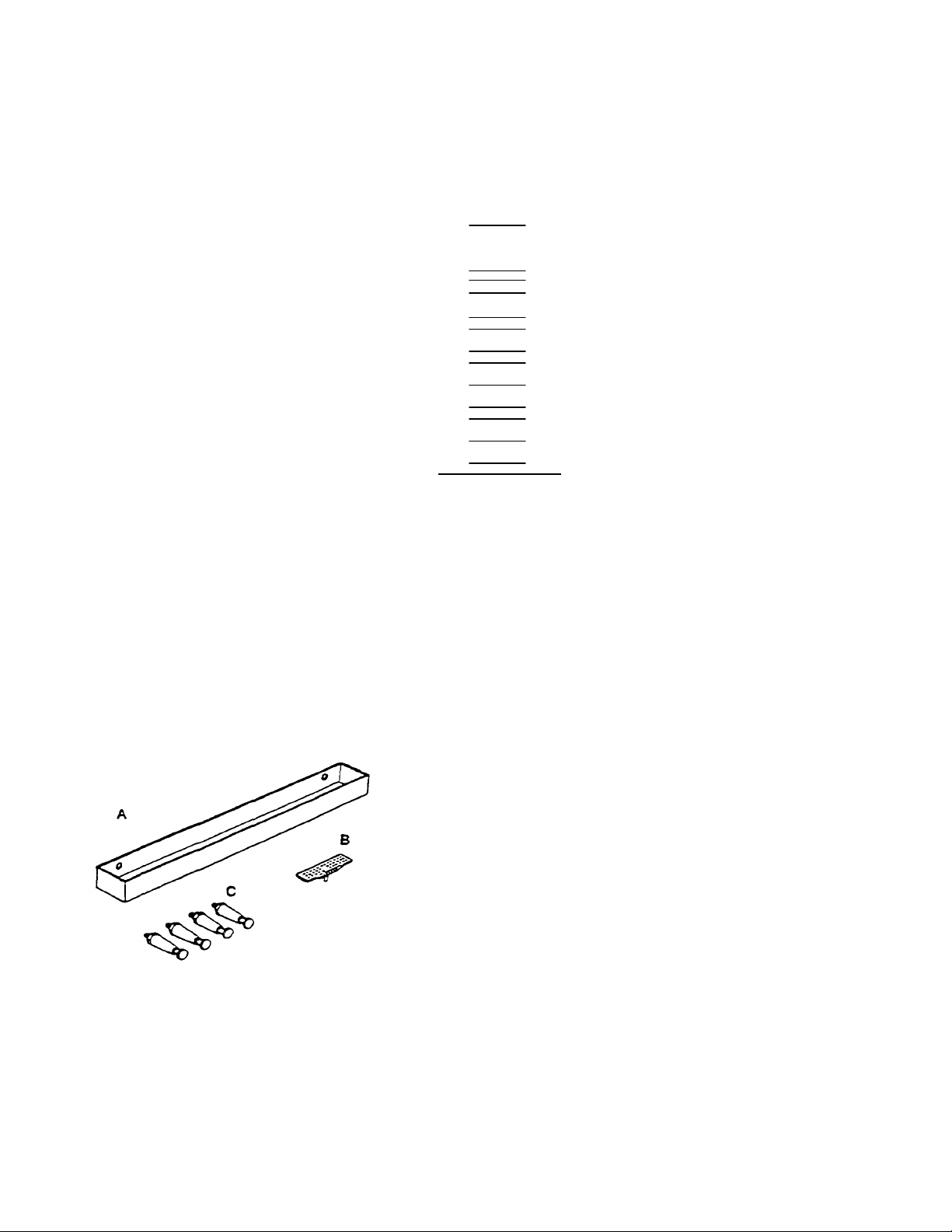
Figure 2-2- Parts Package Components
Cleveland Range, Inc- Pnnted5/93
1. Before unpacking the shipping canon, visually inspect it for damage.
• If the shipping canon appears damaged, do not open the carton- Refer to the
Shipping Damage Instructions below.
• If the sh ipping carton is undamaged, open it and remove the EconoCraft-
2. Slit the four comers of the canon and peel canon sides away from the
EconoCraft.
3. Open me door of the EconoCraft, and remove the package of pans. The
package contains six pans as illustrated in Figure 2-2. Check that all pans
nave been included in the package.
A Drip Tray B Drain
Screen C 4 Legs
Page 6 EconoCraft Service Manual, Chapter 2 Model 24-CET-1
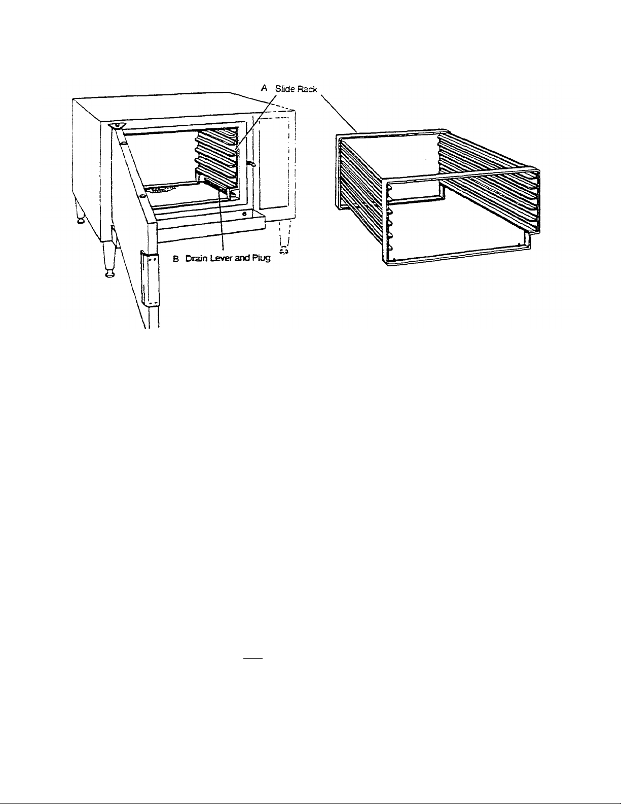
Figure 2-3. Pre-assembled Parts
4. When the parts package is removed, several pre-assembled pans can be
seen inside the unit Refer to Figure 2-3. Do not remove or try to operate
these parts at this time.
A Pan Rack
B Drain Plug and Lever
5. Inspect the EconoCraft and pans for damage or loss.
• If you discover or suspect shipping damage or loss, refer to the Shipping
Damage Instructions below.
• If all items are accounted for and undamaged, proceed to Assembly and
install the unassembled pans listed in step 3-
Shipping Damage Instructions
If shipping damage to the EconoCraft is discovered or suspected, observe the
following guidelines in preparing a shipping damage claim.
• Write down a descript ion of the damage or the reason for suspecting
damage as soon as it is discovered. This will help in filling out the claim
forms later.
• As soon as damage is discovered or suspected, notify the carrier that
delivered the shipment.
• Arrange for carrier representative to examine damage.
• Fill out all appropriate claim forms and have the examining carrier sign and
date each form.
Printed 5/93 Cleveland Range, Inc.

Model24-CET-1 EconoCraft Service Manual, Chapter 2 Page 7
Electric Power Requirements
The characteristics of the electric power supply must match the power
requirements specified on the EconoCraft Product Information Plate. The plate is
located on the left side of the unit.
Water Quality Requirements
As with any steam generating equipment, poor water quality degrades EconoCraft
performance. If feed water is low in Total Dissolved Solids (TDS) and free of
paniculate matter, the steam generator, hearing element, and valves of the
EconoCraft will give years of trouble-free service with a minimum of
maintenance.
In some areas, even potable tap water contains a variety of impurities that can
cause costly problems in steam generating equipment. Of primary concern are
mineral salts and other impurities which remain behind as lime or scale deposits
during the steam generating process. These deposits have caused many
components to fail. including heating elements, probes, and solenoid valves. Of
equal importance, lime and scale deposits decrease the efficiency of heat transfer
which causes increased water and power consumption. EconoCraft use in areas
with poor water quality requires installation of a SteamerGard water treatment
system or increased frequency of maintenance, cleaning, and descaling.
Check the quality of feed water before starting construction of the water supply
lines. If a SteamerGard water treatment system must be installed 10 achieve
acceptable water quality, install it before running the water supply lines to the
EconoCraft.
Contact a local water treatment specialist for an on-the-premises water analysis.
The recommended minimum feed water quality requirements for the EconoCraft
are listed in Table 2-2.
• If analysis shows that the supply water is within me required limits, a single
water connection can be installed as illustrated in Figure 2-13.
• If analysis shows the supply water within required limits and a hot water heater
is desired for preheating water to the steamer, install as illustrated in Figure 2-
14. DO NOT install with hot water to the condenser inlet. The condenser
supply must be cold water for proper operation of the steamer.
• If analysis shows that the supply water is NOT within the required limits, a
SteamerGard water treatment syst em and two water supply lines must be
installed as illustrated in Figure 2-15.
• If analysis shows that the supply water is NOT within the required limits, and it
is not possible to install a SteamerGard water treatment; plan on increasing the
frequency of maintenance, cleaning, and descaling beyond that recommended
in the maintenance schedule (Chapter 4, page 31).
• Always connect a cold water supply to the EconoCraft water supply lines. DO
NOT USE HOT WATER. The steamer will not function properly or withi n
design safety limits if hot or warm water is supplied to either the condenser
connection or the steam generator fill connection.
Cleveland Range, Inc- Printed5/93
Page 8 EconoCraft Service Manual, Chapter 2 Model 24-CET-1
Table
2-2.
Minimum Feed Water Quality Requirements
Total Dissolved Solids less than 60 parts per million
Silica less than 13 parts per million
Alkalinity less than 20 parts per million
ph factor greater than 7-5
Softened, Treated, or Filtered Water
Do not use softened or chlorinated water in the EconoCraft steam generator.
If the water supply is treated or softened either by the water company or on
the premises, it may contain chlorine or various salts. These additives are
damaging to the EconoCraft steam generator. Salts used to soften water
cause rapid scale buildup, and increased corrosion.
Some water treatment plants kill bacteria in the water by adding chlorine.
Chlorinated water is actually dilute hydrochloric acid. It is very damaging to
the EconoCraft. When healed in the steam generator, chlorinated water
rapidly dissolves generator walls and heater elements. In extreme cases,
poisonous and highly corrosive chlorine gas is released in the steam generator.
Installing a high volume, charcoal or reverse osmosis, water filtering system
removes most of me salts and chlorides introduced by water treatment and
softening. Contact a local water treatment specialist or the local water
company for assistance with chlorinated water.
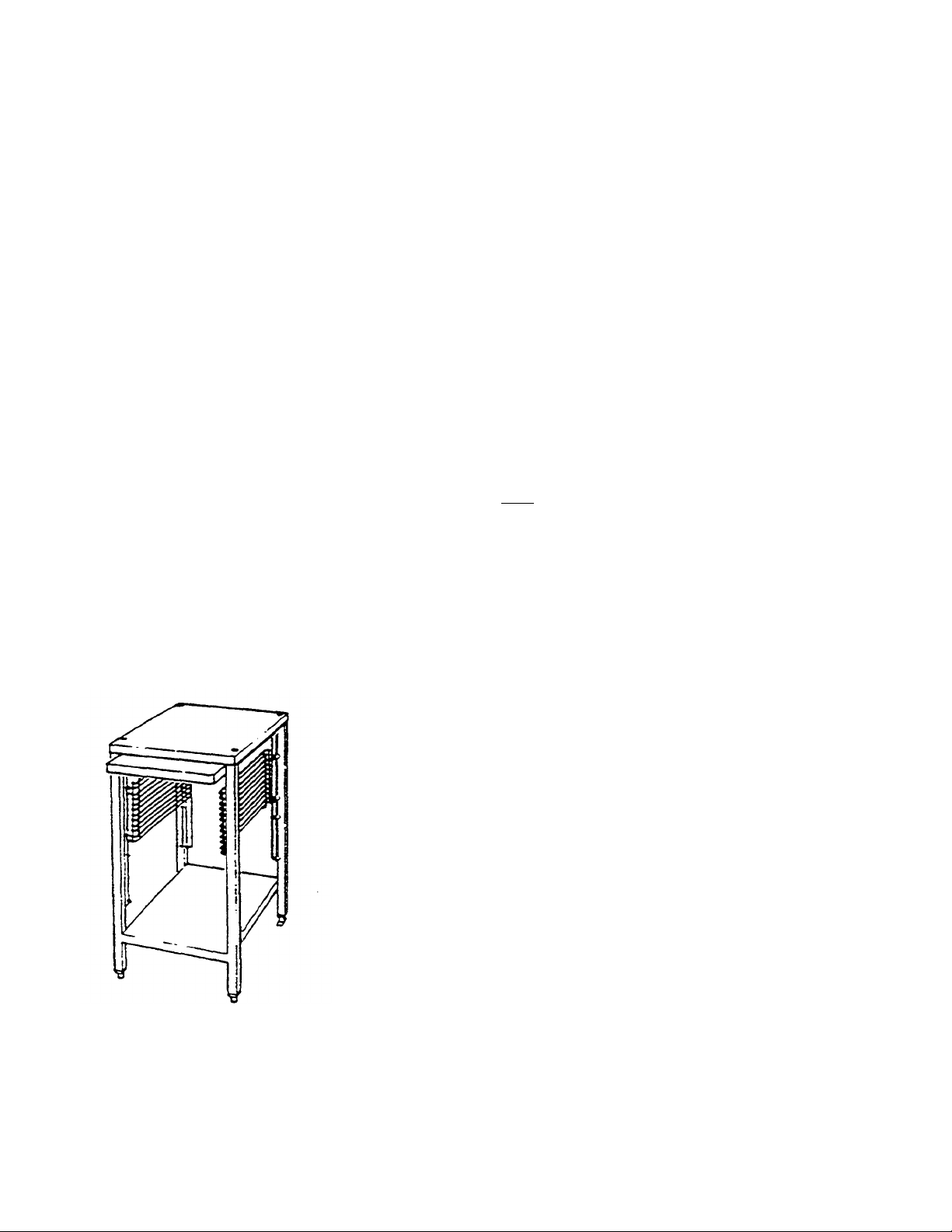
Figure 2-4. Equipment Stand
When selecting an operating location for the EconoCraft, observe me following criteria.
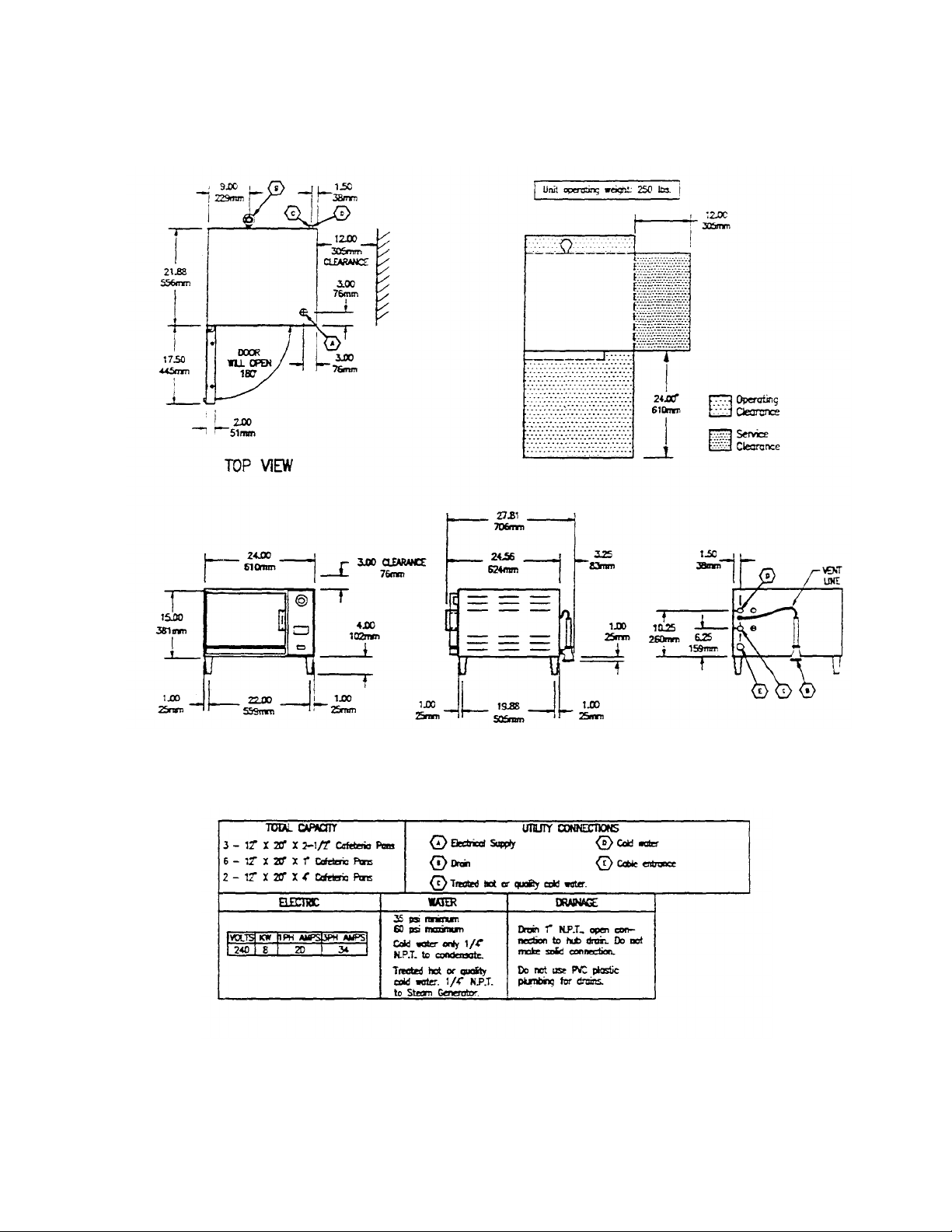
• The EconoCraft uses a minimum of counter space. Figure 2-5 illustrates
the dimensions and clearances required. The 3-inch clearance at the rear
includes spacing for the water inlet and fittings, and the maximum size (11/4-inch NPT) drain fittings.
• Note in Figure 2-5 that a 3-inch clearance is required above the
EconoCraft. Do not store articles on top of the unit.
• The EconoCraft weighs approximately 100 pounds. The counter area
selected must be capable of supporting an operational weight of
approximately 120 pounds to include the weight of wat er and food.
• The EconoCraft has capacity for one 12"x20" x25" Cafeteria Pan (model #
SP-2.5 or PP-2.5). Convenient storage for pans should be considered
when selecting the operating location.
If a satisfactory counter location is not available, consider using a model ES2424 Equipment Stand. This stand, illustrated in Figure 2-4, is designed to
support the EconoCraft, and meets the above criteria-
Printed 5/93 Cleveland Range, Inc.
Model 24-CET-1
Printed
5/93 Cleveland Range, Inc.
EconoCraft Service Manual, Chapter 2 Page 9
FRONT VIEW SIDE VIEW REAR VIEW
Figure 2-5- EconoCraft Dimensions and Clearances
Page 10 EconoCraft Service Manual, Chapter 2 Model 24-CET-1
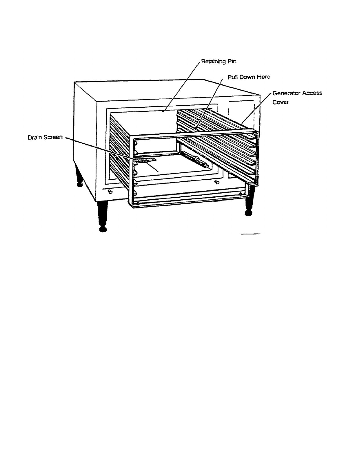
Figure 2-6. Pan Rack and Drain Screen Removal
INSTALLATION INSTRUCTIONS
After selecting and preparing the EconoCraft operating location, the steamer can be unpacked, positioned, and installed.
This section of Chapter 2 details inspecting and positioning the EconoCraft. Installation and connection of the power, water,
and drain lines are also detailed. After final setup and testing, the EconoCraft will provide years of reliable operation.
Assembly
Install the Drain Screen
1. Slide the pan rack out of the steamer. See Figure 2-6. Pull down on the
center of the top front bar of the rack so it clears the retaining pin as the
rack is slid out.
2. Install the drain screen over the drain hole at the rear of the compartment.
The pin on the drain screen must face downward. The small flanged edge
faces toward the front of the unit.
3. Slide the pan rack into the steamer compartment. Pull down on the top front
bar of the rack so that it clears the retaining pin.
Printed 5/93 Cleveland Range. Inc.

Model 24-CET-1 EconoCraft Service Manual. Chapter 2 Page 11
Install Four Legs
Do not install the EconoCraft without legs.
1. Place the EconoCraft on its left side.
2. Check that the feet are fully retracted into the legs. Do not overtighten, the feet
should easily screw in and out by using fingers only.
3. Install all four (4) legs in the bottom of the EconoCraft
4. Turn the steamer upright.
Position and Level EconoCraft
For efficient operation, the steamer should be level both front to back and side to
side. The legs of the EconoCraft are four inches long when the adjustable feet are
fully retracted. The adjustable feet can be extended approximately two inches,
providing adjustment for leveling the steamer.
1- Refer to the Installation Check List, Table 2-1. Check that all Preparation
Tasks arc complete. Check that all Unpacking and Assembly tasks are
complete.
2- Place the EconoCraft at the location where it will be used.
3- Adjust the retractable feet of the Econocraft to level the unit.
Install and Conne ct the Free Air Vented
Drain Lines
The drain outlet discharges exhaust steam and hot condensate from the steamer.
The drain outlet MUST be free air vented to equalize the pressure in the
EconoCraft with me atmosphere. Generating steam causes pressure to increase in
the unit: cold water flow into the condenser creates a vacuum (low pressure) in the
condenser. Without a free air vent, either high or low pressure in the compartment
will cause malfunction or damage. The openings at me top of the vent pipe and
drain outlet provide the EconoCraft with free air venting.
• Pressure build up in the steamer will cause steam and hot water leakage around
the door.
• A vacuum WILL implode the steamer and cause permanent physical damage.
Furnishing and installing the fittings and drain line is the responsibility of the
owner and/or installer. Figure 2-7 illustrates a drain layout recommended by
Cleveland Range. Observe the following instructions 10 determine the pipe size,
the number of fittings required, and the layout of the drain line path.
Page 12 EconoCraft Service Manual, Chapter 2 Model 24-CET-1
1.
The drain lines must be installed in compl
iance with the Basic Plumbing
WARNING
DEATH, INJURY, AND EQUIPMENT DAMAGE could
result from improper installation of the drain outlet lines.
THE DRAIN MUST BE FREE AIR VENTED.
Improper installation of these lines could void the
EconoCraft warranty. The following restrictions are
critical to the safety of personnel and equipment, and
must not be violated under any circumstances.
Do not connect the drain line into PVC pipe, or any other
drain material that cannot sustain 180° F.
Do not connect drains from any other equipment to the
EconoCraft drain line.
Do not connect the drain outlet extension line directly to
a floor drain or sewer line.
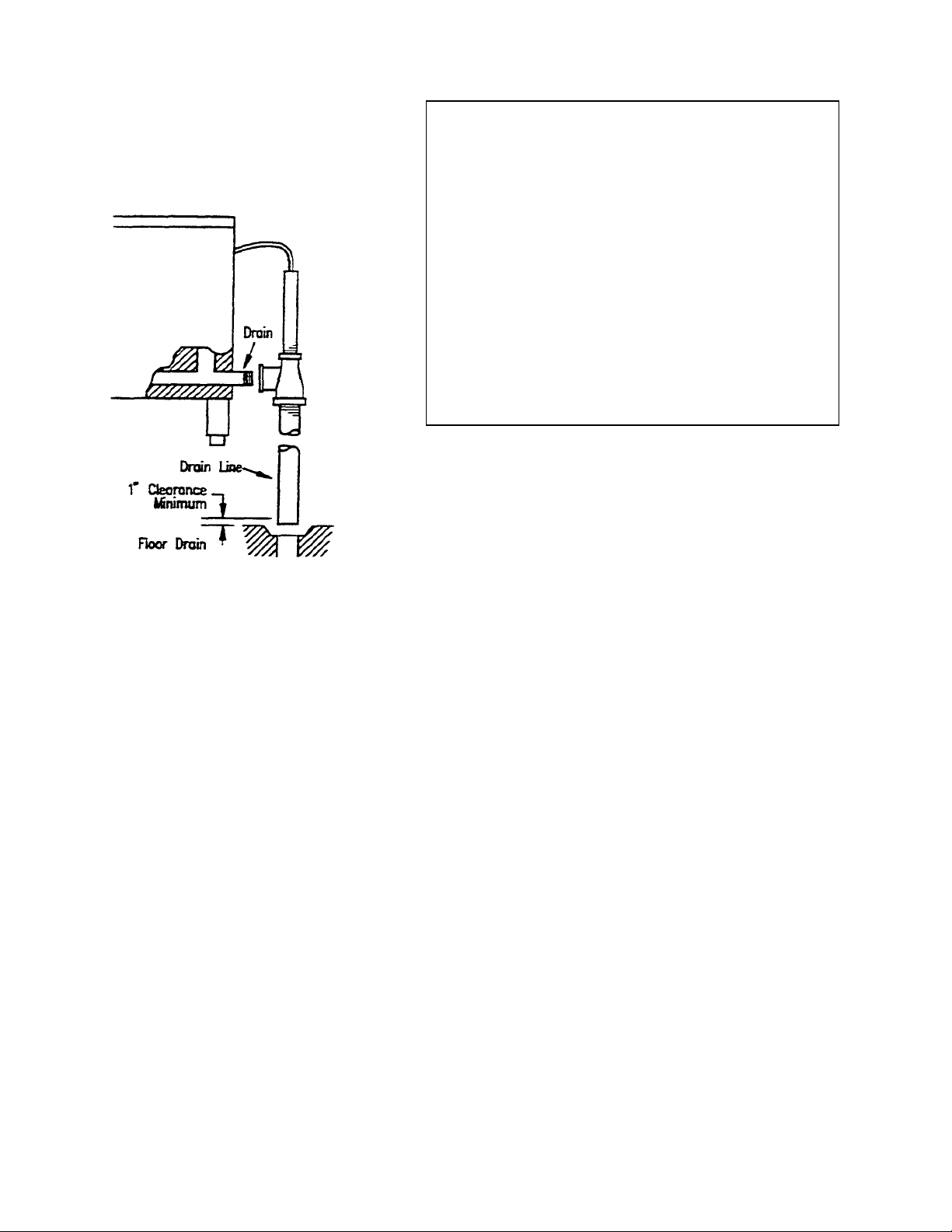
Figure 2-7. Drain Layout and Connections
Code of the Building Officials and Code Administrators International, Inc.
(BOCA), and the Food Service Sanitation Manual of the Food and Drug
Administration (FDA).
2. The pipe size used to extend the drain outlet to an open drain is
determined by me total length of pipe and number of bend finings
required to reach the open drain.
• If the drain outlet extension requires six feet or less of pipe, and no more than
two elbows are required, use 1-inch pipe and fittings.
• If the drain outlet extension requires six to twelve feet of pipe, or
requires three or more elbows, use 1-1/4-inch pipe and fittings.
3. The drain line must have a gravity flow from the EconoCraft drain outlet to
the floor drain. Do not install a p-trap in the drain line.
4. Free air venting requires a minimum of one inch clearance between the end of the
drain line and the top of the floor drain.
5. When assembling the pipe and fittings of the drain line, apply a hardening
type pipe sealant to the threads, and tighten them together FINGER
TIGHT ONLY. DO NOT USE A WRENCH.
6. Do not connect the steamer drain to drains or plumbing of any other equipment If
drains of two or more units are connected together, low pressure can develop,
causing an implosion and physical collapse of the steamer.
7. The EconoCraft is supplied with the drain assembly attached to the unit (Figure 2-
7). The overflow tube functions in free air venting and must extend upward from
the tee.
Printed 5/93 Cleveland Range, Inc.
Model 24-CET-1 EconoCraft Service Manual, Chapter 2 Page 13
Cleveland Range. Inc.
Printed
5/93
Install Electric Power Lines
Furnishing and installing the electrical power lines, switches, fuse boxes,
connectors and their accessories is the responsibility of the owner and/or installer.
Figure 2-8 illustrates an electrical layout recommended by Cleveland Range.
When installing the electrical power lines and accessories, observe the following
instructions.
1. In the United States, install the electrical power lines in accordance with local
codes and/or the National Electric Code, ANSI/NFPA No. 70-1990 (USA).
2. In Canada, install the electrical power lines in accordance with local codes
and/or the Canadian Electrical Code, CSA Standard C22.1 (Canada).
3. Install the proper size disconnect switch, circuit breaker or fuses, and wire and
conduit to conform to all local codes and the national codes cited above. See
Table 2-3 for wire requirements.
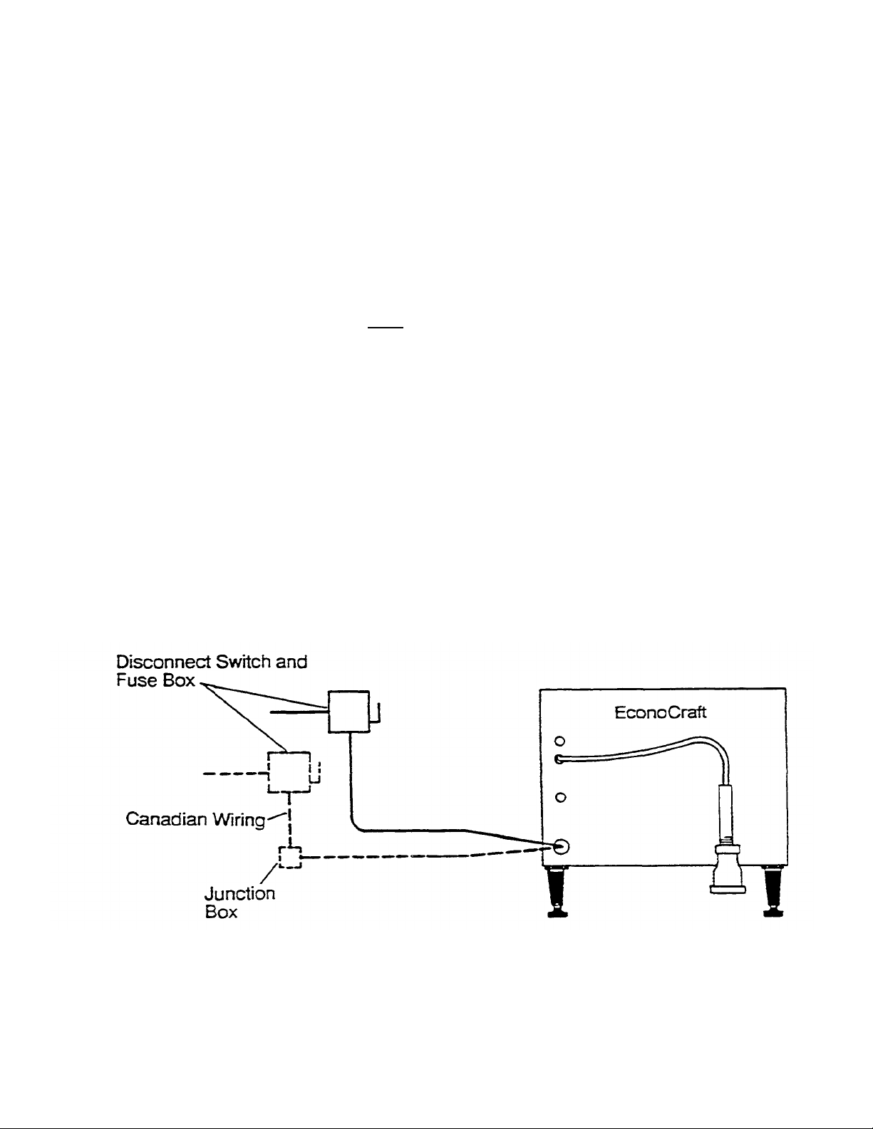
Figure 2-8. Electrical Layout
Page 14 EconoCraft Service Manual, Chapter 2 Model 24-CET-1
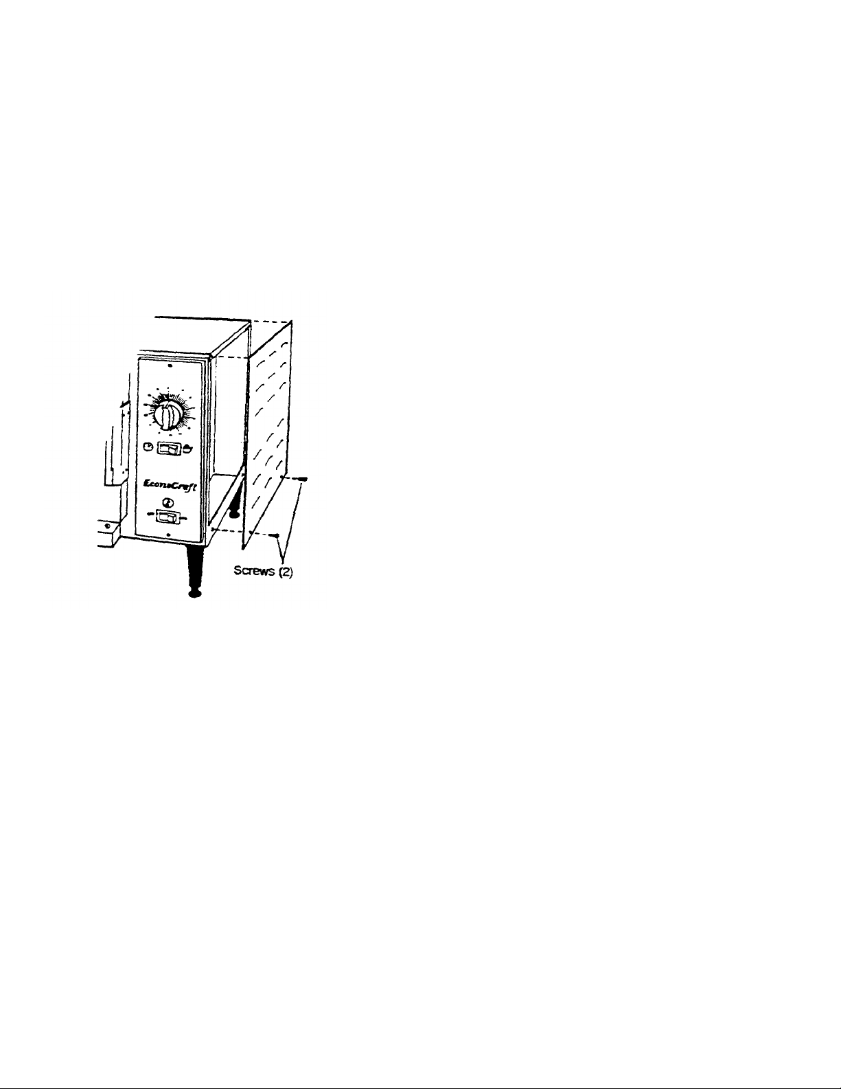
Figure
2-9.
Access Panel Removal
4. Install a separate disconnect switch and fuses sized to line amps (see
8 20 10
8 11 10
8 10 10
Table 2-3. Minimum Wire Requirements
LINE VOLTAGE KILOWATTS LINE
AMPS*
208 8 23 10
220 8 21 10
240
380/220 8 13 10
415/240 8 12 10
440
480
*All 3 Phase
**Use solidcopper wire rated for 75°C.
Table 2-3). The fuses may be an integral pan of the disconnect switch or
in a separate fuse box.
5. There should be a sufficient length of flexible conduit between the
EconoCraft connector and the wall so the unit can be moved for service.
• Canadian steamers are supplied wife six feet of flexible conduit for
compliance with Canadian Standards Association. The electrical supply
line must end in a junction box behind the steamer for connection of
the flexible cable from the steamer.
6. Each steamer MUST be electrically grounded by the installer.
7. The characteristics of the electric power supply must match the power
requirements specified on the EconoCraft product information plate. The
plate is located on the left side of the unit (refer to Figure 1-1 and 1-2).
8. EconoCrafts arc wired for 3 phase, but can be converted to single phase.
Contact an authorized service agency for more information.
WIRE
GAUGE**
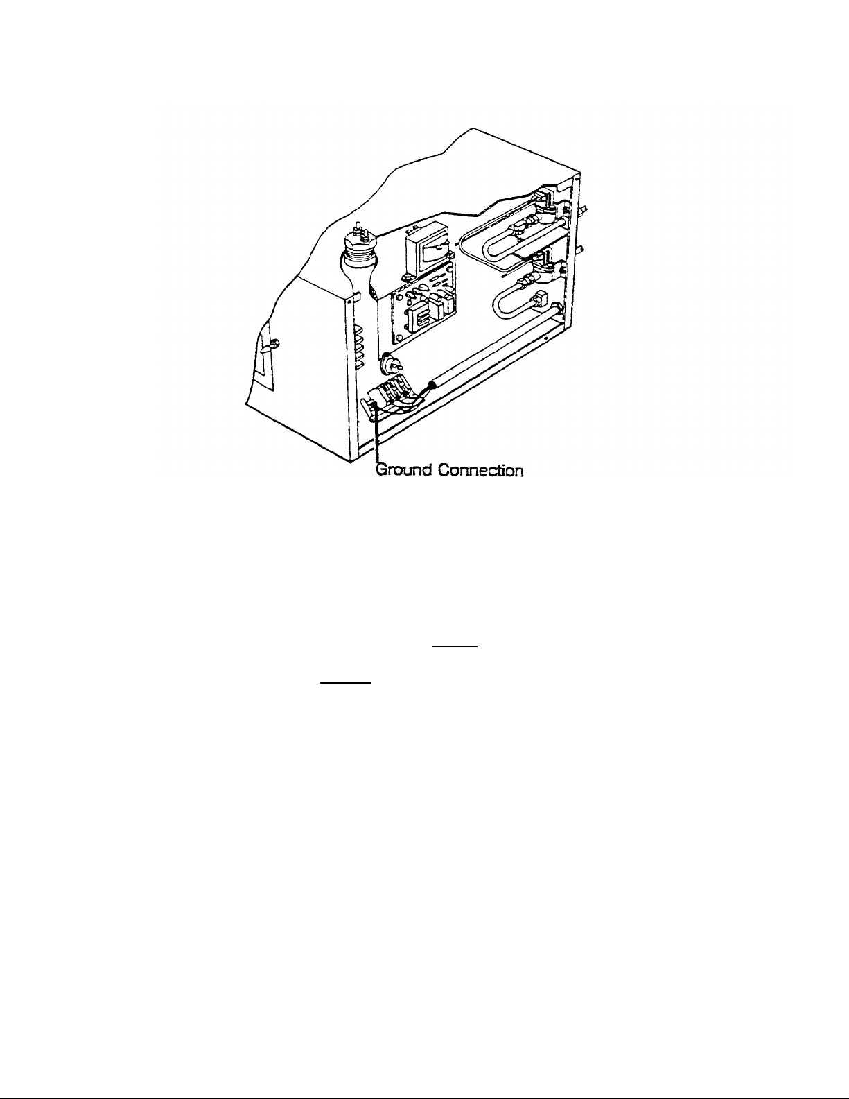
Verify that the electric power lines have been properly extended from me
external disconnect to the EconoCraft location. Connect the electrical lines
to the terminal block inside the right side access panel as described below.
1. Move the EconoCraft so the access panel can be easily reached.
2. Remove the access panel by removing the two screws (Figure 2-9) that
hold it in place. Save the screws.
3. Mechanically secure the flexible conduit to the electrical conduit access
hole (Figure 2-10). (See Canadian Wiring Considerations.)
4. The terminal block and ground connection are near the front of the side
opening. The unit has a terminal block for 3-wire DELTA connection.
5. Refer to the connection diagram. Figure 2-10, and connect the wires to the
terminal block and ground connector accordingly.
6. The steamer MUST be electrically grounded by the installer.
Primed 5/93 Cleveland Range, Inc.
Model 24-CET-1 EconoCraft Service Manual, Chapter 2 Page 15
I
nstall Water Supply Lines
Figure 2-10. Connection Diagram
7. EconoCrafts are wired for 3 phase, but are convertible to single phase. Contact
an authorized service agency for information on single phase connections.
8. If no further work is required inside the access panel, such as plumbing and leak
checks, secure the access panel with the two mounting screws (Figure 2-9).
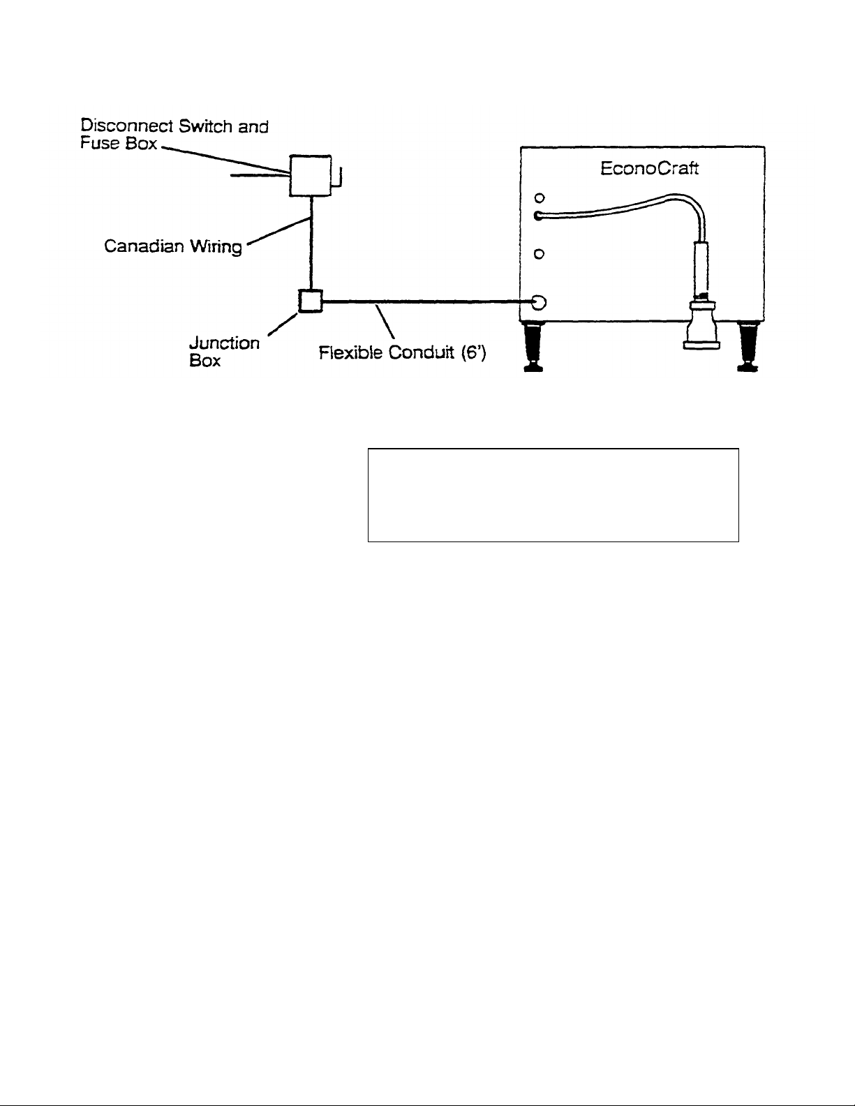
Canadian Wiring Considerations.
For all applications in Canada, install the electrical power lines in accordance with
local codes and/or the Canadian Electrical Code, CSA Standard C22.1 (Canada)
• Canadian steamers are supplied with six feet of flexible conduit connected to the
steamer and wired to the terminal block at the factory.
• The electrical supply line ends in a junction box behind the steamer for
connection of the EconoCraft flexible cable.
• Connect the wires from the EconoCraft flexible cable to those in the junction box
according to Figure 2-11.
• The steamer MUST be electrically grounded by the installer.
Furnishing and plumbing the water supply lines is the responsibility of the owner
and/or installer. Figures 2-13, 2-14, and 2-15 illustrate plumbing layouts
recommended by Cleveland Range. When installing water supply lines, observe
the following instructions.
Cleveland Range. Inc. Printed 5/93
Page 16 EconoCraft Service Manual, Chapter 2 Mode! 24-CET-1
Figure 2-11 - Canadian Connection Diagram
CAUTION
Do not connect warm or hot water supply to condensor
connection. If hot or warm water is supplied to this
connection, the steam condenser in the EconoCraft will
not work.
1. Connect a COLD water supply to the condenser connection (Figure 2-1).
2. Supply water pressure must have a minimum dynamic pressure of 35 psi (2.4
kg/cm2) and a maximum static pressure of 60 psi (4.1 kg/cm2).
3. The recommended size for the water supply lines is 1/4-inch IPS. This is
the size of generator and condenser connections on the rear of the
EconoCraft. If larger lines are used, a pressure reducer must be installed
in the supply line to maintain the pressure specified in ^2, above.
4. The National Sanitation Foundation (NSF) requires installation of a
check-valve in all supply lines in accordance with and as required by
local plumbing codes.
5. When a water treatment system is not installed, Cleveland Range recommends
the plumbing layout illustrated in Figure 2-13.
6. When installing a water treatment system, Cleveland Range recommends the
plumbing layout illustrated in Figure 2-15.
• The water supply to the condenser connection (Figure 2-1) can be
untreated-
• The treated water supply connects to the steam generator connection
(Figure 2-1).
7. When installing a hot water heater, Cleveland Range recommends the
plumbing layout illustrated in Figure 2-14.
Printed 5/93 Cleveland Range. Inc.
Model 24-CET-1 EconoCraft Service Manual, Chapter 2 Page 17
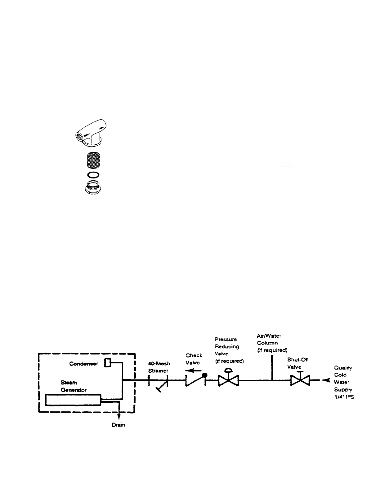
Figure
2-12.
Water Strainer
Connect Water Supply Lines
Connect the water supply lines paying particular attention 10 the following. Refer
10 the appropiate section below for information on the desired connection:
untreated, preheater, or SteamerGard.
1. Apply pipe dope or teflon tape to any threaded connection.
2. Rush the water supply lines before connecting the strainer.
3. When installing the water strainer(s), refer to Figure 2-12.
• Use a strainer with a 40 mesh screen.
• Make sure the arrow on the strainer body points in the direction of flow into
the steamer.
• Install the strainer so the access nut points down.
4. If water supply lines are larger than 1/4 -inch IPS, install a pressure reducer to
maintain the EconoCraft pressure requirements specified in Install Water
Supply Lines (page 15).
Single Untreated Water Connection
1. Refer to Figure 2-13-
2. Verify mat all components are installed in the single line before the tee that
divides the water flow between the steam generator and condenser.
Double Water Connection With Preheater
1. Refer to Figure 2-14.
2. Verify that each line connected to the steamer has a check valve and strainer
installed.
3. Verify that the hot water healer connects to the steam generator connection. The
condenser must have a cold water input to operate properly.
Figure 2-13. Single Water Connection
Cleveland Range, Inc. Printed 5/93
 Loading...