

Page 1
Cleveland Range
UNITED STATES
CANADA
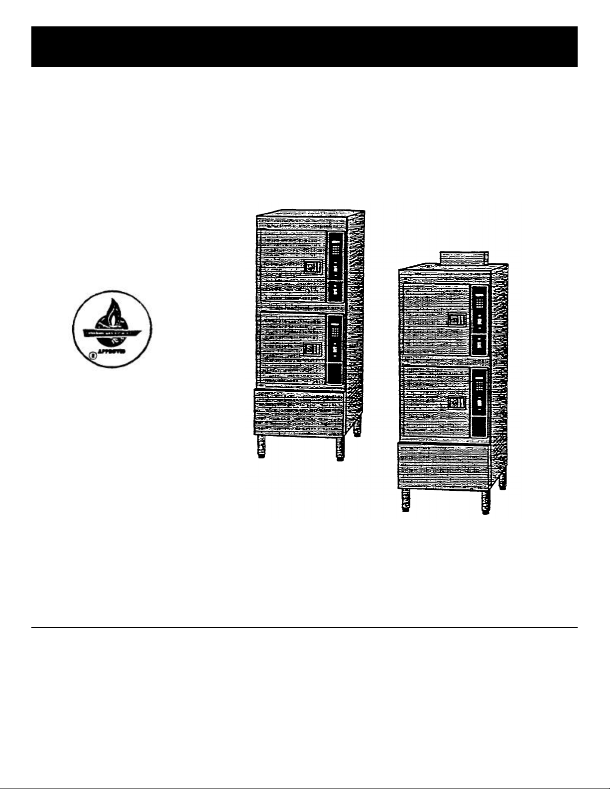
SteamCraft 10®
Convection Steamer
SERVICE
MANUAL
Printed 3/93
Cleveland Range, Inc.
1333 East 179th St.. Cleveland, Ohio 44110 Phone: (216) 451-4900 •
Telex: 98-0546 • FAX: (216) 481-3782
MODELS: 24-CEA-10, & 24-CGA -10
Garland Commercial Ranges
1177 Kamato Road
Mississaugha, Ontario. Canada L4W1X4
Phone: (416) 624-0260 - FAX: (416) 624-0623
Page 2

FOR YOUR SAFETY
Do not store or use gasoline or other flammable vapors or liquids in the vicinity of this
or any other appliance.
GAS LEAK INSTRUCTIONS
Post in a prominent location, instructions
to be followed in the event the user smells
gas. This information shall be obtained by
consulting the local gas supplier.
For safe and efficient operation of this equipment, this manual must be retained by the owner/user
for future reference.
PROTECTING WARRANTY COVERAGE
The warranty printed to the left specifies the owner/user's responsibility for proper installation, operation,
and maintenance of the SteamCraft 10. If these responsibilities are not met, toe Limited Warranty and/or
Extended Limited Warranty coverage may be adve rsely affected. The following table is provided to assist
the owner/user in meeting these responsibilities. In addition, the warranty advantages of installing a
SteamerGard water treatment system are explained after the table.
The Warranty Protection Table lists installation, operation, and maintenance factors that have in the past
adversely affected warranty coverage. The owner/user of a SteamCraft 10 should pay particular attention
to these factors to protect his warranty coverage. This table is not a comprehensive list of the owner/user's
responsibilities. Cleveland Range steam products are intended for use only by professionally trained
personnel To meet his responsibilities, the owner/user must supplement this guide with any additional
actions consistent with the operation of steam generating food preparation equipment by a trained
professional.
Warranty Protection Table
SUBJECT PAGE
REFERENCE
Electrical Power Requirements & Line Voltage 10
Water Quality Requirements & Analysis 11
Water Pressure 16
Vented Drain 20
Level Operation 19
Blowdown Frequency 55 & 63
Steam Generator Maintenance & Maintenance Records 67
Descaling Frequency & Procedure 68
Approved Chemical Cleaners 68
Authorized Maintenance & Repair 74
SteamerGard Water Treatment System
A SteamerGard water treatment system protects the SteamCraft 10 from impurities contained in regular
lap water, especially Total Dissolved Solids (TDS) which cause lime and scale deposits in steamer
equipment. The protection is so effective that Cleveland Range increases toe warranty coverage on a
Steam Craft 10 installed in conjunction with a SteamerGard system to five years for parts and three years
for labor on water related components, elements, valves, generators, piping, etc. However, even with a
SteamerGard system installed, the owner/user should follow toe guidance of the Warranty Protection
Table.
Page 3

Models 24-CGA-10 and 24-CEA-10 SteamCraft 10 Service Manual
Table of Contents
Chapter Page
CHAPTER 1. PRODUCT IDENTIFICATION 1
MODEL NUMBER 1
SERIAL NUMBER 1
PRODUCT INFORMATION PLATE 1
CHAPTER 2. INSTALLATION INSTRUCTIONS 7
INTRODUCTION 7
INSTALLATION POLICIES 7
INSTALLATION OVERVIEW 8
PREPARATION FOR INSTALLATION 10
Protecting The SteamCraft 10 10
Electric Power Requirements 10
Gas Supply Requirements 10
Exhaust Hood Requirements – All Models 10
Water Quality Requirement s 11
Softened, Treated, or Filtered Water 16
Water Supply System 16
Selecting The Operating Location 17
INSTALLATION INSTRUCTIONS 18
Unpacking & Inspection 18
Shipping Damage Instructions 19
Position & Level The SteamCraft 10 19
Adjustable Leveling Legs 19
Positioning & Leveling 19
Install Slide Racks 20
Install & Connect The Free Air Vented Drain Lines 20
Exhaust Hood Ventilation – All Models 22
Install Electric Power Lines 22
Connect Electrical Line 23
Install Water Supply Lines 24
Connect Water Supply Lines 26
General Connection Requirements 26
Untreated Water Connection (Without SteamGard) 27
Treated Water Connection (With SteamGard) 27
Testing Water Supply Lines 27
Install & Connect Gas Supply Lines 27
Leak-Testing Gas Supply Lines 28
Pressure Testing The Gas Supply Lines 29
Bleed Air From The Gas Supply Lines 30
Burner Ignition Test (Gas -Fired Models Only) 31
Final Setup & Checkout 33
Cleveland Range, Inc . Printed 3/93
Page 4

Page ii SteamCraft 10 Service Manual Models 24-CGA-10 0 and 24-CEA-10
Table of Contents (continued)
Chapter Page
Installation Checks 33
Operating Tests 34
Operating Test Preparation 34
Blowdown Inspection Procedure 35
Operating Test Procedures 35
Timer Test Procedures – Key Pad Control Panel 37
Timer Test Procedures – Dial Timer Control Panel 38
CHAPTER 3. OPERATION 41
INTRODUCTION 41
DIFFERENCES AMONG MODELS 41
Atmospheric Generator Models 41
Pressure Generator Models 41
OPERATIONAL SAFETY 41
BURNER LIGHTING 43
GAS LEAK INSTRUCTIONS 43
OPERATING MODES 43
Manual Operation 43
Timed Operation 43
Manual Timer 43
Steam Generator BlowDown 44
MAIN DISCONNECT SWITCH 44
CONTROL PANELS 44
COOKING OPERATIONS KEY PAD CONTROL PANEL 46
Summary Of Cooking Operations 46
Power ON (Automatic Fill) 47
Start Steam Supply 47
Inspect The Cooking Compartment 47
Preheat The Cooking Compartments 48
Place Food Into The Cooking Compartment(s) 49
Select The Operating Mode 49
Timed Cooking Procedure 50
Manual Cooking Procedure 51
Power OFF (Automatic Blowdown) 52
Blowdown Frequency 52
Blowdown Procedure 53
Shut Down And Cleaning (At End Of Day Or Shift) 53
DIAL TIMER CONTROL PANEL SUMMARY 55
COOKING OPERATIONS – DIAL TIMER CONTROL PANEL 56
Summary Of Cooking Operations 56
Power ON (Automatic Fill) 56
Printed 3/93 Cleveland Range, Inc.
Page 5

Models 24-CGA-10 and 24-CEA-10 SteamCraft 10 Service Manual Page iii
Table of Contents (continued)
Chapter Page
Start the Steam Supply 57
Inspect the Cooking Compartment 57
Preheat the Cooking Compartment(s) 57
Place Food into The Cooking Compartment(s) 58
Select the Operating Mode 58
Timed Cooking Procedure 58
Manual Cooking Procedure 59
Remove Food from The Cooking Compartment(s) 59
Power OFF (Automatic Blowdown) 60
Blowdown Frequency 60
Blowdown Procedure 60
Shut Down And Cleaning (At End Of Day Or Shift) 61
CHAPTER 4. PREVENTATIVE MAINTENANCE AND TROUBLESHOOTING 63
INTRODUCTION 63
MAINTENANCE RECORDS 63
DAILY MAINTENANCE 63
Blowdown Steam Generator 63
Clean SteamCraft 10 63
WEEKLY MAINTENANCE 63
Clean Drain 63
MONTHLY MAINTENANCE 64
Descale Steam Generator 64
YEARLY MAINTENANCE 67
Clean Water Line Strainer 67
TROUBLESHOOTING NOTES 70
CHAPTER 5. COMPONENT AND CIRCUIT FUNCTIONS 71
INTRODUCTION 71
Models Covered In This Chapter 71
Figures and Illustrations 71
SteamCraft 10 Variations 71
Steam Generator Power Source 71
Control Panel Type 72
THEORY OF OPERATION 72
Steam Generator Water Filling Cycle 72
Steam Generator Preheating 74
Steaming Functions For Model 24-CEA-10 75
Steaming Functions For Model 24-CGA-10 76
Gas Burner Ignition and Combustion Functions – Model 24-CGA-10 79
Burner Ignition and Control System 79
Cleveland Range, Inc. Printed 3/93
Page 6

Page iv SteamCraft 10 Service Manual Models 24-CGA-10 and 24-CEA-10
Table of Contents (continued)
Chapter Page
Condenser and Drain Functions 80
Condenser Operation 80
Drain Valve Functions 81
Shutdown, Steam Generator And Float Cylinder Rise Functions 82
STEAMCRAFT 10 ELECTRICAL CIRCUITS – Model 24-CEA-10 83
High Voltage Circuit 83
120 VAC Circuit 83
STEAMCRAFT 10 ELECTRICAL CIRCUITS – Model 24-CGA-10 83
STEAMCRAFT 10 TIMER CIRCUITS 84
ELECTRICAL CIRCUIT COMPONENTS 84
Terminal Bloc k 84
ON/OFF Switch 85
TIMED/MANUAL Switch 85
3-Minute Timer 85
Float Assembly 86
Rinse Solenoid Valve 87
Drain Solenoid Valves 87
Water Fill Solenoid Valves 87
Condenser Solenoid Valves 87
Preheat Thermostat 88
Key Pad and Dial Timers 88
Electronic Key Pad Timer 88
Compartment Thermostat (Electronic Key Pad Units Only) 89
Mechanical Timer 89
3-Second Timer And Buzzer (Mechanical Timer Units Only) 89
Heater Element – Model 24-CEA-10 89
Dryer Element – Model 24-CEA-10 89
High Temperature Limit Switch 89
Combustion Control Module – Model 24-CGA-10 90
Combustion Air Blower 90
Air Prover Pressure Switch 90
Pilot Spark Igniter 90
Automatic Gas Valve 90
Steam Relief Solenoid Valve – Model 24-CGA-10 90
Compartment Steam Solenoid Valves – Model-CGA-10 90
CHAPTER 6. COMPONENT TESTING GUIDE 91
INTRODUCTION 91
Models Covered In This Chapter 91
Figures And Illustrations 91
Nominal Voltage Reference 91
Printed 3/93 Cleveland Range, Inc.
Page 7

Models 24-CGA-10 and 24-CEA-10 SteamCraft 10 Service Manual Page v
Table of Contents (continued)
Chapter Page
COMPONENT TESTING FUNDAMENTALS 92
Visual Check 92
Connections and Wiring 92
Solenoid Valves 93
General Considerations 93
Normally Open And Normally Closed Valves And Contacts 93
Water Pressure and Control Valves 93
Measuring Resistance Through The Solenoid 93
Jammed or Blocked Valves 93
Thermostatic Snap Switches 95
Heater Element 95
Resistance Measurements 95
Insulation Resistance Measurements 96
Voltage Measurements 96
INITIAL TEST PROCEDURE – INTRODUCTION 96
Test Procedures Layout and Conventions 96
INITIAL TEST PROCEDURE – GENERAL PREPARATIONS 97
Model Numbers and Test Procedure Variations 97
INITIAL TEST PROCEDURE – MODEL 24-CGA-10 98
Set Up the Initial Test Conditions 98
COMPONENT TEST PROCEDURES 123
Initial Conditions for All Testing 123
CT:1 Drain (3-Way) Solenoid Valves 123
CT:2 3-Minute Timer 124
CT:3 Rinse Solenoid Valves 125
CT:4 Water Fill Solenoid Valves 126
CT:5 ON/OFF Switch 127
CT:6 Float Assembly 128
CT:7 Gas Control Transformer – 24 Volt Model 24-CGA-10 131
CT:8 Preheat Thermostat (Steam Generator) 131
CT:9 TIMED/MANUAL Switch 132
CT:10 Condenser Solenoid Valves 133
CT:11 Steam Relief Solenoid Valve – Model 24-CGA-10 135
CT:12 Compartment Steam Solenoid Valve – Model 24-CGA-10 136
CT:13 Mechanical Timer 137
CT:14 & CT:15 3-Second Timer And Buzzer (Mechanical Timer Units Only) 137
CT:16 Electronic Timer Transformer – 24 Volt 138
CT:17 Electronic Key Pad Timer 139
CT:18 Compartment Thermostat (Key Pad Timer Units Only) 141
CT:19 Transformer – Model 24-CEA-10 142
CT:20 & CT:21 Heater Contactor – Model 24-CEA-10 142
Cleveland Range, Inc. Printed 3/93
Page 8

Models 24
-
CGA
-10
and
24-CEA
-
10
Table of Contents (continued)
Chapter Page
CT:22 High Temperature Limit Switch – Model 24-CEA-10 144
Terminal Block 145
CT:23 & CT:24 Heater & Dryer Elements – Model 24-CEA-10 145
CT:25 Relay R-1 – Model 24-CEA-10 147
Burner Ignition & Control System Components – Model 24-CGA-10 147
CHAPTER 7. ILLUSTRATED PARTS LISTS 149
INTRODUCTION 149
Parts Differences Among SteamCraft 10 Steamers 149
Electrical Schematics And Wiring Diagrams 149
Ordering Parts 149
CHAPTER 8. IGNITION MODULE 199
INTRODUCTION 199
HONEYWELL & WHITE -RODGERS MANUALS 199
Printed 3/93 Cleveland Range, Inc.
Steam Craft 10 Service Manual
Page 9

Models 24-CGA-10, 24-CGP -10, 24-CEA-10, 24-CEP-10 SteamCraft 10 Service Manual, Chapter 1 Page 1
CHAPTER 1. PRODUCT IDENTIFICATION
Cleveland Range, Inc. assigns two product identification numbers to each
SteamCraft 10: a model number and a serial number. The model number
identifies the product characteristics. The serial number identifies the individual unit.
MODEL NUMBER
The operating section of this manual (Chapters 1 through 4) covers four
models of the Steam Craft 10 steamers:
• Gas fired atmospheric generator 24-CGA-10
• Gas fired pressure generator. 24-CGP-10
• Electric atmospheric generator. 24-CEA-10
• Electric pressure generator 24-CEP-10
The service section of this manual (Chapters 5 through 8) covers only the
atmospheric models:
• Gas fired atmospheric generator 24-CGA-10
• Electric atmospheric generator. 24-CEA-10
Each character of the model number identifies a characteristic of the
steamer. The Steam Craft 10 is 24 inches wide; a Convection steamer,
Electric or Gas powered, Atmospheric or Pres surized steam generator, and
has the capacity for 10 cooking pans.
SERIAL NUMBER
PRODUCT INFORMATION PLATE
This manual covers all standard features and options available on
SteamCraft 10 steamers. Other than selection of options, there are
presently no significant design, parts, or operating differences among
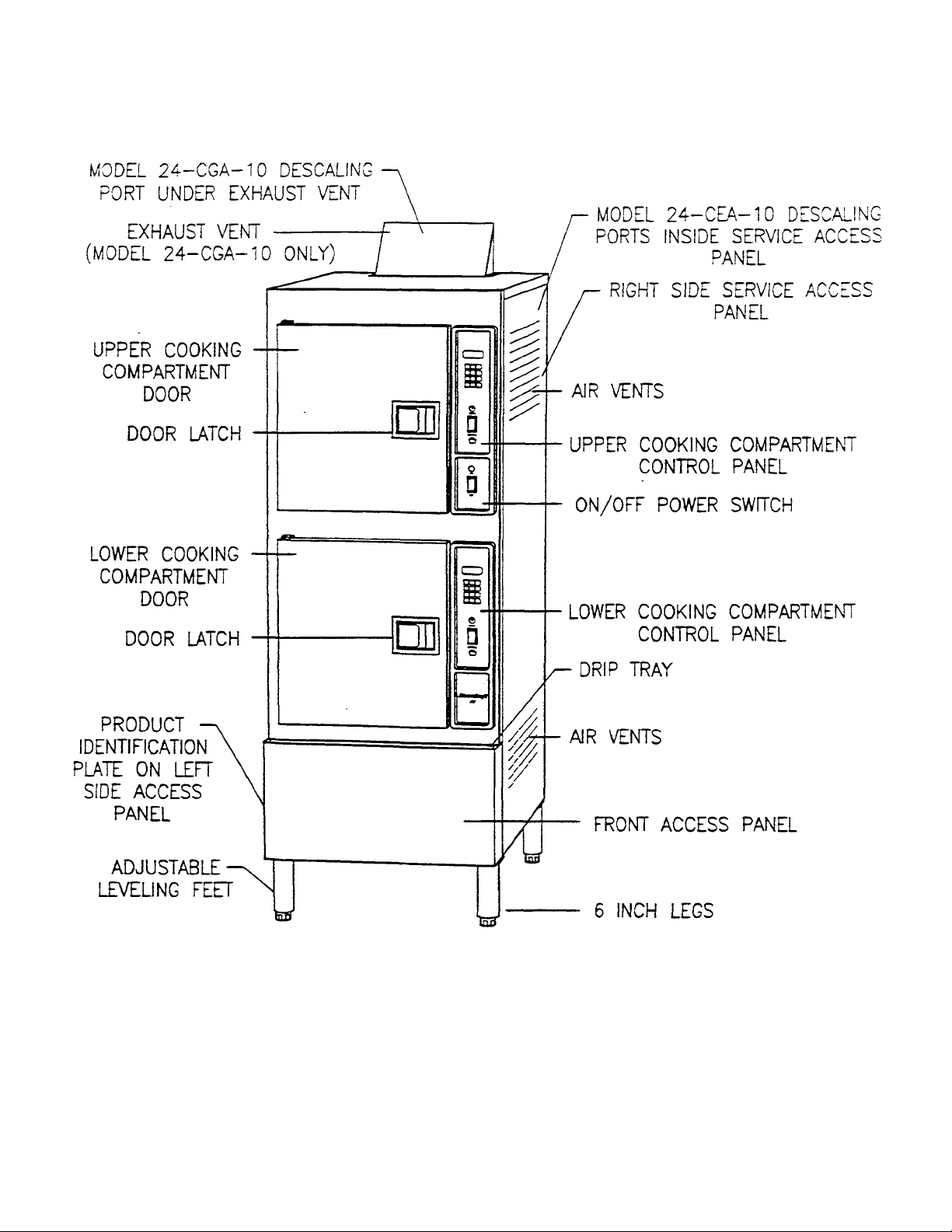
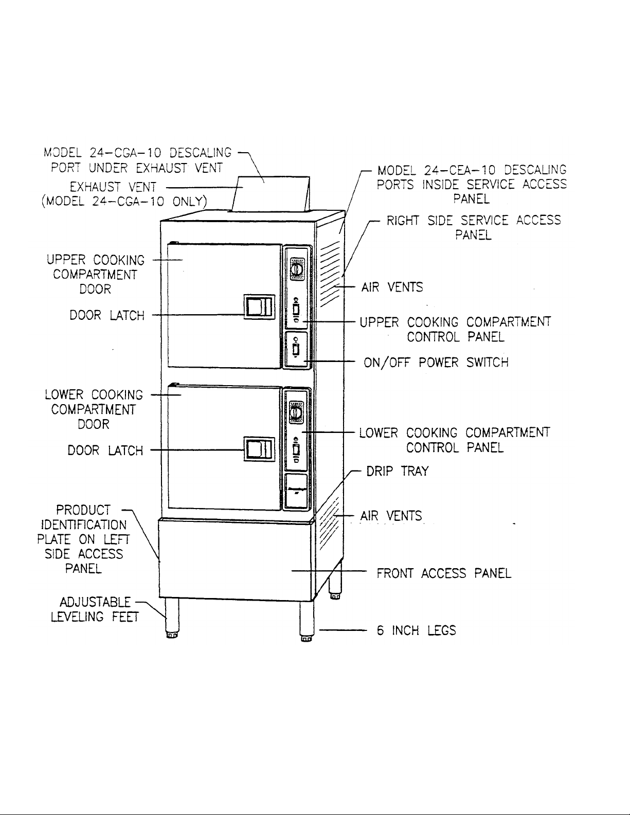
steamers with the same model number. Figure 1-2, Sheets 1 through 4
illustrate the four SteamCraft 10 models and identify the major components.
During manufacture, SteamCraft 10's are assigned individual serial num-
bers. A typical SteamCraft 10 serial number is: WC-7350-90G-02. The left
half of the number carries design information. The right half of the number
contains the manufacturing date and the unit of the manufacturing lot The
date of our sample number is 90G-02:90=1990, G=July. 02=the second unit
of the manufacturing lot Serial numbers arc used when explaining differ-
ences in design, parts, or operation among units with the same model
number. For example: a particular part may be used on SteamCraft 10's
with serial numbers before WC-7350-90G-02, and a different part used on
steamer WC-7350-90G-02 and those manufactured after it.
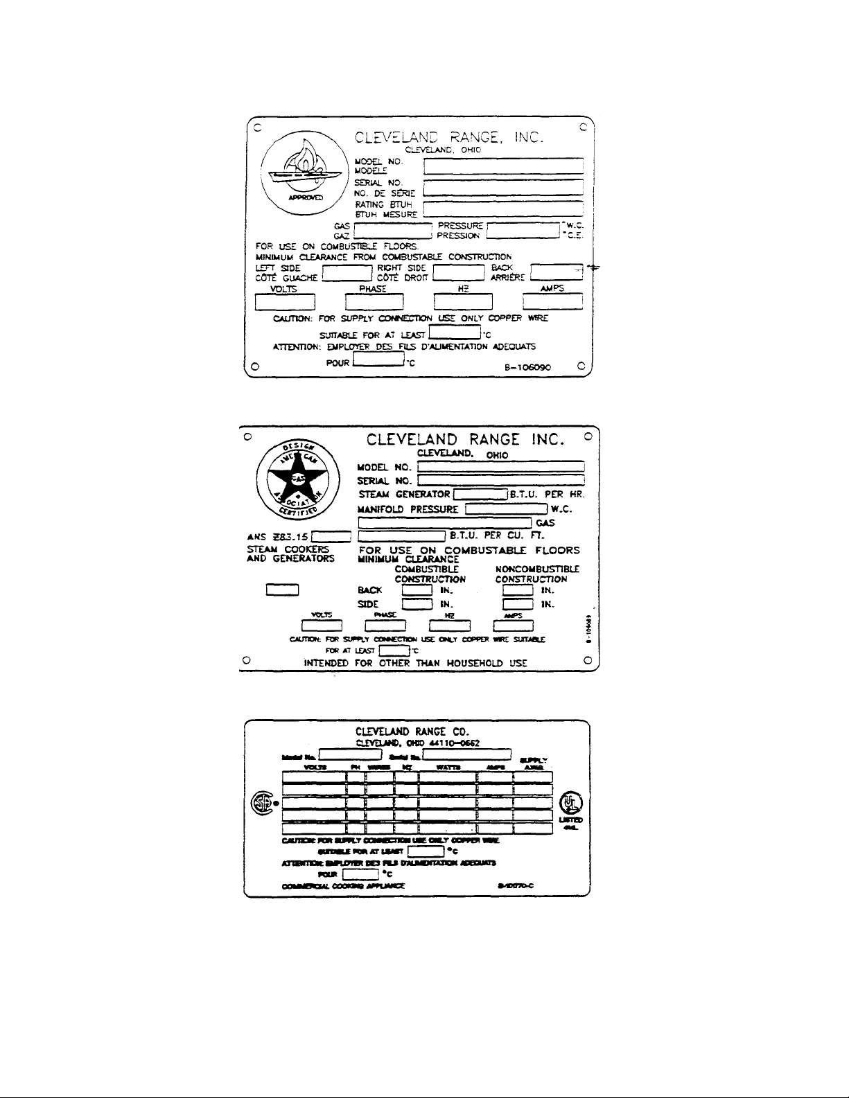
The Product Information Plates list the unit's model and serial numbers, and
power and wiring requirements. These plat es are located on the left side
panel, in the lower right corner. Figure 1-1 illustrates typical SteamCraft 10
Product Information Plates. Refer to me Figure 1-2 for the location of the
plates.
Page 10
Page 2 Chapter 1, SteamCraft 10 Service Manual Models 24-CGA-10, 24-CGP-10, 24-CEA-10, 24-CEP-10
Figure 1-1. SteamCraft 10 Product information Plates
Printed 3/93 Cleveland Range, Inc.
Page 11
Models 24-CGA-10, 24-CGP-10, 24-CEA-10, 24-CEP-10 SteamCraft 10 Service Manual, Chapter 1 Page 3
Figure 1-2. SteamCraft 10, Models 24-CGA-10 and 24-CEA-10
with Key Pad Control Panel (Sheet 1 of 4)
Cleveland Range, Inc. Printed 3/93
Page 12
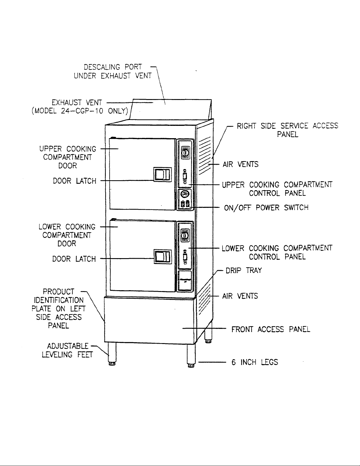
1, SteamCraft 10 Service Manual Models 24-CGA-10, 24-CGP-10, 24-CEA-10, 24-CEP-10 Page 4
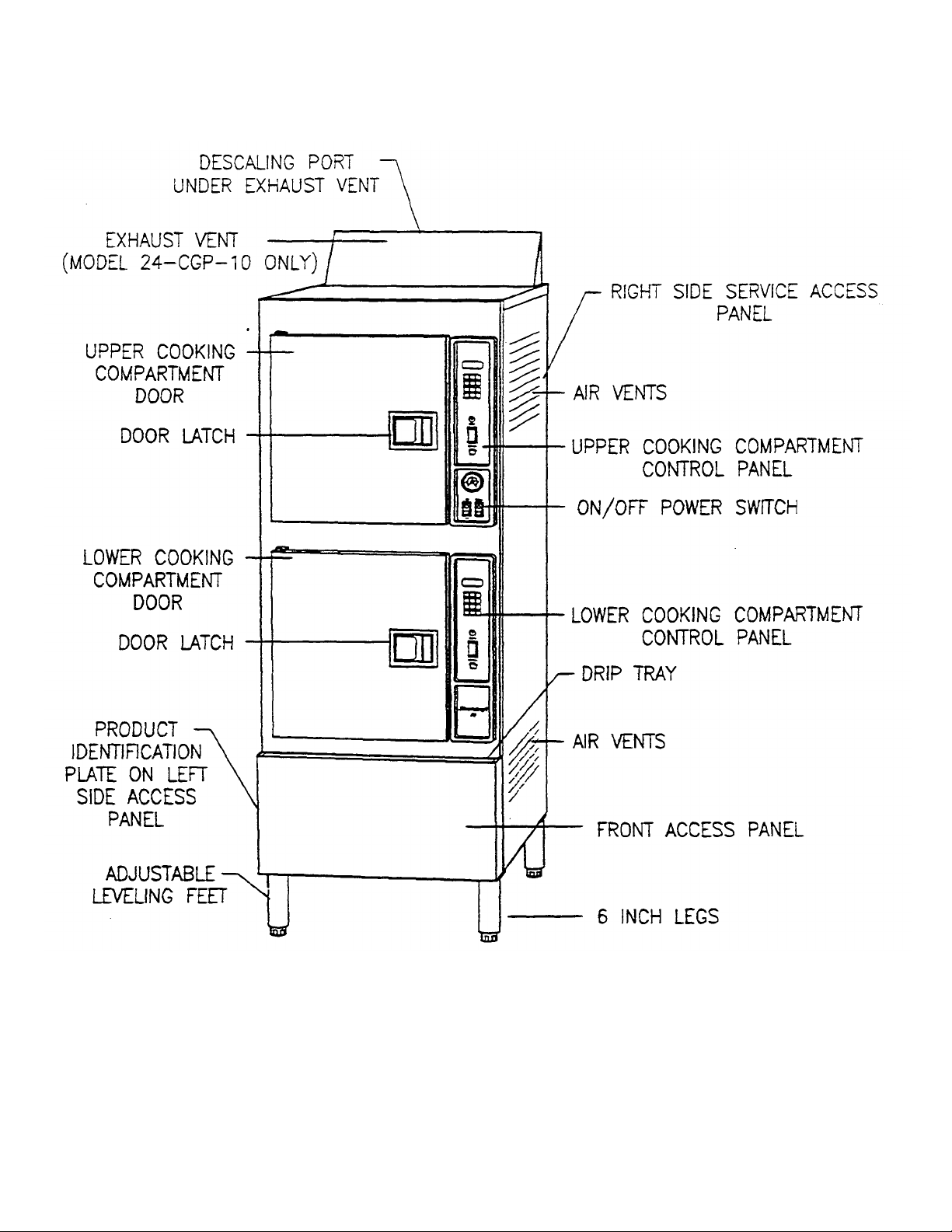
Figure 1-2. SteamCraft 10, Models 24-CGP-10 and 24-CEP-10
with Key Pad Control Panel (Sheet 2 of 4)
Printed 3/93 Cleveland Range, Inc.
Page 13
Models 24-CGA-10, 24-CGP-10, 24-CEA-10, 24-CEP-10 SteamCraft 10 Service Manual, Chapter 1 Page 5
Figure 1-2- SteamCraft 10, Models 24-CGA-10 and 24-CEA-10
with Dial Timer Control Panel (Sheet 3 of 4)
Page 14
Page 6 Chapter 1, SteamCraft 10 Service Manual Models 24-CGA-10, 24-CGP-10, 24-CEA-10, 24-CEP-10
Figure 1-2. SteamCraft 10, Models 24-CGP-10 and 24-CEP-10
with Dial Timer Control Panel (Sheet 4 of 4)
Page 15

Models 24-CGA-10, 24-CGP-10, 24-CEA-10, 24-CEP-10 SteamCraft 10 Service Manual, Chapter 2 Page 7
CHAPTER 2. INSTALLATION INSTRUCTIONS
This manual and several components are packaged inside the Steam Craft 10
shipping carton. Only enough of the carton shoul d be opened to remove this
manual. Do not remove the Steam Craft 10 from the carton until just before
installation. If the shipping carton has already been removed and discarded, protect
the Steam Craft 10 from dirt and damage during storage, site preparation, and
installation as described in Protecting The Steam Craft 10, page 10.
WARNING
DEATH, INJURY, AND EQUIPMENT DAMAGE
could result from improper installation of the
SteamCraft 10, or from installation of a unit damaged during shipment or storage. Either of these
conditions could also void the equipment warranty.
DO NOT INSTALL a SteamCraft 10 suspected of
damage.
Install the SteamCraft 10 according to the policies
and procedures outlined in this manual.
INTRODUCTION
This chapter is a guide for installation of the SteamCraft 10, model numbers 24CGA-10,24-CGP-10,24-CEA-10 and 24-CEP-10. This guide is for use by qualified
professionals, and does not include all procedures and precautions in the common
domain of licensed plumbers, pipe fitters, and electricians, or experienced food
service equipment installers. This guide must be used in conjunction with
professional experience and a thorough under standing of the local, state, and
national utility, construction and sanitation codes; the most prominent of which are
listed in the Installation Policies section below.
Before starting installation, the owner and the installer should read through this
chapter and thoroughly understand and agree upon:
• The installation policies of Cleveland Range, Inc. as stated in Installation
Policies.
• An installation plan based on the Installation Overview and Installation Check
List
• Responsibility for feed water quality and its testing as described in Preparation
For Installation, Water Quality Requirements.
INSTALLATION POLICIES
The SteamCraft 10 must be installed by qualified plumbing and electrical
personnel, working to all applicable national and local codes.
• In the U.S.A., equipment installation must comply with the Basic Plumbing
Code of the Building Officials and Code Administrators International, Inc.
(BOCA), the National Fuel Gas Code, ANSI Z223.1-(latest edition), the
National Electric Code, ANSI/NFPA No. 70-(latest edition), and the Food
Service Sanitation Manual of the Food and Drug Administration (FDA).
• In Canada, equipment installation must comply with the CAN/CGA-B 149
Installation Code, the Canadian Electrical Code CSA C221and any other
applicable national and local codes.
Cleveland Range, Inc. Printed 3/93
Page 16

Previous Page
Page 8 Chapter 2, SteamCraft 10 Service Manual Models 24-CGA-10, 24-CGP-10, 24-CEA-10, 24-CEP-10
Chec
k electric power requirements.
1
,2
10
Check gas supply requirements (gas models only).
2,3,4 10
Test supply water quality.
5,6 11
Select water treatment system.
6 16
Select operating location
-
17
Installation
Position and level steamer.
11 19
Install exhaust hood.
12 22
24
6 26
Test water supply lines.
27
Install and connect gas supply lines (gas models only).
2,3,4 27
INSTALLATION OVERVIEW
• Cleveland Range designs and manufactures equipment ID comply with
applicable standards for manufacturers. Included among these certification
agencies are: UL, A.G.A., ASME/N.Bd., NSF, CSA, CGA, ETL, and
others.
• This equipment is designed and certified for safe operation only when
permanently installed in accordance with local and/or national codes. Many
local codes exist, and it is the responsibility of the owner and installer to
comply with these codes.
• In no event shall the manufacturer assume any liability for damage or injury
resulting from installations which are not in strict compliance wit h the
Installation Instructions and the codes cited above. Specifically, the
manufacturer will not assume any liability for damage or injury resulting
from improper installation of equipment, including, but not limited to,
temporary or mobile installations .
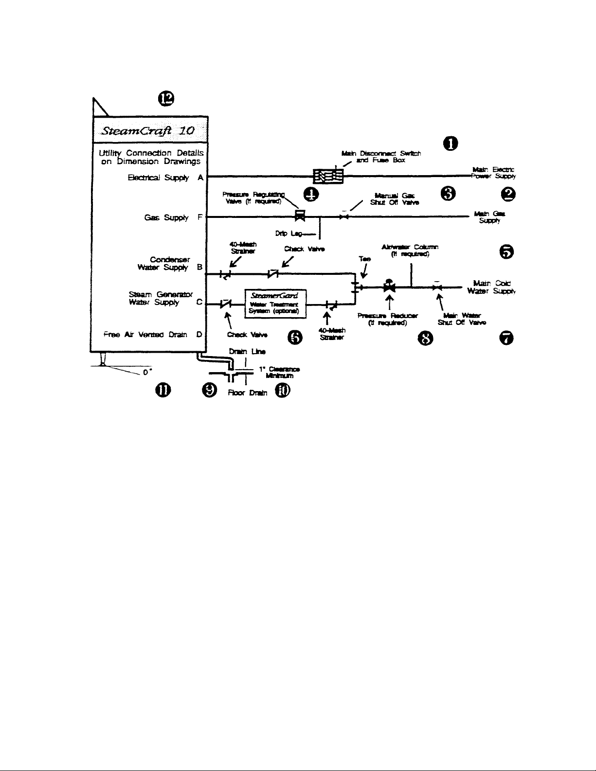
SteamCraft 10 installation is presented in two parts: preparation and installation. Table 2-1 and Figure 2-1 provide an overview of installation process.
Figure 2-1, Schematic Installation Diagram, illustrates the utility lines and
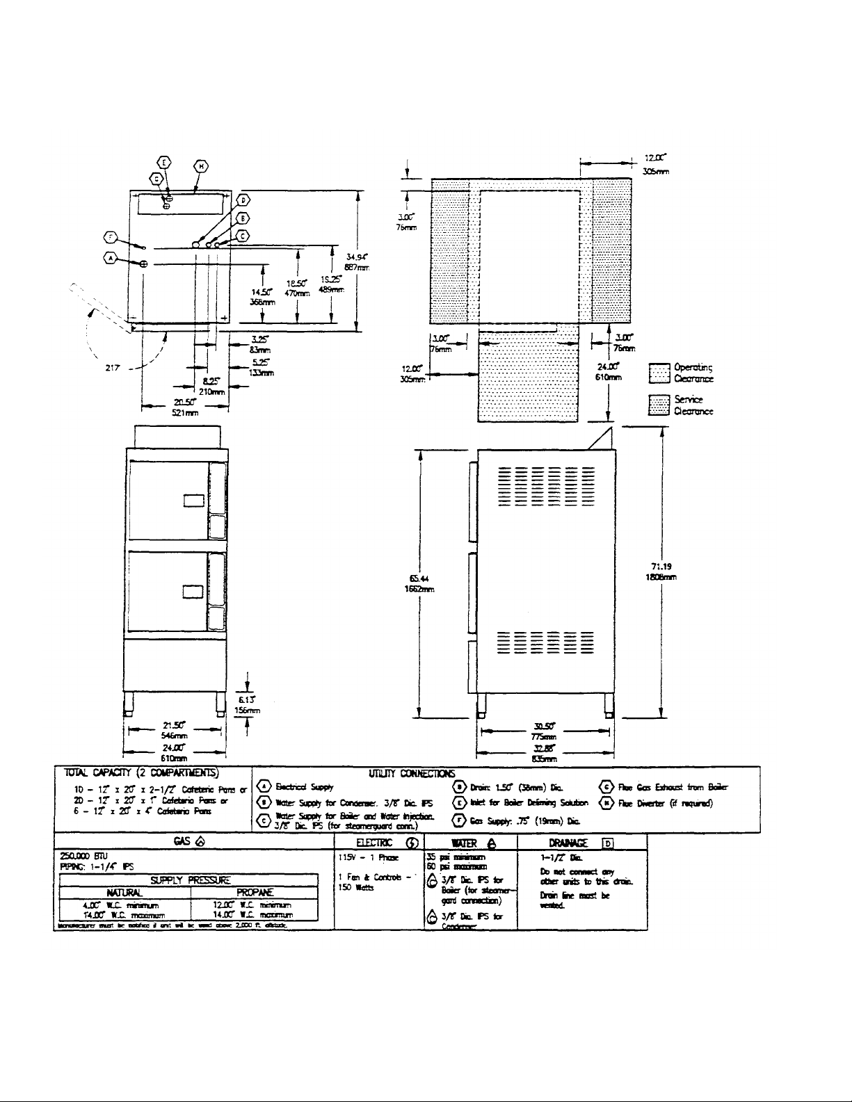
connections required to install the SteamCraft 10. The Dimension Drawings,
Figure 2-2, show the required utility connection points, dimensions, and
clearances for each of the SteamCraft 10 models.
Table 2-1, Installation Check: List, outlines the overall installation process by
listing, in recommended sequence, the major tasks to be performed. For each
task the table references applicable notes from Figure 2-1 and the manual
pages on which the task instructions begin. Complete the preparation tasks in
sequence, and then the installation tasks. Installation requirements may vary
from site to site; adapt the check list accordingly.
Table 2-1. Installation Check List
(Refer to Figure 2-1)
TASK FIGURE 2-1
NOTES
Preparation
Check exhaust hood requirements. 12 10
Unpack, inspect, and protect me unit.
Install and connect drain line. 9,10 20
Install and connect electrical line. 1,2 22
Install and connect water supply lines.
Install water treatment system.
5,6,7,8
PAGE REFERENCE COMPLETED
18
Test gas supply lines (gas models only).
Bleed gas line at union upstream of gas valve (gas models only) 3 30
Test burner igniter control module (gas models only).
Perform final setup and checkout
28
31
33
Page 17
Models 24-CGA-10, 24-CGP -10. 24-CEA-10, 24-CEP-10 SteamCraft 10 Service Manual Chapter 2 Page 9
INSTALLATION DIAGRAM NOTES
1 . For each unit, the installer must provide a ground con-
nection and a separate fused disconnect switch.
2. The Product Identification Plate, located in the lower right
corner of the left side panel, specifies the electric power
and gas utility requirements.
3. A manual shut off valve and a drip leg must be installed
between the main gas supply and the steamer supply
lines- Bleed air from the gas line at the fitting closest to
the internal automatic gas valve. Refer to Figure 2-14 for
the recommended component arrangements.
4. Never exceed 14" water column (1/2 psi) gas pressure. If
the gas supply pressure exceeds 14" water column, a
pressure regulating valve must be installed in the gas
supply plumbing to reduce the gas pressure to less than
14" water column.
5. The unit must have a cold water supply, NOT HOT. The
water supply must meet the quality requirements of
Table 2-2, and the pressure requirements on page 16.
6. A SteamerGard filtering system is recommended when
water quality does not meet the Table 2-2 requirements,
Figure 2-1. Schematic Installation Diagram
7. Run a single water line between the main cold water supply
and the tee. The two separate steam generator and
condenser/blowdown supply lines are relatively short.
8. A manual shut off valve must be installed between the main
water supply and the steamer supply lines- Refer to Figure
2-10 or 2-11 for recommended component arrangements.
9. The drain line must have a gravity flow away from the
steamer, and must not be connected to the drain lines of any
other equipment.
10. The drain line must be free air vented. If the line empties
into a floor drain, there must be a one inch minimum
clearance between me drain line and the floor drain
openings- The floor drain must not be located under the
body of the unit.
11. To maintain proper operation and full warranty cover age,
the unit must be level from to back and side 10 side.
12. The flue at the back of the gas-fired units must be ventilated
as specified by local and national codes
Page 18

Page 10 Charter 2, SteamCraft 10 Service Manual Models 24-CGA-10, 24-CGP-10, 24-CEA-10, 24-CEP-10
PREPARATION FOR INSTALLATION
Select and prepare the SteamCraft 10 operating location before permanently
positioning the unit. Protect the unit and packaged components during site
preparation. Do not select the operating location or start installation before
checking the electric power, gas, and water quality requirements to assure
proper drainage, ventilation, and safety.
Protecting The SteamCraft 10
Do not remove the SteamCraft 10 from its shipping canon until just before
installation. If me shipping canon has already been removed and discarded,
refer to Unpacking and Inspection on page 18, and inspect me shipment.
Remove the SteamCraft 10 and components from the immediate work area
during storage, site preparation, and while running the utility supply lines to
the operating location. To protect the SteamCraft 10 from dirt, and prevent
loss or damage, take the following precautions as a minimum.
1. Leave pac kaged components inside the shipping canon or cooking com partment.
2. Keep the SteamCraft 10 dean by covering it with a plastic tarp or drop
cloth.
3. Do not store other items on top of the SteamCraft 10.
Electric Power Requirements
Gas Supply Requirements
Exhaust Hood Requirements
All Models
The characteristics of me electric power supply must match the power
requirements specified on the SteamCraft 10 product identification plate. The
plate is located on the left side panel, in the lower right comer, as detailed in
Figure 2-2.
NEVER EXC EED 14" WATER COLUMN (1/2 psi) GAS PRESSURE. If the
gas supply pressure exceeds 14" water column, a pressure-regulating valve
must be installed in the gas supply plumbing to reduce the gas pressure to
less than 14" water column.
• Natural gas pressure must be between 4" -14" water column.
• L.P. gas supply pressure must be between 12" -14" water column.
In addition to the required venting of gas -fired equipment, some state and
local codes require me venting of steam generating equipment. It is the
responsibility of me owner and/or installer to learn and comply with these
codes.
• Models 24-CGA-10 and 24-CGP-10 have gas -fired steam generators with
an exhaust vent on top of the unit These units MUST be installed under an
exhaust hood suitable for ventilation and operation of gas -fired appliances,
as specified by local and national codes.
• Models 24-CEA-10 and 24-CEP-10 have electric steam generators and do
not have an exhaust vent. In some areas, local codes require installation of
these units under an exhaust hood suitable for ventilation and operation of
steam generating appliances.
Page 19

Water Quality Requirements
CAUTION
less tha
n
13
parts per million
Alkalinity
less than
20
parts per million
Table
2-2.
Minimum Water Quality Requirements
Models 24-CGA-10, 24-CGP-10, 24-CEA-10, 24-CEP-10 SteamCraft 10 Service Manual, Chapter 2 Page 11
Using water not within the limits specified in this
manual could void or adversely affect Cleveland
Range's warranty coverage of the SteamCraft 10.
As with any steam generating equipment, poor water quality degrades
SteamCraft 10 performance. If feed water is low in Total Dissolved Solids
(TDS) and free of particulate matter, the steam generator, heating element,
and valv es of me Steam Craft 10 will give years of trouble -free service
with a minimum of maintenance.
In some areas, even potable tap water contains a variety of impurities that
can cause costly problems in steam generating equipment. Of primary
concern are mineral salts and other impurities, which remain behind as
lime or scale deposits during the steam generating process. These deposits
have caused components to fail, including nearing elements, probes, and
solenoid valves. Of equal importance is me decrease in heat transfer
efficiency caused by lime and scale deposits. Decreased heat transfer
increases water and power consumption. Use of the SteamCraft 10 in areas
with poor water quality requires installation of a SteamerGard water
treatment system or increased frequency of maintenance, cleaning, and
descaling.
Check the quality of supply water as described below before starting construction of the water supply lines. If a SteamerGard water treatment
system must be installed to achieve acceptable water quality, install it
before connecting the water supply lines to the SteamCraft 10. For more
information on water treatments, refer to Softened, Treated, or Filtered
Water on page 16.
Contact a local water treatment specialist for an on-the-premises water
analysis. The recommended minimum feed water quality requirements for
the SteamCraft 10 are listed in Table 2-2.
Total Dissolved Solids less than 60 parts per million
Silica
ph factor greater than 7.5
Page 20
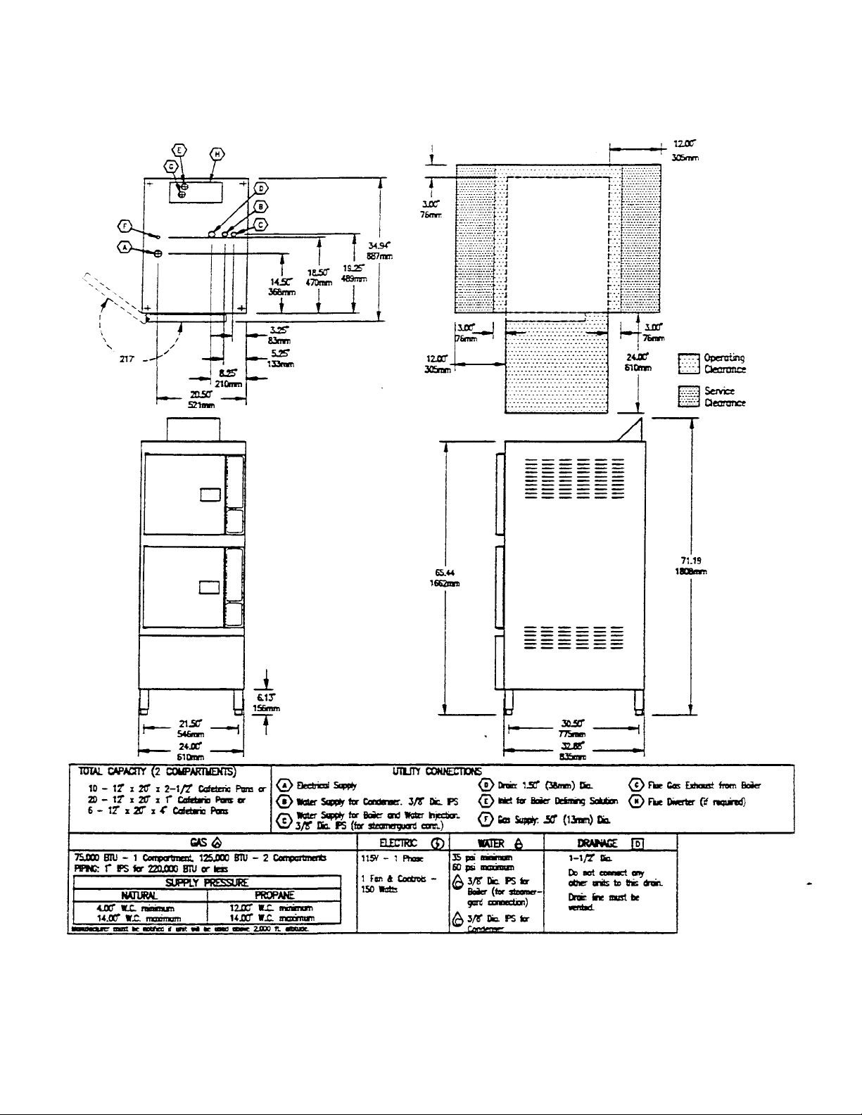
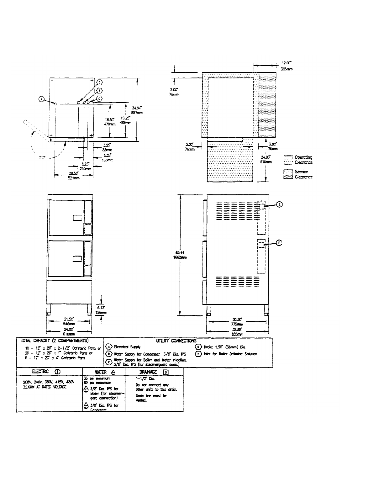
Page 12 Chapter 2, SteamCraft 10 Service Manual Models 24-CGA-10, 24-CGP-10, 24-CEA -10, 24-CEP-10
Figure 2-2- SteamCraft 10 Dimensions and Clearances
Model 24-CGA-10 (Sheet 1 of 4)
Printed 3/93 Cleveland Range, Inc.
Page 21
Models 24-CGA-10, 24-CGP-10, 24-CEA-10, 24-CEP-10 SteamCraft 10 Service Manual, Chapter 2 Page 13
Figure 2-2- SteamCrafi 10 Dimensions and Clearances
Model 24-CGP-10 (Sheet 2 of 4)
Cleveland Range, Inc. Printed 3/93
Page 22
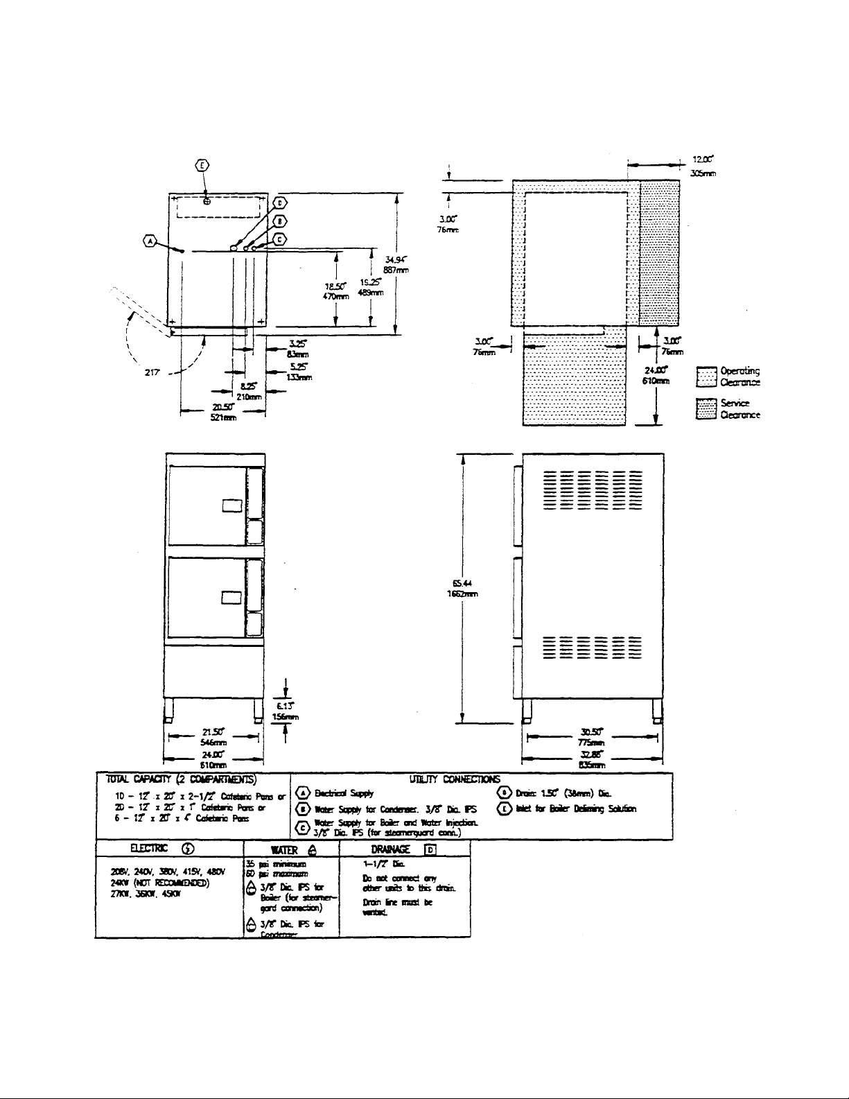
Page 14 Chapter 2, SteamCraft 10 Service Manual Models 24-CGA-10, 24-CGP-10, 24-CEA-10, 24-CEP-10
Figure 2-2- SteamCraft 10 Dimensions and Clearances
Model 24-CEA-10 (Sheet 3 of 4)
Printed 3/93 Cleveland Range, Inc.
Page 23
Models 24-CGA-10, 24-CGP-10, 24-CEA-10, 24-CEP-10 SteamCraft 10 Service Manual, Chapter 2 Page 15
Figure 2-2. SteamCraft 10 Dimensions and Clearances
Model 24-CEP-10 (Sheet 4 of 4)
Cleveland Range, Inc. Printed 3/93
Page 24

Page 16 Chapter 2, SteamCraft 10 Service Manual Models 24-CGA-10, 24-CGP-10, 24-CEA-10, 24-CEP-10
Softened, Treated, or Filtered Water
Do not use softened or chlorinated water in the SteamCraft 10 steam
generator- If the water supply is treated or softened either by the
water company or on the premises, it may contain chlorine or various
salts. These additives are damaging to the SteamCraft 10 steam
generator. Salts used to soften water cause rapid scale buildup, and
increased corrosion.
Some water treatment plants kill bacteria in the water by adding
chlorine. Chlorinated water is actually dilute hydrochloric acid. It is
very damaging to the SteamCraft 10. When heated in the steam
generator, chlorinated water rapidly dissolves generator walls and
heater elements. In extreme cases, poisonous and highly corrosive
chlorine gas is released in the steam generator.
Installing a high volume water filtering system such as the
SteamerGard removes most of the salts used for water softening.
Contact a local water treatment specialist or the local water company
for assistance with chlorinated water.
Water Supply System
Select a water supply system that fulfills the requirements listed in
Table 2-2. The supply must provide a minimum dynamic pressure of
35 psi (2.4 kg/cm2) and a maximum static pressure of 60 psi (4.1
kg/cm2). Refer to page 24 for detailed pressure and fitting
requirements, and recommended plumbing layouts.
• Always connect a cold water supply to the SteamCraft 10 water
supply lines. DO NOT USE HOT WATER. The SteamCraft 10 will
not function properly or within design safety limits if hot or warm
water is supplied to the condenser water connection.
• If analysis shows that the supply water is within the required limits, a
single line water system can be installed. A single water line system
is illustrated in Figure 2-10 on page 25,
• If analysis shows that the supply water is NOT within the required
limits, install a SteamerGard water treatment system. Figure 2-11
on page 25 illustrates a treated water supply arrangement.
• If analysis shows that the supply water is NOT within the required
limits, and it is NOT possible to install a SteamerGard water
treatment system;
plan on increasing the frequency of maintenance, cleaning, and
descaling beyond that recomme nded in the maintenance schedule
(Chapter 4).
Page 25

Models 24-CGA-10, 24-CGP-10, 24-CEA-10, 24-CEP-10 SteamCraft 10 Service Manual, Chapter 2
Selecting The Operating Location
For safe and efficient operation, observe the following criteria when selecting an
operating location for the Steam Craft 10 Steamer.
1. Do not install these units in areas where combustibles are stored or may
accumulate. The surrounding area must be clear of combustibles, including the
space under the unit.
2. Do not locate the SteamCraft 10 directly over a floor drain used for:
draining hot condensate from this or any other appliance. The drain must be
outside the body of the unit.
3. A proper air supply for combustion and ventilation air is critical for safe,
efficient operation of SteamCraft 10 Steamers. The area around the steamer
must have adequate ventilation for gas-fired appliances.
4. The back panel and both side panels have vents for combustion and ventilation
air. Do not block these air vents. Do not install any heat producing equipment
near the air vents of the unit.
WARNING
All clearance requirements above, below, and
around the unit are the same for non-combustible
locations as for combustible locations.
5. The dimension drawings (Figure 2-2) specify all dimensions and clear ances
required for proper operation and service of each SteamCraft 10 Steamer
covered in this manual. Maintain at least a 3-inch operating clearance at the
sides of the unit, and at least a 3-inch clearance at the back. Do not store articles
on top of the unit.
6. The lower from and right side panels of the unit are the service access panels.
Select an operating location that allows a minimum 12-inch clearance for
service access through these panels.
7. Installation of an exhaust hood over the unit may be required by local, state,
and/or national codes. Refer for Exhaust Hood Requirements - All Models on
page 10. If the SteamCraft 10 cannot be installed under an existing hood, check
the exhaust hood venting requirements for a suitable hood over the operating
location.
8. The location selected must be capable of supporting the operational weight of
the SteamCraft 10, including the weight of water and food. The SreamCraft 10
Steamer operating weights are listed on the dimension drawings.
9. The Steam Craft 10 must be level both front for back and side to side. Select an
operating surface that is level enough for allow leveling the unit without
extreme adjustment of the legs.
Page 26
Page 18 Chapter 2, SteamCraft 10 Service Manual Models 24-CGA-10, 24-CGP-10, 24-CEA-10, 24-CEP-10
INSTALLATION INSTRUCTIONS
After selecting the operating location, the SteamCraft 10 can be unpacked,
positioned, and installed. After Final Setup and Checkout, the SteamCraft 10 will
provide years of reliable operation.
CAUTION
Malfunctions and equipment damage may result from improper
mounting. Malfunctions and/or damage resulting from
improper mounting are not covered by the equipment warranty.
The SteamCraft 10 MUST BE LEVEL BOTH FRONT TO
BACK AND SIDE TO SIDE in all mounting arrangements.
Equipment damage will result from shifting the SteamCraft 10
more than 10° out of level while power is turned on. The unit
must be level front to back and side to side.
U npacking and Inspection
1. Before unpacking the shipping carton, visually inspect it for damage.
• If the shipping carton appears damaged, do not open the carton. Refer to the
Shipping Damage Instructions on page 19.
• If the shipping carton is undamaged, proceed with step 2.
2. Slit the four corners of the carton and peel carton sides away from the SteamCraft
10. The slide racks are shipped in separate packing inside the cooking
compartment. Be careful not to damage or throw these racks away.
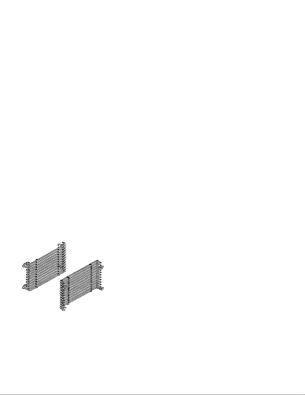
3. Remove the slide rack carton from the cooking compartment. The pack age
contains four slide racks (two for each cooking compartment) as illustrated in
Figure 2-3.
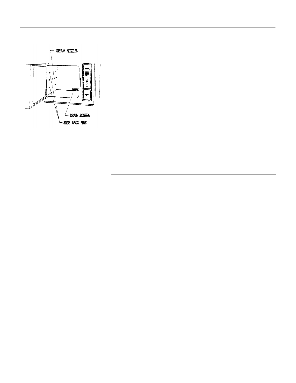
4. Open both cooking compartment doors. Several pre-assembled parts can be seen
inside each cooking compartment. Refer to Figure 2-4, and verify that the Drain
Screen, Steam Nozzles, and Slide Rack Mounting Pins are installed.
5. Inspect the SteamCraft 10 and parts for damage or loss.
• If you discover or suspect shipping damage or loss, refer to the Shi pping
Damage Instructions.
• If all items are accounted for and undamaged, place the packaged slide racks
inside the cooking compartments, and proceed to Position and Level the
SteamCraft 10.
Figure 2-3. Slide Racks
Page 27
Models 24-CGA-10, 24-CGP-10, 24-CEA-10, 24-CEP-10 SteamCraft 10 Service Manual, Chapter 2 Page 19
Shipping Damage Instructions
If shipping damage to the SteamCraft 10 is discovered or suspected, observe the
following guidelines in preparing a shippi ng damage claim.
• Write down a description of the damage or the reason for suspecting damage as
soon as it is discovered. This will help in filling out the claim forms later.
• As soon as damage is discovered or suspected, notify the carrier who delivered
the shipment.
• Arrange for a carrier representative to examine the damage.
• Fill out all appropriate claims forms and have the examining carrier sign and date
each form.
Figure 2-4. Pre-assembled Pans
Position and Level The
SteamCraft 10
NOTE: If ther e is not enough room to work on the drain, electrical. and water lines
with the SteamCraft 10 in place, skip this procedure until they are
completed. While preparing the utility lines, protect the SteamCraft 10
as described on page 10. After the lines are prepared, position and level
the SteamCraft 10, then connect the utility lines.
Adjustable Leveling Legs
The supporting legs of the SteamCraft 10 Steamer are 6-inches long when the
adjustable feet are fully retracted. This provides the minimum 6-inch space below
the unit required by NSF sanitary standards. The adjustable feet can be extended
approximately 2 inches to provide a means of leveling the SteamCraft 10.
Positioning and Leveling
1. Check that all Unpacking and Inspection tasks are complete.
2. Thoroughly clean the floor area that will support the SteamCraft 10.
3. Using a level, determine and mark the highest corner of the floor area that will
support the leveling legs.
WARNING
INJURY AND EQUIPMENT DAMAGE could result from
improper lifting. Refer to the appropriate di mension drawing
and check the weight of the unit being installed. Use enough
workers with experience lifting heavy equipment to place the
SteamCraft 10 on the supporting surface.
Page 28
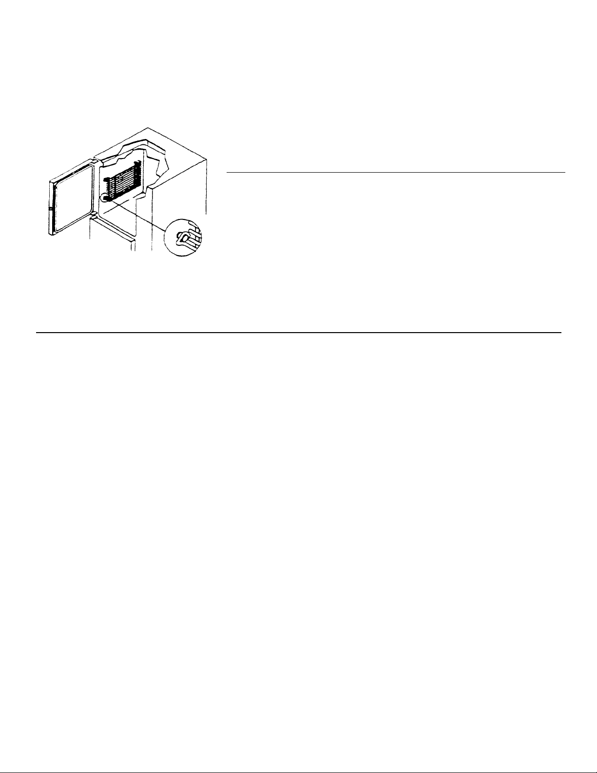
Figure
2-5.
Slide Rack Installation
I
nstall and Connect the Free Air
Page 20 Chapter 2, SteamCraft 10 Service Manual Models 24-CGA-10, 24-CGP-10, 24-CEA-10, 24-CEP-10
4. Move the SteamCraft 10 into position.
5. Check the adjusting foot of the leg in the highest corner (marked in step 3). The
foot should be fully retracted and provide a 6-inch clearance under the unit.
6. Using a level, adjust the other three legs until the Steam Craft 10 is level both front
to back and side to side.
7. After the Steam Craft 10 has been positioned and leveled, install the slide racks as
described below.
Install Slide Racks
1. Refer to Figure 2-5. There are two slide racks for each cooking compartment. Each
rack has four loops: two at the top and two at the bottom. Hold the slide rack so
the ends of the hanger loops point down, as shown in the figure.
2. Slide one rack into the compartment with loops toward the compartment wall and
mounting pins.
3. Hook the loops over the top and bottom pins.
4. Repeat steps 1 through 3 for each of the other racks.
Vented Drain Lines
The drain outlet must be free air vented to equalize the pressure in the Steam Craft 10
Steamer with the atmosphere. Generating steam causes pressure to increase in the
unit; cold water flow into the condenser creates a vacuum (low pressure) in the
condenser. Without a free air vent, either high or low pressure in the compartment
will cause malfunction or damage.
• Pressure build up in the steamer will cause steam and hot water leakage around the
door.
• A vacuum will implode the steamer and cause permanent physical damage.
Refer to Figure 2-6, and the dimension drawings (Figure 2-2). The drain outlet (D)
discharges exhaust steam and hot condensate from the steamer. The drain exhaust
vent and a 1-inch minim um clearance between the drain opening and floor drain
provide the SteamCraft 10 Steamer with free air venting.
Furnishing and installing the drain lines and fittings is the responsibility of the owner
and/or installer. Figure 2-6 illustrates a drain layout recommended by Cleveland
Range. Observe the following instructions to determine the pipe size, the number of
fittings required, and the layout of the drain line.
Page 29
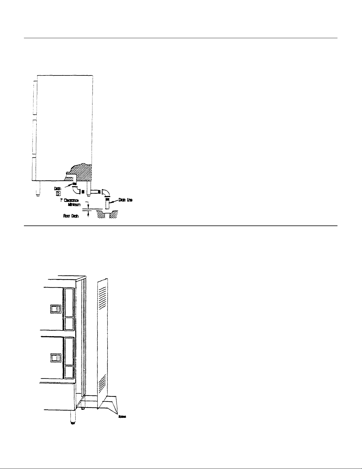
Figure
2-6.
Drain Layout and Connections
Models 24-CGA-10, 24-CGP-10, 24-CEA-10, 24-CEP-10 Page 21 SteamCraft 10 Service Manual, Chapter 2
WARNING
DEATH, INJURY, AND EQUIPMENT DAMAGE
could result from improper installation of the drain
outlet lines.
Improper installation of these lines could void the
SteamCraft 10 Steamer warranty. The following
restrictions are critical to the safety of personnel and
equipment, and must not be violated under any
circumstances.
Do not connect the drain line into PVC pipe, or any
other drain material that cannot sustain 180° F.
Do not connect drains from any other equipment to the
SteamCraft 10 Steamer drain line.
Do not connect the drain outlet extension line directly
to a floor drain or sewer line.
1. The drain lines must be installed in compliance with local, state, and national
utility, construction and sanitation codes; the most prominent of which are listed
in the Installation Policies section below
2. The floor drain receiving the hot condensate from the Steam Craft 10 must not be
located under the body of the unit. Steam rising from the drain up into the unit
body will adversely affect operation, cooling air ventilation. and may cause
corrosion on some of the electrical contacts. Improper location of this drain will
seriously reduce warranty coverage.
3. The total length of pipe and number of bend fittings required to reach the open
drain determines the pipe size used to extend the drain line to an open drain.
• If the drain outlet extension requires six feet or less of pipe, and no more than
two elbows are required, use 1.5-inch pipe and fittings.
• If the drain outlet extension requires six to twelve feet of pipe, or requires three
or more elbows, use 2-inch pipe and fittings.
4. The drain line must have a gravity flow from the Steam Craft 10 Steamer drain
outlet to the floor drain Do not install a trap in the drain line.
5. Free air venting requires a minimum of one inch clearance between the end of the
drain line and the top of the floor drain.
6. Do not connect the steamer drain to drains or plumbing of any other equipment. If
drains of two or more units are connected together.
• Low pressure can develop, causing an implosion and physical collapse of the
steamer.
• Drainage from another unit can flow back into a cooking compartment of the
steamer.
Figure 2-7. Access Panel Removal
Page 30

Figure 2
-
7
Exhaust Hood Ventilation All
SteamCraft 10's with gas
-
fired steam generators have a
n exhaust hood (H.
Figure 2
-
Furnishing and installing the electrical power lines, switches, fuse boxes, connectors
Page 22 Chapter 2, SteamCraft 10 Service Manual Models 24-CGA-10, 24-CGP-10, 24-CEA-10, 24-CEP-10
Models
7. Refer to
to the 1.5-inch drain pipe connection (D) inside the Steam Craft 10.
8. When assembling the drain pipes and fittings, apply a hardening type pipe sealant
to the threads, and thread them together FINGER TIGHT ONLY. DO NOT USE
A WRENCH.
2) which covers the Gas Flue port (G) on top of the unit. In addition to the required
venting of gas-fired equipment, some state and local codes require the venting of
steam generating equipment.
1. The SteamCraft 10 gas flue (G ) must be vented in compliance with all local, state,
and national codes for venting gas-fired appliances. Steam venting must comply
with the state and local codes where applicable.
2. The exhaust hood must be sized for the cumulative ventilation requirem ents of all
gas -fired appliances in the area, as well as to the SteamCraft 10.
3. Do not connect the gas flue directly to a forced draft exhaust system or canopy.
Excess draft through the flue reduces the oven's efficiency and may affect cooking
times.
4. If an existing exhaust hood cannot be used, a new one should be con-structed over
the SteamCraft 10. The Dimensions and Clearances Draw -ing (Figure 2-2)
contains the dimensions, gas flow, and BTU per hour data required to calculate
the minimum required hood dimensions and minimum ventilation capacity
(c.f.m).
. Remove the right side access panel and connect the drain line
Install Electric Power Lines
and accessories is the responsibility of the owner and/or installer. Figure 2-8
illustrates an electrical layout recommended by Cleveland Range. When installing the
electrical power lines and accessories, observe the following instructions.
1. In the United States, install the electrical power lines in accordance with local
codes and/or the National Electric Code, ANSI/NFPA No. 70-1990 (USA).
2. In Canada, install the electrical power lines in accordance with local codes and/or
the Canadian Electrical Code, CSA Standard C22.1 (Canada).
3. Install the proper size, disconnect switch, circui t breaker or fuses, and wire and
conduit to conform to all local codes and the national codes cited above. See
Table 2-3 for wire requirements.
4. Install a separate disconnect switch and fuses or breakers sized to meet the line
amps required by the Steam Craft 10 (see Table 2-3). The fuses or breakers may
be an integral part of the disconnect switch or in a separate fuse box. Install the
disconnect switch for easy access as needed for daily startup and shutdown.
Page 31

Connect Electrical Line
AMPS
AMPS
Refer to Table
4-1.
and identify th
e
electrical schematic diagram th
at applies
Models 24-CGA-10, 24-CGP-10, 24-CEA-10, 24-CEP-10 SteamCraft 10 Service Manual, Chapter 2 Page 23
Figure 2-8. Recommended Electrical Layout
5. There should be a sufficient length of flexible conduit between the SteamCraft 10
connector and the wall so the unit can be moved for service
6. Each steamer must be electrically grounded by the installer in accordance with the
National Electric Code, ANSI/NFPA No. 70-(latest edition).
7. The characteristics of the electric power supply must match the power
requirements specified on the SteamCraft 10 product identification plate. The
plate is located on the left side panel, in the lower right corner, as detailed in
Figure 2-2.
Table 2-3. Minimum Wire Requirements
VOLTS KILOWATTS
3 Phase
208 32.6 92 115 0
220 27.4 73 91 1
240 32.6 80 100 1
440 27.4 36 45 6
480 32.6 40 50 6
*Use solid copper wire rated for 75°C, wet location.
SERVICE
WIRE
SIZE*
to the SteamCraft 10 model being installed. Connect the electrical lines to the
terminal block inside the right side access panel as described below.
1. Verify that the main disconnect switch is in the OFF position.
2. Remove the right side access panel by removing the three screws
(Figure 2-7) that hold it in place. Save the screws.
3. Refer to the connection diagram in Figure 2-9, and connect the wires to the
terminal block and ground connector accordingly.
Page 32

Figure
2-9.
Electrical Connections
Install Water Supply Lines
Furnishing and plumbing the water supply lines is the responsibility of the
Page 24 Chapter 2, SteamCraft 10 Service Manual Models 24-CGA-10, 24-CGP-10, 24-CEA-10, 24-CEP-10
4. The steamer must be electrically grounded by the installer in accordance
with the National Electric Code, ANSI/NFPA No. 70-(latest edition).
5. If no further work inside the side panel is required at this time, such as
plumbing and leak checks, secure the side panel with the three mounting
screws (Figure 2-7). Do not turn power ON at the main disconnect switch
until power is required for component or operational testing
owner and/or installer. This section illustrates plumbing layouts recommended
by Cleveland Range. When installing water supply lines, observe the following
instructions.
1. The Steam Craft 10 has two 3/8-inch IPS fittings for connecting the steam
generator and condenser/blowdown water supply lines. These fittings are
detailed as C and B in Figure 2-2.
2. Always connect a cold water supply to both water supply lines. DO NOT
USE HOT WATER. The steamer will not function properly or within
design safety limits if hot or warm water is supplied to either the condenser
connection or the steam generator fill connection.
3. Do not connect the SteamCraft 10 to a softened or treated water supply
which adds chlorine or chloride salts to the water. Refer to Softened,
Treated, or Filtered Water on page 16 for details.
4. Supply water must have a minimum dynamic pressur e of 35 psi (2.4 kg/cm )
and a maximum static pressure of 60 psi (4.1 kg/cm2). Water pressure
greater than 60 psi will cause damage TO the solenoid valves. Local water
pressure can be 100 psi or more. If possible, check supply pressure at nonpeak demand time. A local water company can assist in this check. If static
pressure exceeds 60 psi, a pressure regulator must be installed in the supply
lines. For best results, set the regulator for 50 psi dynamic pressure.
Page 33

Models 24-CGA-10, 24-CGP -10, 24-CEA-10, 24-CEP-10 SteamCraft 10 Service Manual, Chapter 2 Page 25
5. Refer to the recommended plumbing layouts in Figures 2-10 and 2-11 and install
the water supply lines and fittings in accordance with all local and national
codes. Pay particular attention to the following requirements and
recommendations.
a. When installing a water supply system without a SteamerGard, Cleveland
Range recommends the plumbing layout illustrated in Figure 2-10. This is a
single water line from the main cold water supply to the tee just outside the
SteamCraft 10. The two separate lines from the tee to the steam generator and
condenser/blowdown connections are comparatively short.
b. When installing a water supply system with a SteamerGard. Cleveland Range
recommends the plumbing layout illustrated in Figure 2-11. Note the following
details:
• This is a single water line from the main cold water supply to the tee just
before the SteamerGard. The two separate and comparatively short lines
run from the tee to the SteamerGard intake connection and from the tee to
the SteamCraft 10 condenser/blowdown connec-tion.
• The water supply to the condenser connection can be untreated.
• The treated water supply connects to the steam generator fill connec -
tion.
Figure 2-11. Treated Water Supply Arrangement
Page 34

Connect Water Supply Lines
c. Whether installing a treated or untreated water supply system, use the
General Connection Requirements
Page 26 Chapter 2, SteamCraft 10 Service Manual Models 24-CGA-10, 24-CGP-10, 24-CEA -10, 24-CEP-10
following water line sizes.
• For the two lines between the Steam Craft 10 and the tee use 3/8-inch
IPS water supply lines to match the 3/8-inch compression fittings
mounted on the bottom panel of the SteamCraft 10.
• For the single line between the tee and the main cold water supply,
use 1/4-inch to 5/8-inch IPS water supply lines. If lines larger than
5/8-inch are used in this segment, a pressure regulator must be
installed before the tee, to maintain the pressure specified in step four.
d. Install a manual water valve between the main cold water supply line
and the SteamCraft 10 lines.
e. The National Sanitarian Foundation (NSF) requires installation of a
check-valve in all supply lines in accordance with and as required by
local plumbing codes.
f. At the points indicated in the recommended plumbing layouts, install a
40-mesh water strainer of the type and construction illustrated in Figure
2-12. A strainer is provided with the Steam Craft 10.
Figure 2-12. Water Strainer Assembly
Figure 2-13. Water Strainer Installation
4. Construct all supply lines up to the point of installing the strainer(s)
illustrated in the recommended plumbing layouts. Flush the water supply
lines before connecting the strainer(s).
• If the remaining water supply lines and/or SteamerGard are not
immediately installed and connected after flushing, temporarily cap the
water supply lines.
• If the final installation and connections are performed immediately, refer
to the connection instructions in the SteamerGard manual, and Connect
Water Supply Lines, following.
The water supply connections are located unde r the SteamCraft 10, as shown
in Figure 2-2. Connect the water supply lines to the Steam Craft 10 by
following both the general connection requirements and those requirements
specific to the type of supply system, either untreated water supply (Figure 2-
10) or water supply treatment system (Figure 2-11).
1. Apply pipe dope or teflon tape to any threaded connection.
2. Flush the water supply lines before connecting the strainers), and again
before connecting the lines. to the SteamCraft 10 connections.
3. When installing water strainer(s), use a strainer with a 40 mesh screen as
illustrated in Figure 2-13.
• Make sure the arrow on the strainer body points in the direction of flow
i nto the steamer.
• Install the strainer so the access nut points down.
4. If incoming line pressure exceeds 60 psi static pressure, install a pressure
regulator to maintain the SteamCraft 10 pressure requirements specified in
Install Water Supply Lines (pa ge 24).
Page 35

Testing Water Supply Lines
Treated Water Connection (With SteamerGard)
Install and Connect Gas
Untreated Water Connection (Without SteamerGard)
Models 24-CGA-10, 24-CGP-10, 24-CEA-10, 24-CEP-10 SteamCraft 10 Service Manual, Chapter 2 Page 27
1. Refer to Figure 2-10. Verify that a suitable check valve is installed according to
NSF and local codes.
2. Look at the flow indicating arrows on the strainer and check valve and verify that
flow is toward the steamer.
3. Install the tee and connecting lines- Flush these lines before connecting them to
the water supply fittings on the steamer.
1. Verify that the SteamerGard water treatment system has been installed according
to the SteamerGard installation manual. The 40-mesh strainer supplied with the
SteamerGard must be installed at the SteamerGard water inlet.
2. Refer to Figure 2-11. Verify that suitable check valves are installed according to
NSF and local codes. The condenser line check valve should be installed
between the tee and the steamer. The steam generator line check valve should be
installed between the SteamerGard and the steamer.
3. Look at the flow indicating arrows on the strainers and check valves. Verify that
flow is toward the steamer.
4. Install the connecting lines and flush them before connecting them to the water
supply fittings on the steamer. Be sure the line from the Steamer Gard water
treatment system connects to the steam generator fitting on the SteamCraft 10.
Supply Lines
1. Check all connections for proper tightness. Remove the side panel to inspect
water connections inside the steamer (Figure 2-7).
2. Open the water supply valves.
3. Check all lines and connections for leakage, both inside and outside the steamer.
4. If no other inspections are being made at this time, replace the right side access
panel.
Furnishing and installing the gas supply lines, valves, regulators, and accessories is
the responsibility of the owner and/or installer. When installing the gas supply lines
and accessories, observe the following instructions.
1. Install the gas supply lines in accordance with local codes and/or the National
Fuel Gas Code, ANSI Z223.1-(latest edition).
2. Refer to Figure 2-14 for Cleveland Range recommended layout of the gas supply
lines. Refer to Figure 2-2, Dimensions and Clearances for pressure data and
connection locations.
Page 36

Page 28 Chapter 2, SteamCraft 10 Service Manual Models 24-CGA-10, 24-CGP-10, 24-CEA-10, 24-CEP-10
Figure 2-14. Recommended Gas Supply Line Layout
Leak-Testing Gas
Supply Lines
• On Atmospheric models (24-CGA-10), use 1/2-inch IPS gas supply pipe
and fittings.
• On Pressure models (24-CGP-10), use 3/4-inch IPS gas supply pipe and
fittings.
3. Install a manual shut off valve between the gas supply line and the
SteamCraft 10 gas connection (F on Figure 2-2)
4. Install a sediment trap (drip leg) in the gas supply line, then connect the
gas supply piping to the steam generator gas valve piping. In order to
protect the automatic gas control valve from condensation, the drip leg
should be close to the SteamCraft 10 gas connection.
5. If natural gas pressure exceeds 14" water column, a pressure regulating valve must
be installed in the gas supply plumbing to reduce the pressure to within the limits
specified in Gas Supply Requirements, on page 10.
6. If LP gas is supplied, use a gas pipe joint compound which is resistant to
LP gas. Refer to Figure 2-2 and note the pressure limit specified for LP
gas.
The gas lines and burner control connections should be inspected for proper
installation, and tested for leaks and proper operation:
• At Initial Installation
• As pa rt of regular maintenance procedures.
• As the first step in troubleshooting.
• After service or repair, the components affected should be inspected and
tested for leaks and proper operation.
Page 37

Models 24-CGA-10, 24-CGP-10, 24-CEA-10, 24-CEP-10 SteamCraft 10 Service Manual, Chapter 2 Page 29
WARNING
FIRE OR EXPLOSION HAZARD
LEAKING GAS CAN CAUSE FIRE OR EXPLOSION
WITH PROPERTY DAMAGE, INJURY, OR LOSS OF
LIFE. If the installer smells gas, or suspects there is a gas
leak, immediately refer to the posted gas leak instructions.
The posted instructions are provided by the local gas supplier.
and supersede any other instructions. Until the leak is
stopped, observe the following precautions in addition to the
posted instructions.
• Do not light or start any appliance.
• Do not touch any electrical switch.
• Do not use any phone in the building.
• Immediately call the gas supplier from a phone away from the bui lding
Follow the gas supplier's instructions.
• If the gas supplier cannot be reached, call the fire department.
Pressure Testing The Gas Supply Lines
Do not permanently supply gas to these lines until they have been tested. When
testing these lines observe the following.
1. A gas lines and fittings assembled during installation are outside of the
SteamCraft 10. Check these connections for proper tightness.
2. Prepare the Steam Craft 10 valves and connections for the test pressure being
used. The same pressure criteria apply when testing lines prior to the manual
gas shut-off valve.
• The appliance and its individual shut-off valve must be disconnected from the
gas supply piping system during any pressure testing of that system at test
pressures in excess of 14" water column (1/2 psi or 3.45 kPa).
• The appliance must be isolated from the gas supply piping system by closing
its individual manual shut-off valve during any pressure testing of the gas
supply piping system at test pressures equal to or less than 14" water column
(1/2 psi or 3.45 kPa).
3. Refer to Figure 2-14, and open the main shut-off valve for the steamer gas supply
line.
4. Test the pipe joints for leaks with soap and water solution.
• Paint pipe joints with rich soap and water solution.
• Bubbles indicate a gas leak.
• Tighten joints and/or replace component to stop gas leak.
• If you smell gas, turn off the main gas shut-off valve, and refer to Gas Leak
Instructions on page 43.
5. Reassemble any connections or piping disassembled in step 2. Repeat steps 3
and 4 to test these reassembled connections.
6. Close the main shut-off valve for the steamer gas supply line.
Page 38

Page 30 Chapter 2, SteamCraft 10 Service Manual Models 24-CGA-10, 24-CGP-10, 24-CEA-10, 24-CEP-10
Figure 2-15. Automatic Gas Valve
Bleed Air from the Gas Supply Lines
After the gas supply line is assembled, connected to the SteamCraft 10, and
pressure tested satisfactorily; bleed the air from the line. The SteamCraft 10
gas control module uses an intermittent gas pilot. The module sparks the pilot
igniter and sends gas to the pilot simultaneously. If the pilot flame sensor does
not detect pilot ignition within a few seconds, the control module stops both
pilot spark and gas flow. Bleeding the entire supply gas line through this type of
gas control system may take quite a long time. To save time, bleed the air
through a loosened fitting. Bleed the gas supply line by the following
procedure.
1. Turn off electrical power to the SteamCraft 10 at both the panel ON/OFF
switch (Figure 2-16), and the main disconnect switch (Figure 2-8, Rec ommended Electrical Layout).
2. Remove the left side access panel by removing the three mounting screws.
Save the screws.
• Verify that the automatic gas valve wiring connections are clean and tight.
• Verify that the manual ON/OFF valve of the automatic gas valve is in the
ON position (Figure 2-15).
3. If the main gas valve is too far from the unit for one man to both bleed the
line and operate the valve, arrange for an assistant to operate the valve.
4. Use the union fitting located just ahead of the gas valve as the bleed point.
This will minimize the amount of air remaining between the bleed point and
the automatic gas valve after bleeding the line. If it is not possible or
convenient to use this union fitting, select another fitting close to the
SteamCraft 10 automatic gas valve. To minimize the amount of air
Page 39

Models 24-CGA-10, 24-CGP-10, 24-CEA-10, 24-CEP-10 SteamCraft 10 Service Manual, Chapter 2 Page 31
remaining between the bleed point and the automatic gas valve, select a fitting
as close as possible to the valve. If the drip leg is close enough to the Steam
Craft 10, it may be used as an alternate bleed point.
5. Loosen the fitting enough to allow gas to escape. Open the main gas valve and
bleed the trapped air out of the gas supply line. Retighten the fitting.
6. Test the pipe joint for leaks with soap and water solution.
• Paint pipe joint with rich soap and water solution.
• Bubbles indicate a gas leak.
• Tighten joints to stop gas leak.
7. Install the left side access panel on the Steam Craft 10.
8. Leave the electrical power OFF at both the main disconnect switch and the
control panel ON/OFF switch.
9. The SteamCraft 10 is now ready for operational testing.
• If this test is part of initial installation, perform the Burner Ignition Test
before performing the Operating Tests.
• If this is part of component repair, perform the Burner Ignition Tests next If
the unit passes, it is ready to resume normal cooking operations
WARNING
DO NOT TRY TO LIGHT THE BURNERS OR PILOT
WITH A FLAME. The SteamCraft 10 has an electronic
ignition system which automatically lights the pilot and burners, senses the flame, and controls gas flow. This provides
precise burner control, safety ignition, and shutdown features.
DEATH. INJURY OR EQUIPMENT DAMAGE may result
from an improperly adjusted gas control and ignition system.
Do not alter any adjust ments on this electronic control or
solenoid valve. If adjustment is required, contact an
authorized service center. Cleveland Range is in no way
responsible for the operation or safety of this equipment if the
controller, valve, or igniter probes are adjusted by anyone
other than a Cleveland Range authorized service
representative.
Burner Ignition Test
(Gas-Fired Models Only)
This is a functional test of the intermittent pilot ignition system. Pilot/burner
ignition is completely automatic. The test consists of starting the unit and setting
the controls for generating steam. The ignition system will either light the pilot and
burners, or fail.
1. If not already done during prior installation and testing:
Page 40

Page 32 Chapter 2, SteamCraft 10 Service Manual Models 24-CGA-10, 24-CGP-10, 24-CEA-10, 24-CEP-10
a. Pressure test the gas supply lines as described in Pressure Testing Gas
Supply Lines.
b. Bleed trapped air from the gas supply lines as described in Bleed Air
From The Gas Supply Lines, above.
c. Check that the manual ON/OFF valve of the automatic gas control
valve is in the ON position.
d. Turn the main manual gas shut-off valve to the ON position.
2. Turn ON the electrical power to the SteamCraft 10 at the main disconnect
switch.
NOTE: When initial power is supplied to the SteamCraft. 10 with the
ON/OFF switch in the OFF position, a 3-minute blowdown
cycle starts. This blowdown cycle stops when the ON/OFF
switch is changed to the ON position.
3. For Atmospheric Models Only (24-CGA-10 and 24-CEA-10): Turn
ON the electrical power to the SteamCraft 10 at the control panel ON/OFF
switch.
a. Water begins filling the steam generator. The preheating circuits are
energized but the burners do not light until water reaches the safety
level sensor.
b. After 5 to 7 minutes, water reaches the safety level sensor and the
burners light with a distinctive sound.
• If the burners light within 7 minutes of turning the unit ON, the igniter
control s are functioning. End this test procedure here.
• If the burners do not light within 9 minutes of turning the unit ON,
there may be air in the gas supply lines. Proceed to step 5.
4. For Pressure Models Only (24-CGP-10 and 24-CEP-10): Turn ON the
electrical power to the SteamCraft 10 at the control panel ON/OFF
switch.
a. The red indicator the switch lights and water fills the steam generator.
b. After about 5 minutes, the amber indicator the STEAM switch lights.
c. When the amber light turns on, pr ess the STEAM switch on the control
panel. The burners should light with a distinctive sound.
• If the burners light within one minute of pressing the Steam switch,
the igniter controls are functioning. End this test procedure here.
• If the burners do not light within one minute of pressing the Steam
switch, there may be air in the gas supply lines. Proceed to step 5.
5. Turn off electrical power to the SteamCraft 10, at both the panel ON/OFF
switch (Figure 2-16), and the main disconnect switch (Figure 2-8, Recommended Electrical Layout).
NOTE: When the burners fail to ignite, a safety circuit in the igniter
control de -energizes the system and closes the automatic gas
valve. The safety circuit resets when the SteamCraft 10 is
turned OFF and turned back ON.
6. Refer to Bleed Air from the Gas Supply Lines, and bleed any trapped air
from the gas supply lines.
Page 41

Final Setup and Checkout
Installation Checks
Models 24-CGA-10, 24-CGP-10, 24-CEA-10, 24-CEP-10 Page 33 SteamCraft 10 Service Manual, Chapter 2
7. Repeat steps 2 through 6 no more than three times. If the burners do not
light after the third attempt, call a Cleveland Range authorized service
representative to adjust the burner controls.
8. Turn off electrical power to the Steam Craft 10, at both the panel ON/OFF switch
(Figure 2-16), and the main disconnect switch (Figure 2-8, Recommended
Electrical Layout).
The Final Setup and Checkout procedures prepare a recently installed or repaired
SteamCraft 10 for operation. The procedures check proper electrical, gas, water,
and drain connections to the SteamCraft 10, and verify basic steamer operation.
Read through all pans of this procedure before starting.
CAUTION
Equipment damage and faulty operation will result if the
gas, water, or electrical supplies fall below requirements.
This may be caused by other equip ment on the same
supply lines. During all tests, adjustments, and inspection
of the SteamCraft 10, turn on all equipment drawing on
the same utility supply lines.
Proper operation of the SteamCraft 10 is dependent upon proper
installation.Performing the following checks after installation could avoid
unnecessary service calls.
1. Refer to the appropriate dimension drawing and verify that the specified
clearances are met
2. Verify that the unit is level front to back and side to side.
3. Check inside each cooking compartment for proper installation of the drain
screen, slide racks, and door gasket assembly. Be sure the drain is not blocked.
4. Clean the protective plastic film off the outside of the Steam Craft 10.
5. Refer to the Installation Check List on page 8, and verify that each task has been
completed in accordance with the referenced paragraphs. Pay particular attention
to:
• Voltage Requirements and Electrical Connections
• Water Quality and Pressure Requirements
• Free Air Drain Layout and Venting
• Gas Supply Pressure Requirements (if appl icable)
• Exhaust Hood Venting (if applicable)
6. Refer to Figure 2-8, and Table 2-3, and verify installation of proper size fuses or
breakers.
7. Check that the water supply valves are open.
Page 42

Operating Tests
Page 34 Chapter 2, SteamCraft 10 Service Manual Models 24-CGA-10, 24-CGP-10, 24-CEA-10, 24-CEP-10
8. If using a SteamerGard water treatment system, refer to the SteamerGard
manual and start the system. Check that all valves between the SteamerGard and the SteamCraft 10 are open.
9. For gas fired models (24-CGA-10 and 24-CGP-10), turn on the main gas
supply valve only after the gas supply lines and the burner controls are
tested.
Perform these operating tests only after completing the Ins tallation Checks
and correcting any deficiencies. These operating tests consist of observing
various steamer functions in the MANUAL and the TIMED operating
modes. Read through all of the procedures before starting.
• The SteamCraft 10 has two cooking compartments and each compartment
has a separate control panel. The compartments can operate separately or
simultaneously. Throughout these tests, reference is made to only one
compartment control panel. Except when the instructions specify upper or
lower compartments, the controls of either or both panels can be used.
• The SteamCraft 10 control panels have either a Key Pad Timer or a Dial
Timer. The operating difference between the Dial and Key Pad Control
Panels is significant only in timed mode. To avoid confusion, a separate
Timer Testing procedure is provided for the Dial and Key Pad Control
Panels. In addition, SteamCraft 10 models 24-CGP-10 and 24-CEP-10
with pressure steam generators have a steam generator control panel.
The Key Pad Control Panel is shown in Figure 2-16, page 37. The
Timer Test for the key pad control panel starts on page 37.
The Dial Timer Control Panel is shown in Figure 2-18, page 38. The
Timer Test for the dial timer control panel starts on page 38.
Steam Generator Control Panel is shown in Figure 2-17, page 37 and
Figure 2-19, page 39.
Operating Test Preparation
1. Verify that electrical power to the SteamCraft 10, is turned OFF at both
the panel ON/OFF switch, and the main disconnect switch.
WARNING
Death, severe electrical shock or equipment damage
can result from touching any component inside unit
when main disconnect switch is in the on position.
Use extreme caution during testing with the access
cover removed.
2. Refer to Figure 2-7, and remove the right side access panel so the upper
and lower float assemblies are clearly visible.
Page 43

Models 24-CGA-10, 24-CGP-10, 24-CEA-10, 24-CEP-10 SteamCraft 10 Service Manual, Chapter 2 Page 35
Blowdown Inspection Procedure
1. The TIMED/MANUAL switch and TIMER settings are not significant while
the ON/OFF switch is in the OFF position.
2. With the panel ON/OFF switch turned OFF, turn on electric power to the
SteamCraft 10 at the main disconnect switch. The steamer will immedi ately
start an automatic, 3-minute blowdown cycle. During the automatic blowdown
cycle, the condenser and drain valves are fully open, while the steam generator
and float assembly are flushed with fresh water.
3- Stop the blowdown cycle before it is complete by setting the ON/OFF switch to
the ON position. This energizes the operating control circuits, the red ON/OFF
indicator lights, blowdown stops, and the steam gener ator fills with water.
4. Restart the blowdown cycle by setting the ON/OFF switch to the OFF position.
Observe the following functions.
a. Look at the top of the float control. There should be a steady flow of water
entering the top of the float chamber through the spray nozzle.
b. Look at the one inch vent gap between the steamer drain pipe and the floor
drain. A steady stream of water should be draining from the steamer.
c. After about 3 minutes, the cycle is complete. Check the two points listed
above; there should be no water flow at either point
Operating Test Procedures
1. Verify that electrical power to the SteamCraft 10 is turned OFF at the panel
ON/OFF switch, and turned ON at the main disconnect switch.
2. Set both upper and lower compartment TIMED/MANUAL switches to the
TIMED position.
3. Set both upper and lower compartment timers to zero minutes.
• For Key Pad Control Panels: The timer display is blank while the ON/OFF
switch is set to OFF. If the timer is not zeroed (00:00) when power is turned
on in step 4, press and hold the CLEAR key on the key pad control panel
until the timer is zeroed.
• For Dial Timer Control Panels: If the Timer is not zeroed, turn the dial
counter clockwise until it points to the 0 mark
4. Set the ON/OFF switch to the ON position. As the steam generator fills with
water, observe the following functions.
a. The red ON/OFF switch light turns on. The fill valve opens and water
begins to fill the steam generator.
b. After a few minutes, water appears in the bottom of the float cylinders as
the water level in the steam generator rises.
• Check that no water flows from the drain opening.
• Check for plumbing leaks.
5. When the water in the steam generator reaches a safe operating level
(approximately one inch from the bottom of the float cylinder):
Page 44

Page 36 Chapter 2, SteamCraft 10 Service Manual Models 24-CGA-10, 24-CGP-10, 24-CEA-10, 24-CEP-10
• For Atmospheric Models (24-CEA-10 and 24-CGA-10), the preheat
cycle starts. The steam generator heating components turn on to heat
the water to stand-by temperature. These components cycle off and on
to maintain the preheat temperature.
• For Pressure Models (24-CEP-10 and 24-CGP-10), the amber light in
the STEAM switch turns on. The heating components remain OFF and
do not turn ON until the STEAM switch is pressed.
a. Water continues to fill the generator and the water level in the float
continues to rise.
b. After a few minutes, the water in the steam generator reaches the
upper limit and the fill valve closes.
• The water level in the float cylinder stops rising about one inch from
the top of the cylinder.
• If the water level continues to rise above the top of the float cylinder,
have a qualified service representative check the float circuit.
6. For Pressure Models Only (24-CEP-10 and 24-CGP-10), momentarily
press the Steam switch.
a. The amber STEAM switch light turns off and the generator heating
components turn on. The steam generator begins to heat the water to
steam.
b. About 10 minutes after starting the steam generator heating compo-
nents, the Steam Pressure Gage on the steam generator control panel
(Figure 2-17) should register 10 psi.
7. Set the TIMED/MANUAL switch to MANUAL; the steaming cycle starts.
a. The condenser solenoid clicks open and condenser flow starts. After a
few seconds, a small stream of water flows from the drain pipe. If no
drain water flows, check that the condenser water supply valve is open,
and the lines are connected properly.
b. If the water level in the steam generator is above the safety limit (about
1-inch above the bottom of the float cylinder), the heater components
turn on.
c. Steam begins to enter and fill the compartment from the nozzles. A
small quantity of water may drip from the nozzles until steam clears the
lines.
8. With the SteamCraft 10 in Manual Cooking Mode, the unit will steam
continuously until turned off, or set to Timed Cooking Mode. Set both
upper and lower compartment control panels for MANUAL operation.
Steam should fill both cooking compartments. Check for steam leaks
around the door gaskets.
9. Observe the steam generator water float cylinders while steaming contin ues. As water steams out of the generator, the level in the cylinders should
fall and then rise as the system refills the generator. This water fill cycle
continues as long as the SteamC raft 10 continues to steam.
10. As the unit continues to steam in Manual Cooking Mode, test the no-water
safety circuit.
Page 45

Figure
2-17.
Steam Generator Controls
a. Close the Steam Craft
10
manual water supply valve. Observ
e the
.
Models 24-CGA-10, 24-CGP-10, 24-CEA-10, 24-CEP-10 SteamCraft 10 Service Manual, Chapter 2 Page 37
steam generator float cylinders while steaming continues.
b. As water steams out of the generator, the water level drops below the
safety level sensor. The Steam Craft 10 automatically shuts off.
c. Re-open the manual water supply valve. The Steam Craft 10
automatically re-fills the steam generator to the safety level, and
resumes steaming.
11. Leaving all control settings as they are, and allowing the Steam Craft 10
to continue steaming, advance to the Timer Test procedure for the unit
being tested.
• The Timer Test for the Key Pad Control Panel starts after this
procedure.
• The Timer Test for the Dial Timer Conrrol Panel starts on page 38
Timer Test Procedures - Key Pad Control Panel
1. Verify that electrical power and control settings are retained from the
previous Operating Test
• Main Disconnect Switch is ON.
• ON/OFF switch is ON.
• Both upper and lower TIMED/MANUAL switches are set to
MANUAL.
• Both upper and lower Timers are set to 00:00. If either timer is not
zeroed, press and hold the CLEAR ke y on the key pad control panel
until the timer is zeroed.
2. Set the TIMED/MANUAL switch to the TIMED position. With the
timer zeroed, the steam generating cycle stops.
a. The heating system turns off and condenser flow stops.
Figure 2-16. Key Pad Control Panel
Pressure Units Only
b. Steam stops entering the cooking compartment(s).
3. Open the cooking compartment door to vent the steam and allow the
compartment to cool slightly. After 2 or 3 minutes, close the door and
continue testing.
4. With the TIMED/MANUAL switch on TIMED, set the key pad timer for
10 minutes. Press the number keys 1 0 0 0 in sequence. The display reads
10:00 (ten minutes and zero seconds).
5. Press the START/STOP key and the timed steam generating cycle starts.
Observe the following steam generating functions.
a. The timer display changes to PAUS until the cooking compartment
reaches cooking temperature. When it does, the timer begins counting
down to zero.
b. The condenser solenoid clicks open and condenser flow starts. A
small stream of water flows from the drain pipe.
c. If the float cylinder water level drops below the initial fill level, the
water fill valve opens and fills the generator. When the float cylinder
water level is above one inch, the heater coil turns on. A dull roaring
Page 46

sound indicates the heater is working and the unit is beginning to
Page 38 Chapter 2, SteamCraft 10 Service Manual Models 24-CGA-10, 24-CGP-10, 24-CEA-10, 24-CEP-10
generate steam.
d. As the unit generates steam, the water level fluctuates and a clicking
sound is heard as the solenoid opens and closes the fill valve. The level
in the float cylinder ris es and falls about 1/4 inch as the fill valve
operates.
e. When the timer counts down to zero (00:00). The heating system turns
off. The condenser flow stops, and the buzzer sounds continuously.
Press the START/STOP key to silence the buzzer.
f. After about 30 seconds, steam stops entering the cooking compartment
6. Turn the SteamCraft 10 off by pressing the OFF (bottom) end of the
ON/OFF switch. The red indicator on the switch turns off immediately,
and the automatic blowdown cycle starts. DO NOT turn off the power at
the main disconnect switch until blowdown is complete. The cycle takes
about 3 minutes.
7. When blowdown is complete, turn the steamer off at the main disconnect
switch.
8. Install the right side access panel and secure it in place with three screws
(see Figure 2-7). After completing the Initial Setup and Blowdown
Inspection procedure, and the Operating Test procedure, the SteamCraft
10 is ready for service. Refer to Chapter 3 for complete operating
instructions.
Figure 2-18. Dial Timer Control Panel
Timer Test Procedures - Dial Timer Control Panel
1. Verify that electrical power and control settings are retained from the
previous Operating Test.
• Main Disconnect Switch is ON.
• ON/OFF switch is ON.
• Both upper and lower TIMED/MANUAL switches are set to MANUAL.
• Both upper and lower Timer Dials point to 0 minutes. If either timer is
not zeroed, turn the dial counter clockwise until it points to the 0 mark.
2. Set the TIMED/MANUAL switch to the TIMED position. With the timer
zeroed, the steam generating cycle stops.
a. The heating system turns off and condenser flow stops.
b. Steam stops entering the cooking compartment.
3. Open the cooking compartment door to vent the steam and allow the
compartment to cool slightly. After 2 or 3 minutes, close the door and
continue testing.
4. With the TIMED/MANUAL switch on TIMED, turn the dial of the timer
to 10 minutes.
5. As soon as the dial is released, the steam generating cycle starts. Observe
the following steam generating functions.
a. The dial timer immediately begins counting down to zero.
Page 47

Figure
2-19.
Steam Generator
b. The condenser solenoid clicks open and condenser flow starts. A
Models 24-CGA-10, 24-CGP-10, 24-CEA-10, 24-CEP-10 SteamCraft 10 Service Manual, Chapter 2 Page 39
small stream of water flows from the drain pipe.
c. If the float cylinder water level drops below the initial fill level, the
water fill valve opens and fills the generator. A dull roaring sound
indicates the heater is working and the unit is beginning to generate
steam.
d. As the unit generates steam, the water level fluctuates and a clicking
sound is heard as the solenoid opens and closes the fill valve. The
level in the float cylinder rises and falls about 1/4 inch as the fill
valve operates.
e. When the timer counts down to zero, the heating system turns off, the
condenser flow stops, and the buzzer sounds for 3 seconds.
f. After about 30 seconds, steam stops entering the cooking
compartment.
Controls Pressure Units Only
6. Turn the SteamCraft 10 off by pressing the OFF (bottom) end of the
ON/OFF switch. The red indicator on the switch turns off immediately.
and the automatic blowdown cycle starts. DO NOT turn off the power at
the main disconnect switch until blowdown is complete. The cycle takes
about 3 minutes.
7. Whe n blowdown is complete, turn the steamer off at the main disconnect
switch.
8. Install the right side access panel and secure it in place with three screws
(see Figure 2-7). After completing the Initial Setup and Blowdown
Inspection procedure, and the Operating Test procedure, the SteamCraft
10 is ready for service. Refer to Chapter 3 for complete operating
instructions.
Page 48

Models 24-CGA-10, 24-CGP-10, 24-CEA-10, 24-CEP-10 SteamCraft 10 Service Manual, Chapter 3 Page 41
CHAPTER 3. OPERATION
INTRODUCTION
The SteamCraft 10 is as safe and easy to operate as a touch tone phone or a kitchen
timer. To use the steamer safely and effectively, each operator must read and
understand this chapter completely before starting operation. The owners and
operators of the SteamCraft 10 should retain these instructions in an easily
accessible location for future reference and training.
The owner(s) and operator(s) of the SteamCraft 10 must be aware that steam can
cause serious injuries and equipment damage- Pay particular attention to the
Operational Safety section of this chapter, and the WARNINGS and CAUTIONS
displayed in this manual and on the equipment.
WARNING
DEATH, INJURY, AND EQUIPMENT DAMAGE
could result from the improper installation of a
SteamCraft 10.
Before starting a recently installed or repaired steamer,
be sure it is installed according to the instructions in
Chapter 2.
DIFFERENCES AMONG MODELS
Atmospheric Generator Models
Pressure Generator Models
OPERATIONAL SAFETY
The compartment control panels are identical for all models. They consist of a
timer unit (key pad or dial) and a Timed/Manual switch. The steam generator
controls are identical for all models, except the units with pressur ized steam
generators.
The 24-CGA-10 and 24-CEA-10 are atmospheric generator models. On these
models, the ON/OFF switch both energizes the unit controls and starts the steam
generator water fill and preheating cycles.
The 24-CGP-10 and 24-CEP-10 are pressure generator models. In addition to the
ON/OFF switch on these models, there are also a Steam switch and a Pressure
Gage. The ON/OFF switch energizes the unit controls and starts the steam generator
water fill cycle. The Steam switch initiates the steam generating cycle.
The safe and effective operation of any steamer depends upon proper installation,
use, maintenance, and repair. Operational safety must encompass all of these
factors. This Operati onal Safety section outlines the minimum safety policies that
should be considered when using one or more SteamCraft 10's. It is assumed that
any operational safety program must be tailored to the specific site and use of the
equipment. Such a program will
Page 49

Page 42 Chapter 3, SteamCraft 10 Service Manual Models 24-CGA-10, 24-CGP-10, 24-CEA-10, 24-CEP-10
pay handsome dividends in equipment life, performance, and reduced downtime.
Burn hazards are present in any professional food service operation. This is
especially so when steam is used in the cooking process. When using the SteamCraft
10 Steamer, observe the following precautions.
• Remember at all times that steam can cause severe bums.
• Do not open the steamer door before steam flow stops.
• Stand back when opening the compartment door. Open the door slightly to allow
steam to vent before looking or reaching into cooking compartment.
• Do not reach into the cooking compartment until the steam has cleared.
• Do not reach into steamer or handle. hot items without wearing heat-proof gloves.
Wet or damp gloves conduct heat, and may cause burns when touching hot items.
The SteamCraft 10 requires a minimum of service if properly operated and
maintained by trained personnel. The following steps will help keep the steamer in a
safe, efficient operating condition.
1. Train all personnel who will use the steamer. Make sure personnel know how to
operate the steamer, clean the interior and exterior, drain the unit, and descale the
steam generator.
2. Operating personnel must be able to recognize problems and know how to take
corrective action as outlined in the Chapter 4 troubleshooting chart.
3. Conduct regular steamer inspections.Check for water line leaks, door seal and
drain leaks, clogged drain, steam gener ator scale buildup, and steamer control
malfunctions.
4. Follow the instructions for steamer maintenence in Chapter 4.
5. Before each use of the SteamCraft 10, inspect the drain and screen for blockage.
Inspect the door gasket assembly, and slide racks for proper installation and
cleanliness.
6. Allow only ClevelandRange authorized service representatives to service the
SteamCraft 10.
7. Use only factory authorized repair parts. This will maintain Underwriters
Laboratories (UL) and/or Canadian Standards Association (CSA) certi fication,
and all approvals to protect warranty coverage.
Page 50

BURNER LIGHTING
GAS LEAK INSTRUCTIONS
If the operator smells gas, or suspects there is a gas leak, he should immedi
-
Manual mode is used for a continuous supply of steam for long periods, or
Manual Timer
Although the timer does not control s
teaming in manual mode, it can be used
Models 24-CGA-10, 24-CGP-10, 24-CEA-10, 24-CEP-10 SteamCraft 10 Service Manual, Chapter 3 Page 43
DO NOT TRY TO LIGHT THE BURNERS OR PILOT WITH A FLAME. THE
PILOT AND BURNERS ARE SELF-IGNITING. The SteamCraft 10 has an
electronic ignition system which automatically lights the pilot and burners, senses
the flame, and controls gas flow. This provides precise burner control, safety
ignition, and shutdown features.
WARNING
DEATH, INJURY OR EQUIPMENT DAMAGE may
result from an improperly adju sted gas control and
ignition system. Do not alter any adjustments on this
electronic control or solenoid valve. If adjustment is
required, contact an authorized service center. Cleveland
Range is in no way responsible for the operation or safety
of this equipment if the controller, valve, or igniter probes
are adjusted by anyone other than a Cleveland Range
authorized service representative.
OPERATING MODES
Manual Operation
Timed Operation
ately refer to the posted gas leak instructions. The posted instructions are
provided by the local supplier, and supersede any other instructions. Until
the leak is stopped, observe the following precautions in addition to the
posted instructions.
• Do not light or start any appliance.
• Do not touch any electrical switch.
• Do not use any phone in the building.
• Immediately call the gas supplier from a phone away from the building.
Follow the gas supplier's instructions.
• If the gas supplier cannot be reached, can the fire department
if the required cooking time is unknown and frequent inspection is
required.Cooking time is controlled by the operator.
A specific steaming time is set on the timer. When the time is set, steaming
in the cooking compartment begins. Steaming stops when the timer counts
down to zero. Steam flow is controlled by the timer.
as a conventional cooking timer. The timer counts down the set period and
sounds the buzzer, but IT DOES NOT TURN THE STEAM OFF AFTER
THE ALARM SOUNDS.
Page 51

Page 44 Chapter 3, SteamCraft 10 Service Manual Models 24-CGA-10, 24-CGP-10, 24-CEA -10, 24-CEP-10
Steam Generator BlowDown
MAIN DISCONNECT SWITCH
Blowdown is the process of removing loose sediment and soft scale from the steam
generator before it hardens. The SteamCraft 10 employs a complete automatic
blowdown and an optional incremental blowdown.
• Complete. Every time the operator set the ON/OFF switch from ON to OFF, the
SteamCraft 10 automatically drains and flushes the steam generator for 3 minutes.
All sediment and soft scale is washed down the drain
• Incremental (Optional). During operation, the drain valve automatically cycles
open for one second each minute. This sudden and frequent flow of water flushes
out bottom sediment and dilutes the TDS concentrate. This option is recommended
if there is no SteamerGard installed and the supply water is hard.
Usually the SteamCraft 10 main disconnect switch is left on. If the main disconnect
switch is in the off position, turn it on as follows.
1. Check that the water supply valves are open.
2. If the unit power is on, turn it off by pressing the OFF (bottom) end of the
ON/OFF switch.
3. Refer to the main disconnect switch in Figure 3-1, and turn on electric power to
the SteamCraft 10.
CONTROL PANELS
Figure 3-1. Main Disconnect Switch
The standard SteamCraft 10 control panel, illustrated in Figure 3-2 has an electronic
key pad timer with a temperature compensation circuit. The circuit allows the timer
to count down only while the cooking compartment is at cooking temperature. An
optional dial timer control panel, illustrated in Figure 3-6 on page 55, is also
available. This panel has a dial timer without a temperature compensation feature.
The timer starts counting down when set. Operating details and cooking procedures
differ between units with standard and optional panels. For clarity, two sets of
operating instructions are provided. The standard key pad control instructions start on
page 45. Instructions for the optional dial timer control panel star t on page 55.
Page 52

KEY PAD CONTROL PANEL
Models 24-CGA-10, 24-CGP-10, 24-CEA-10, 24-CEP-10 SteamCraft 10 Service Manual, Chapter 3 Page 45
On atmospheric units, the ON/OFF switch both energizes the unit controls and
SUMMARY
Figure 3-2. Key Pad Control Panel
starts the water fill and steam generator preheating cycle. On pressurized units, the
ON/OFF switch energizes the unit controls and starts the water fill cycle. The
Steam switch starts the preheat and steam cycles.
CAUTION
Press switches with fingertips only. Do not use kitchen
utensils or anything sharp to operate the switches.
1. TIMER Display
This four -digit display indicates the minutes and seconds remaining in the count
down. The display reads from zero (00:00) to 99 minutes and 99 seconds (99:99).
It reads pause (PAUS) when the count down is halted either by the START/STOP
key or by the temperature compensating circuit.
2. Number Pad Keys
These keys set the number of minutes and seconds in the timer count down.
Pressing the number keys 1 2 3 4 in this sequence, sets the timer for 12 minutes
and 34 seconds (12:34).
3. START/STOP Key
This key starts and stops the timer. In TIMED mode the steaming functions are
linked to the timer. In MANUAL mode, the steaming functions are independent of
the timer.
4. CLEAR Key
This key resets the timer to zero (00:00) after it has been stopped. The timer must
be zeroed by pressing this key before a new time can be set
5. TIMED/MANUAL Switch
The TIMED/MANUAL switch selects the manual or timed operating mode.
• MANUAL (bottom) end of switch selects the manual mode.
• TIMED (top) end of the switch selects the timed mode.
6. ON/OFF switch - Atmospheric Models
The ON/OFF switch controls electric power to the steamer. The ON/OFF switch is
located below the upper cooking compartment controls and enables cooking in
both compartments.
• ON (top) end of switch energizes the steamer control panels. A red indicator on
the switch lights, and water fills the steam generator and heats to stand-by
temperature.
• OFF (bottom) end of switch rums the steamer control panel OFF. The red
indicator goes out, and the 3-minute blowdown cycle starts.
7. ON/OFF switch - Pressure Models Only
The ON/OFF switch controls electric power to the steamer. The ON/OFF switch is
located below the upper cooking compartment controls and enables cooking in
both compartments.
Figure 3-3- Steam Generator Controls Pressure
Units Only
Page 53

Cooking operations are simple and direct. These operations are summarized
Summary of Cooking
1.
Power On (Automatic Fill)
CO
OKING OPERATIONS KEY
Page 46 Chapter 3, SteamCraft 10 Service Manual Models 24-CGA-10, 24-CGP-10, 24-CEA-10, 24-CEP-10
• ON (top) end of switch energizes the steamer control panels. A red indicator on the
switch lights, and water fills the steam generator.
• OFF (bottom) end of switch turns the steamer control panel OFF. The red
indicator goes out, and the 3-minute blowdown cycle starts.
8. STEAM switch - Pressure Models Only
This switch starts the steam generator heating components. After water has filled the
generator to the safe operating level, the amber indicator in this switch lights. The
steam generator heating components remain off and do not turn on until the STEAM
switch is presse d. When this switch is pressed, the amber light goes out and the
generator heating components begin to heat the water to steam.
9. Pressure Gage
This gage shows the pressure of the cooking compartment steam supply. The pressure
should not exceed 10 psi.
PAD CONTROL PANEL
below in the sequence they are usually performed. Following the summary
are detailed explanations of each cooking operation. These explanations
include cautions, warnings and instructions that are critical to maintaining full
warranty coverage and safe, efficient operation of the SteamCraft 10. It is
important to read and understand the details of each operation.
Operations
2. Start steam supply (automatic in atmospheric units).
3. Inspect the cooking compartment(s).
4. Preheat the cooking compartments).
5. Place food into the cooking compartments).
6. Select the operating mode.
• Manual Mode: For continuous steam cooking until the operator stops the
steaming cycle.
• Timed Mode. Set the Timer for continuous steam cooking until the timer
counts down and stops the steaming cycle.
7. Remove food from the cooking compartment(s).
8. Power Off (Automatic Blowdown)
9. At end of each day or shift, shut down and clean the SteamCraft 10.
Page 54

Models 24-CGA-10, 24-CGP-10, 24-CEA-10, 24-CEP-10 SteamCraft 10 Service Manual, Chapter 3 Page 47
Power ON (Automatic Fill)
When the SteamCraft 10 is turned on, it automatically fills the steam
generator with water. Use this procedure at the beginning of a shift to
prepare the steamer for operation without Starting steam generation. When
ready to start steam cooking, begin either the Timed or Manual Operating
Procedure.
1. At the beginning of this procedure the ON/OFF switch is in the OFF
(bottom) positio n. The control panel circuits are not powered and the
timer display is blank.
2. Press the TIMED (top) end of the TIMED/MANUAL switch.
3. Press the ON (top) end of the ON/OFF switch to energize the SteamCraft
10 control panel. The red indicator on the swit ch lights, and water fills
the steam generator.
START-UP INSTRUCTIONS FOR GAS-FIRED
STEAM GENERATORS
Start Steam Supply
Inspect the Cooking Compartment
1. Turn on the main power switch (ON/OFF Switch).
• Generator will fill with water (about 5 minutes).
• Blower will start and pilot will attempt to light for 90
seconds.
• If no ignition occurs, the system will automatically reset
in 6-7 minutes.
2. System may be reset manually by turning the power
switch (ON/OFF Switch) off for 5 minutes and back on.
4. During the fill cycle, check the timer display. If the timer is not zeroed
(00:00), clear the timer by pressing and holding the CLEAR key on the
key pad control panel.
5. When the generator is full, the SteamCraft 10 automatically stops water
flow.
On pressure units, press the Steam switch to heat the water in the
generator. In atmospheric units, the water is automatically heated after
filling when the ON/OFF switch is turned on.
CAUTION
Steam leaks around the door, cooking compartment
flooding, reduced cooking performance, and
compartment implosion can be caused by a blocked
drain or drain screen. Inspect and clean the drain and
drain screen before each use. Never operate the steamer
without the screen in place.
Page 55

Preheat the Cooking
Page 48 Chapter 3, SteamCraft 10 Service Manual Models 24-CGA-10, 24-CGP-10, 24-CEA-10, 24-CEP-10
At the back of the cooking compartment, the drain is covered by a movable drain
screen. Refer to Figure 3-4. The screen prevents large food particles from entering and
blocking the drain line. Any blockage of the drain line or screen can reduce drainage
from the cooking compartment resulting in reduced cooking performance, equipment
damage, and a hazard to the operator. A blocked or slow drain may cause:
• Hot water to collect in the compartment and spill out when the compartment door
opens.
• Pressure fluctuations in the compartment, resulting in steam leaks around the door
gasket, or compartment implosion.
• Reduced convection in the compartment, reducing cooking performance.
Before every steaming operation, inspect the cooking compartment and remove any
food scraps or debris from the racks, walls, and floor of the compartment. Pay
particular attention to the drain and drain screen.
1. DO NOT USE the steamer if water stands in the drain opening. Refer to Chapter
4, drain cleaning instructions immediately.
2. Remove any food or debris that is blocking the drain or screen.
Figure 3-4. Compartment Drain Screen
3. Be sure the screen covers the drain. The screen prevents large pieces of food from
entering and blocking the drain.
Compartments
To preheat the Steam Craft 10. run a brief cooking cycle with no food in the cooking
compartment. This heats the compartment to cooking temper ature, and brings all
steaming functions to full capacity before cooking begins. The temperature
compensation circuit built into the key pad timer is an automatic preheat feature. As
a result, preheating is not usually required with the key pad control panel; however,
preheating can be used:
• At the beginning of a shift to prepare the steamer for operation.
• Before cooking in manual mode, to bring the cooking compartment up to cooking
temperature.
• Before cooking in timed mode, to reduce the automatic temperature compensation
time.
• Between cooking batches to maintain cooking temperature in the compartment.
Preheat the SteamCraft 10 by the following procedure.
1. BEFORE PREHEATING, inspect and clean the compartment. After preheating,
the compartment will be too hot to inspect and clean safely. Refer to Inspect the
Cooking Compartment on page 47.
2. Check the control panel settings.
• The ON/OFF switch is in the ON (top) position.
• The TIMED/MANUAL switch is in the TIMED position.
• The timer is set to 00:00.
3. If the timer is not zeroed (00:00), press and hold the CLEAR key on the
key pad control panel.
Page 56

4.
Set the timer for one minute by pressing the number key sequence
: 100.
Place Food into the Cooking
CAUTION
Select The Operating Mode
The SteamCraft
10
has two cooking modes: Manual and Ti
med.
Models 24-CGA-10, 24-CGP-10, 24-CEA-10, 24-CEP-10 SteamCraft 10 Service Manual, Chapter 3 Page 49
The timer display reads 01:00, one minute and zero seconds. If
necessary, refer to step 5 in Timed Cooking Procedure on page 50 for an
explanation and examples of setting the time.
5. Press the START/STOP key to start the timer and steaming cycle.
• The timer display reads pause (PAUS) until the cooking compartment
reaches proper cooking temperature.
• When the cooking compartment reaches proper cooking temperature the
timer display shows the count down.
6. When the timer reaches zero. a buzzer sounds continuously. Press the
START/STOP key to silence the buzzer.
7. Preheat is now complete. The SteamCraft 10 steam generating functions
are at full capacity, and the cooking compartment is at proper cooking
temperature. Steam cooking can begin in either manual or timed mode.
Compartment(s)
Some foods drip juices. Use a solid catch pan under
perforated pans when steaming food that will drip
juices. Failure to use a catch pan can cause a clogged
drain.
1. For best cooking results, use shallow, 2-1/2 inch deep, perforated pans
without covers (Cleveland Range model number PP-2.5). These give the
best heat transfer and shortest cooking time.
2. When cooking foods that will drip, such as meal, poultry, or fish, put a
solid catch pan in the bottom slide of the racks.
3. Put food into the pans and slide the pans into the slide racks inside the
steamer. Do not place pans or anything else on the bottom of the compartment
4. Clos e the steamer door, and proceed to select The Operating Mode.
MANUAL MODE:
In manual mode the operator starts and stops the steaming operations. Use
the manual cooking mode for.
• A continuous supply of steam.
• Cooking times longer than the timer can measure (over 60 minutes).
• If the cooking time is unknown and frequent inspection is anticipated.
Page 57

Page 50 Chapter 3, SteamCraft 10 Service Manual Models 24-CGA-10, 24-CGP-10, 24-CEA-10, 24-CEP-10
TIMED MODE:
In timed mode, the timer starts and stops the steaming operations. Use the timed
mode for:
• Unattended cooking for a specific amount of time.
• When the required cooking time is known.
• For accurate and consistent cooking times.
Timed Cooking Procedure
Use the timed operating mode for completely automatic, unattended cooking. In
timed mode, the temperature compensation circuit and the cooking com partment
temperature sensor are active. They allow the timer to count down ONLY WHILE
THE COOKING COMPARTMENT IS AT COOKING TEMPERATURE. This
assures uniform cooking as the timer automatically compensates for food product
defrosting and/or compartment heat-up time.
1. In timed mode, the temperature compensation circuit performs automatic
preheating. Manual preheating is not usually required. If the operator chooses to
manually preheat the cooking compartment, refer to page 48, Preheat the
Cooking Compartments.
2. Select the timed (automatic) mode by pressing the TIMED end of the
TIMED/MANUAL rocker switch.
3. Check the control panel settings. At this point the settings should be:
• The ON/OFF switch is in the ON (top) position.
• The TIMED/MANUAL switch is in the TIMED (top) position.
• The timer is set to 00:00.
4. If the timer is not zeroed (00:00), press and hold the CLEAR key on the key pad
control panel. The timer can be set only when the cooking time display is clear
(00:00).
5. Set the required cooking time. The cooking time display contains four digits. The
left two digits are minutes, and the right two digits are seconds. The display
12:34 is set for 12 minutes and 34 seconds. To set the cooking time:
a. Change the required cooking time to minutes and seconds.
b. Press the number keys for the minutes, and then press the number
keys for the seconds.
c. If the cooking time is 99 seconds or less, only press the number keys for
seconds.
Example 1. Set the timer for 1 hour and 15 minutes.
Change 1 hour (60 min) and 15 minutes to 75 minutes. Press the following
number keys in sequence: 7500. The display reads 75:00 when set for 1 hour
and 15 minutes.
Example 2. Set the timer for 15 minutes.
Change the time to 1 minute and 30 seconds. Press the following number keys
in sequence: 130. The display reads 01:30, when set for 1.5 minutes.
Page 58

Models 24-CGA-10, 24-CGP-10, 24-CEA-10, 24-CEP-10 SteamCraft 10 Service Manual, Chapter 3 Page 51
All seconds method: Change the 1.5 minutes to 90 seconds and press
9 0. The display reads 00:90 when set for 1.5 minutes. When the timer
starts, the display automatically changes to minutes and seconds
(01:30).
6. Press the START/STOP key to start the timer. When the START/STOP
key is pressed, the steam generator begins heating the water to steam.
Shortly, steam fills the cooking compartment.
a. The timer display reads PAUS until the cooking compartment
reaches proper cooking temperature.
b. When the cooking compartment reaches proper cooking
temperature, the timer display shows the count down.
NOTE: A timer setting of 10 minutes in fact take 11 or 12 minutes for
the timer to count down and the alarm to sound. This is
normal. Heating the compartment and food to cooking
temperature uses the additional time.
c. To stop or reset the timer, press and hold the START/STOP key.
The cooking time display returns to the last time setting.
• To restart the same time, press the START/STOP key.
• To set a new time, press and hold the CLEAR key and set the new
time.
7. When the timer counts down to zero, the alarm sounds continuously, the
generator stops steaming, and steam flow to the cooking compartment
gradually stops.
8. Press the START/STOP key to silence the alarm. The cooking time
display returns to the last time set. Either run this same setting again or
clear and reset the timer.
Example 3. Cook two 14 minutes cycles.
a. Press and hold the CLEAR key to clear the timer.
b. Press the following number keys in sequence: 1400. The display
shows 14:00.
c. Press the START/STOP key to start the timer. When the display
counts down to zero, the alarm sounds.
d. Press the START/STOP key to stop the buzzer and the display
returns to 14:00.
e. Press the START/STOP key to start the second 14 minute cycle.
Manual Cooking Procedure
CAUTION
Steam leaks around the door, cooking compartment
flooding, reduced cooking performance, and
compartment implosion can be caused by a blocked
drain or drain screen. Inspect and clean the drain and
drain screen before each use.
Page 59

Power OFF
Page 52 Chapter 3, SteamCraft 10 Service Manual Models 24-CGA-10, 24-CGP-10, 24-CEA-10, 24-CEP-10
Follow this procedure when cooking with the SteamCraft 10 in manual mode.
1. Refer to Inspect the Cooking Compartment on page 47. Inspect and clean the
drain and cooking compartment as required.
2. In manual mode, the operator can bring the compartment to cooking temperature by
either preheating or increasing the cooking time. If the operator chooses to preheat
the cooking compartment manually, refer to page 48, Preheat the Cooking
Compartments.
3. If the unit has not been turned on, press the top end of the ON/OFF Switch. 4.
Close the steamer door. Select the manual mode by pressing the MAN UAL
(bottom) end of the TIMED/MANUAL rocker switch. The steam ing cycle
starts as soon as the switch is pressed.
• The steam generator begins heating the water to steam.
• Steam fills the cooking compartment and begins cooking the food.
5. If the timer is used to manually monitor how long the compartment is at cooking
temperature, clear, set, and start the timer.
a. Press and hold the CLEAR key to zero the timer display.
b. Set the cooking time using the number keys. For example, set the timer to 10
minutes and 30 seconds by pressing the 1 0 3 0 number keys in sequence. For
more details and examples refer to step 5 of the Timed Mode Operating
Procedure.
c. Press the START/STOP key to start the timer count down. When the
timer reaches zero, a buzzer sounds continuously.
d. Press the START/STOP key to silence the buzzer. Remember, in manual
mode, the timer does not control the steaming functions.
6. To stop manual mode steaming, press the TIMED (top) end of the
TIMED/MANUAL rocker switch. Press and hold the CLEAR key to zero the timer
(00:00). The controls will now be set so:
• The ON/OFF switch is in the ON (top) position.
• The TIMED/MANUAL sw itch is in the TIMED (top) position.
• The timer is set to 00:00.
The generator stops steaming, and steam flow to the cooking compartment
gradually stops.
(Automatic Blowdown)
Blowdown occurs automatically when the unit is turned off at the ON/OFF switch.
During blowdown, the steam generator and float control are rinsed with fresh water,
flushing deposits from the heating elements and generator bottom. Blowdown at
frequent intervals helps decrease mineral buildup in the steam generator, and
reduces the frequency of descaling and other maintenance.
Blowdown Frequency
The supply water quality determines how often blowdown must be performed. The
higher the feed water TDS and particulates, the more frequently blowdown must be
performed. Refer to Table 2-2. Minimum Water Quality
Page 60

Shut Down and Cleaning (At
Blowdown Procedure
Models 24-CGA-10, 24-CGP-10, 24-CEA-10, 24-CEP-10 SteamCraft 10 Service Manual, Chapter 3 Page 53
Requirements on page 11. If the local water supply meets the minimum supply
water quality standards, observe the following guidelines to establish proper
blowdown scheduling, and maintain warranty coverage.
• For units without a SteamerGard water treatment system, blowdown must be
performed after every 4 hours of operation and at the end of each shift as
specified in the Shut Down and Cleaning procedure.
• For units with a SteamerGard water treatment system, blowdown must
be performed after each shift as specified in the Shut Down and Cleaning
procedure.
When the SteamCraft 10 is turned off, the blowdown cycle starts and runs
automatically. The complete cycle takes approximately 3 minutes.
1. Press the OFF (bottom) end of the ON/OFF switch to turn off the
SteamCraft 10. The red indicator on the ON/OFF switch turns off. Do not
turn power off at the main disconnect switch during blowdown.
2. Automatically, the drain valve begins to draw water from the steam
generator.
3. The fill and drain valves operate simultaneously for 3 minutes.
end of day or shift)
4. At the end of the 3-minute blowdown cycle, the fill valve closes.
5. When blowdown is complete, the SteamCraft 10 can be restarted, or the
shut down procedure completed.
• To restart the unit. Power ON (Automatic Fill) on page 47.
• To shut down the unit refer to Shut Down and Cleaning, below.
This procedure must be performed at the end of each day or shift to maintain
warranty coverage.
1. Refer to Power OFF (Automatic Blowdown) , and turn off the SteamCraft
10. Allow 3 minutes for complete blowdown cycle.
2. Open the steamer door and allow steamer to cool.
WARNING
Inside of steamer stays hot for a long time. Be
careful when cleaning inside steamer compartment.
3. Remove the slide racks. Wash and rinse racks separately or clean them in
a dishwasher according to health requirements. Do not remove the drain
screen.
4. Remove any spilled food from inside compartment and clear any residue
from the drain screen. Clean the interior of the compartment thoroughly .
Use a soft bristle brush to remove stubborn food particles. Do not use
Page 61

5. Clean the door assembly.
Page 54 Chapter 3, SteamCraft 10 Service Manual Models 24-CGA-10, 24-CGP-10, 24-CEA-10, 24-CEP-10
abrasive cleaning compounds or steel wool. Rinse inside of steamer
compartment with clean water.
WARNING
Let rinse water drain through compartment drain
opening. If water does not drain freely, drain lines
must be cleaned before cooking again. Clogged or
slow drains are dangerous because hot water can
collect in compartment and spill out when opening
• Remove the door gasket assembly (see Figure 3-5).
• Note the keyhole slots on the door and the retaining pins on the gasket
• Clean all surfaces of the gasket assembly, as well as the inside of the
• Replace the gasket assembly by sliding the retaining pins into the
6. Replace the cleaned slide racks.
7. Wipe the exterior with a damp cloth only. NEVER HOSE DOWN THE
STEAMER. Electrical components inside the unit will not function
correctly if wet or damp.
compartment door.
assembly. Grasp the gasket assembly at the sides and lift up and towards
you to remove the assembly.
door, by wiping with a damp cloth.
keyhole slots. Either long edge of the gasket assembly can be positioned
at the top.
Figure 3-5. Door Gasket Assembly
8. After cleaning, leave the steamer door open until the next steamer
operation. This prevents compartment odor buildup and increases gasket
life.
Page 62

On atmospheric units, the ON/OFF switch both energizes the unit controls
steam cycles.
Figure
3-6.
Dial Timer Control Panel
1.
TIMER
Models 24-CGA-10, 24-CGP-10, 24-CEA-10, 24-CEP-10 SteamCraft 10 Service Manual, Chapter 3 Page 55
DIAL TIMER CONTROL PANEL SUMMARY
and starts the water fill and steam generator preheating cycle. On
pressurized units, the ON/OFF switch energizes the unit controls and starts
the steam generator water fill cycle. The Steam switch starts the preheat and
This dial timer sets the operating time from 0 to 60 minutes. It operates as
any conventional kitchen timer. Turn the dial clockwise until it points to the
required number of minutes. When the dial is released, it begins to turn
counterclockwise back to 0. When it reaches 0, a buzzer sounds for 3
seconds.
2. TIMED/MANUAL Switch
The TIMED/MANUAL switch selects the manual or timed operating mode.
• MANUAL (bottom) end of switch selects the manual mode.
• TIMED (top) end of the switch selects the timed mode.
3. ON/OFF switch - Atmospheric Models
The ON/OFF switch controls electric power to the steamer. The ON/OFF
switch is located below the upper cooking compartment controls and enables
cooking in both compartments.
• ON (top) end of switch energizes the steamer control panels. A red
indicator on the switch lights, and water fills the steam generator. Water
fills the generator and heats to stand-by temperature.
• OFF (bottom) end of switch turns the steamer control panel OFF. The red
indicator goes out, and the 3-minute blowdown cycle starts.
Figure 3-7. Steam Generator Controls
Pressure Units Only
4. ON/OFF switch - Pressure Models Only
The ON/OFF switch controls electric power to the steamer The ON/OFF
switch is located below the upper cooking compartment controls and enables
cooking in both compartments.
• ON (top) end of switch energizes the steamer control panels. A red
indicator on the switch lights, and water fills the steam generator.
• OFF (bottom) end of switch turns the steamer control panel OFF. The red
indicator goes out, and the 3-minute blowdown cycle starts.
5. STEAM switch - Pressure Models Only
This switch starts the steam generator hearing components. After water has
filled the generator to the safe operating level, the amber indicator in this
switch lights. The steam generator heating components remain off and do
not tur n on until the STEAM switch is pressed. When this switch is pressed,
the amber light goes out and the generator heating components begin to heat
the water to steam.
6. Pressure Gage
This gage shows the pressure of the cooking compartment steam. supply.
The pressure should not exceed 10 psi.
Page 63

Page 56 Chapter 3, SteamCraft 10 Service Manual Models 24-CGA-10, 24-CGP-10, 24-CEA-10, 24-CEP-10
COOKING OPERATIONS - DIAL TIMER CONTROL PANEL
Cooking operations are simple and direct. These operations are summarized
below in the sequence they are usually performed. Following the summary
are detailed explanations of each cooking operation. These explanations
include cautions, warnings and instructions that are critical to maintaining full
warranty coverage and safe, efficient operation of the Steam Craft 10. It is
important to read and understand the details of each operation.
Summary of Cooking
Operations
1. Power On (Automatic Fill)
2. Start steam supply.
3. Inspect the cooking compartment(s).
4. Preheat the cooking compartment(s).
5. Place food into the cooking compartment(s).
6. Select the operating mode.
• Manual Mode: For continuous steam cooking until the operator stops the
steaming cycle.
• Timed Mode. Set the Timer for continuous steam cooking until the timer
counts down and stops the steaming cycle.
7. Remove food from the cooking compartment(s).
Power ON (Automatic Fill)
8. Power Off (Automatic Blowdown)
9. At end of each day or shift, shut down and clean the Steam Craft 10.
When the SteamCraft 10 is turned on, it automatically fills the ste am generator
with water. Use this procedure at the beginning of a shift to prepare the
steamer for operation without starting steam generation. When ready to start
steam cooking, begin either the Timed or Manual Operating Procedure.
1. Check the control pa nel settings. If necessary, refer to the control panel
summary on page 55, and change the settings so:
• The ON/OFF switch is in the OFF (bottom) position.
• The TIMED/MANUAL switch is in the TIMED (top) position.
• The timer dial points to 0.
2. If the timer is not zeroed (0), turn the dial counterclockwise until it points
to 0.
3. Press the ON (top) end of the ON/OFF switch to energize the SteamCraft
10. The red indicator on the switch lights, a buzzer sounds for 3 seconds,
and water fills the steam generator. When the generator is full, the
SteamCraft 10 automatically stops water flow.
Page 64

Page
57
Start The Steam Supply
On pressure units, press the Steam switch to heat the water in the generator.
At the back of the cooking compartment, the drain is covered by a movable
Preheat the Cooking
Models 24-CGA-10, 24-CGP-10, 24-CEA-10, 24-CEP-10
In atmospheric units, the water is automatically he ated after filling when the
ON/OFF switch is turned on.
Inspect the Cooking Compartment
drain screen. Refer to Figure 3-8. The screen prevents large food particles
from entering and blocking the drain line. Any blockage of the drain line or
screen can reduce drainage from the cooking compartment resulting in
reduced cooking performance, equipment damage, and a hazard to the
operator. A blocked or slow drain may cause:
• Hot water to collect in the compartment and spill out when the
compartment door opens.
• Pressure fluctuations in the compartment, resulting in steam leaks around
the door gasket, or compa rtment implosion.
• Reduced convection in the compartment, reducing cooking performance.
Before every steaming operation, inspect the cooking compartment and
remove any food scraps or debris from the racks, walls, and floor of the
compartment. Pay particular attention to the drain and drain screen.
1. DO NOT USE the steamer if water stands in the drain opening. Refer to
Figure 3-8. Compartment Drain Screen
Chapter 4, drain cleaning instructions immediately.
SteamCraft 10 Service Manual, Chapter 3
CAUTION
Steam leaks around the door, cooking compartment
flooding, reduced cooking performance, and
compartment implosion can be caused by a blocked
drain or drain screen, inspect and clean the drain
and drain screen before each use. Never operate the
steamer without the screen in place.
2. Remove any food or debris that is blocking the drain or screen.
3. Be sure the screen covers the drain. The screen prevents large pieces of
food from entering and blocking the drain.
Compartment(s)
Cleveland Range recommends preheating the SteamCraft 10 cooking compartments to maintain accurate, efficient cooking times. Preheating is espe cially recommended for the first cooking cycle after power on, and if there
has been a long idle period between cooking cycles.
1. Close the steamer compartment door(s).
2. Set the steamer compartment controls.
• Set the TIMED/MANUAL switch to the TIMED (top) position.
• Set the Timer for 5 minutes by turning the dial clockwise until it
points to the 5 mark.
Page 65

3.
Steaming continues for the set time. When the preheating is completed, the
Place Food into the Cooking
CAUTION
Select The Operating Mode
1. For best cooking results, use shallow,
2-1/2
inch deep, perforated pans
Page 58 Chapter 3, SteamCraft 10 Service Manual Models 24-CGA-10, 24-CGP-10, 24-CEA -10, 24-CEP-10
steam automatically shuts off and a 3-second buzzer sounds. The
SteamCraft 10 steamer is ready for cooking operations.
Compartment(s)
Some foods drip juices. Use a solid catch pan under
perforated pans when steaming food that will drip juices.
Failure to use a catch pan can cause a clogged drain.
without covers (Cleveland Range model number PP-2.5). These give the
best heat transfer and shortest cooking time.
2. When cooking foods that will drip, such as meat, poultry, or fish, put a
solid catch pan in the bottom slide of the racks.
3. Put food into the pans and slide the pans into the slide racks inside the
steamer. Do not place pans or anything else on the bottom of the compartment.
4. Close the steamer door, and proceed to Select and Start the Operating
Mode.
The SteamCraft 10 has two cooking modes: Manual and Timed.
MANUAL MODE:
In manual mode the operator starts and stops the steaming operations. Use the
manual cooking mode for:
• A continuous supply of steam.
• Cooking times longer than the timer can measure (over 60 minutes).
• If the cooking time is unknown and frequent inspection is anticipated.
TIMED MODE:
In timed mode, the timer starts and stops the steaming operations. Use the timed
mode for
• Unattended cooking for a specific amount of time.
• When the required cooking time is known.
• For accurate and consistent cooking times.
Timed Cooking Procedure
In timed mode, the timer starts and stops the steaming operations.
1. Close the steamer door. Select the timed mode by pressing the TIMED end
of the TIMED/MANUAL rocker switch.
2. Check the control panel settings. At this point the settings should be:
Page 66

WARNING
Remove Food from The Cooking
Manual Cooking Procedure
Models 24-CGA-10, 24-CGP-10, 24-CEA-10, 24-CEP-10 SteamCraft 10 Sevice Manual, Chapter 3 Page 59
• The ON/OFF switch is in the ON (top) position.
• The TIMED/MANUAL switch is in the TIMED (top) position.
• The timer dial points to 0.
3. Set the required cooking time by turning the timer dial clockwise until it
points to the right time mark When the time is set. the steam generator
begins heating the water to steam. Shortly, steam fills the cooking
compartment.
4. When the dial points to zero, a buzzer sounds for 3 seconds, the generator
stops steaming, and steam flow to the cooking compartment gradually
stops. The cooking cycle is complete.
Follow this procedure when cooking with the Steam Craft 10 in manual
mode.
1. Close the steamer door and start manual mode steaming by pressing the
MANUAL (bottom) end of the TIMED/MANUAL switch.
• The steam generator begins heating the water to steam.
• Steam fills the cooking compartment and begins cooking the food.
2. If the timer is used as a conventional kitchen timer:
a. Set the required cooking time by turning the timer dial clockwise
until it points to the correct time mark.
b. When the dial points to zero, the cooking time is complete.
Remember, in manual mode, the timer does not stop the steaming func tions.
3. To stop manual mode steaming, press the TIMED (top) end of the
TIMED/MANUAL rocker switch, and turn the timer dial to the 0 mark
The controls will now be set so:
Compartment(s)
• The ON/OFF switch is in the ON (top) position.
• The TIMED/MANUAL switch is in the TIMED (top) pos ition.
• The timer dial points to 0.
The generator stops steaming, and steam flow to the cooking compartment gradually stops.
SEVERE BURNS may result from exposure to steam.
Do not open the steamer door before steam flow stops.
Stand back when opening the compartment door. Open
the door slightly to allow steam to vent before looking
or reaching into cooking compartment. Do not reach
into cooking compartment until the steam has cleared.
Do not reach into steamer or handle hot items without
wearing heat-proof gloves. Wet or damp gloves
conduct heat, and may cause bums when touching hot
items.
Page 67

Power OFF
Blowdown occurs automatically when the unit is turned off at the ON/OFF
Page 60 Chapter 3, SteamCraft 10 Service Manual Models 24-CGA-10, 24-CGP-10, 24-CEA-10, 24-CEP-10
1. Carefully open the cooking compartment. Doors and remove the pans from
the slide racks.
2. If the SteamCraft 10 will be used again in a few minutes, shut the door to
maintain the cooking compartment temperature.
3. If another use is not planned for more than half an hour, leave the cooking
compartment door slightly open to reduce internal pressure while the steam
condenses and the compartment cools.
4. If the SteamCraft 10 is not being used again during this shift, perform the
Power Off and Shut Down and Cleaning Procedures.
(Automatic Blowdown)
switch. During blowdown, the steam generator and float control are rinsed
with fresh water, flushing deposits from the heating elements and generator
bottom. Blowdown at frequent intervals helps decrease mineral buildup in the
steam generator, and reduces the frequency of descaling and other
maintenance.
Blowdown Procedure
When the SteamCraft 10 is turned off, the blowdown cycle starts and runs
automatically. The complete cycle takes approximately 3 minutes.
1. Press the OFF (bottom) end of the ON/OFF switch to turn off the
SteamCraft 10. The red indicator on the ON/OFF switch turns off. Do not
turn power off at the main disconnect switch during blowdown.
2. Automatically, the drain valve begins to draw water from the steam
generator.
3. The fill and drain valves operate simultaneously for 3 minutes.
4. At the end of the 3-minute blowdown cycle, the fill valve closes.
5. When blowdown is complete, the SteamCraft 10 can be restarted, or the
shut down procedure completed.
• To restart the unit, Power ON (Automatic Fill) on page 56.
• To shut down the unit, refer to Shut Down and Cleaning, below.
Blowdown Frequency
The supply water quality determines how often blowdown must be per-
formed. The higher the feed water TDS and particulates, the more frequently
blowdown must be performed. Refer to Table 2-2. Minimum Water Quality
Requirements on page 11. If the local water supply meets the minimum
supply water quality standards, observe the following guidelines to establish
proper blowdown scheduling, and maintain warranty coverage.
• For units without a SteamerGard water treatment system, blowdown
must be performed after every 4 hours of operation and at the end of
each shift as specified in the Shut Down and Cleaning procedure.
• For units with a SteamerGard water treatment sys tem, blowdown must
be performed after each shift as specified in the Shut Down and
Cleaning procedure.
Page 68

Shut Down and Cleaning
This procedure must be performed at the end of each day or shift to maintain
Figure
3-9.
Door Gasket Assembly
5. Clean the door assembly.
Models 24-CGA-10, 24-CGP-10, 24-CEA-10, 24-CEP-10 SteamCraft 10 Service Manual, Chapter 3 Page 61
(At end of day or shift)
warranty coverage.
1. Refer to Power OFF (Automatic Blowdown) , and turn off the Steam
Craft 10. Allow 3 minutes for complete blowdown cycle.
2. Open the steamer door and allow steamer to cool.
WARNING
Inside of steamer stays hot for a long time. Be careful
when cleaning inside steamer compartment.
3. Remove the slide racks. Wash and rinse racks separately or clean them in
a dishwasher according to health requirements. Do not remove the drain
screen.
4. Remove any spilled food from inside compartment and clear any residue
from the drain screen. Clean the interior of the compartment thoroughly.
Use a soft bristle brush to remove stubborn food particles. Do not use
abrasive cleaning compounds or steel wool. Rinse inside of steamer
compartment with clean water.
WARNING
Let rinse water drain through compartment drain
opening. If water does not drain freely, drain lines must
be cleaned before cooking again. Clogged or slow drains
are dangerous because hot water can collect in
compartment and spill out when opening compartment
door.
• Remove the door gasket assembly (see Figure 3-9).
• Note the keyhole slots on the door and the retaining pins on the gasket
assembly. Grasp the gasket assembly at the sides and lift up and
towards you to remove the assembly.
• Clean all surfaces of the gasket assembly, as well as the inside of the
door, by wiping with a damp cloth.
• Replace the gasket assembly by sliding the retaining pins into the
keyhole slots. Either long edge of the gasket assembly can be
positioned at the top.
6. Replace the cleaned slide racks.
7. Wipe the exterior with a damp cloth only. NEVER HOSE DOWN THE
STEAMER. Electrical components inside the unit will not function
correctly if wet or damp.
8. After cleaning, leave the steamer door open until the next steamer
operation. This prevents compartment odor buildup and increases gasket
life.
Page 69

Models 24
-
CGA-10, 24CGP
-
10, 24
-
CEA-10, 24
-
CEP-10 SteamCraft
10
Service Manual, Chapter
4
Page
63
CHAPTER 4. PREVENTATIVE MAINTENANCE AND
INTRODUCTION
MAINTENANCE RECORDS
TROUBLESHOOTING
Maintenance on the SteamCraft 10 must be performed on a regular basis to
keep the unit running properly. Follow the maintenance instructions in this
chapter and problems will be kept to a minimum. As with any preventative
maintenance schedule, the frequency of steamer maintenance may need to
be increased, depending on equipment usage and water quality. If problems
do occur, refer to the Troubleshooting Guide in this chapter. For more
information on product and services, contact your nearest authorized service
representative. The inside rear cover of this manual lists service centers
nationwide.
Make a file solely for maintenance records. Keep a written record of daily,
weekly, monthly, and yearly maintenance. These records will protect warranty coverage, help personnel to know when to perform various ma intenance procedures, and assist service personnel. Each record should include
at least
• The date of the service or maintenance.
• A description of the service, maintenance or repair performed. Include
part numbers if applicable.
• Copies of purchase order(s) and invoice(s) for repair parts and service.
• The name and signature of the person performing the maintenance or
service.
DAILY MAINTENANCE
Blowdown Steam Generator
Clean SteamCraft 10
WEEKLY MAINTENANCE
Clean Drain
Blowdown the steam generator at least every four hours according to steam
generator blowdown instructions in Chapter 3.
Clean interior and exterior of the SteamCraft 10 according to shut down
instructions in Chapter 3.
CAUTION
Steam leaks, pressure buildup in the cooking compartment and poor steaming performance can be
caused by a blocked drain line or screen. Blocked
or slow drains are dangerous because hot water can
collect in the compartment and spill out when
opening the compartment door.
Cleveland Range, Inc. Printed 3/93
The SteamCraft 10 is equipped with a drain screen in the back of the
cooking compartment. Never operate the steamer without the screen in
place. The
Page 70

MONTHLY MAINTENANCE
Steam generator should be descaled at least once a month, depending on
Page 64 Chapter 4, SteamCraft 10 Service Manual Models 24-CGA-10, 24CGP-10, 24-CEA-10, 24-CEP-10
screen prevents large food particles from entering and blocking the drain line .
Any blockage of the drain line can cause a pressure buildup in the compartment, resulting in steam leaks around the door gasket. Drain line blockage
also adversely affects convection action of the steam in the compartment,
which is necessary for optimum performance.
1. Inspect the drain screen and drain line for blockage. Rotate the drain screen
90 degrees to inspect the drain opening, clean the opening and restore the
screen to its operating position.
2. Clean drain with a USDA approved drain cleaner once a week. Follow the
instructions of the manufacturer of the cleaner.
3. Flush drain with clean water.
Descale Steam Generator
scale buildup. If you have serious steam generator scale buildup, install a
water treatment system for the steame r. Cleveland Range, Inc. recommends
use of the descaling kit, part number 104394, which consist of liquid
phosphoric acid. Full descaling may take several hours, or more than one acid
process. Perform descaling until all scale buildup is cleaned out Do not use
powdered sulphonic acid descaling material, old part number 101751.
Follow hazard and leak cleanup procedures on add container label. If the
label is not readable or has been removed, refer to the following hazard and
emergency instructions as a minimum safety precaution.
THESE INSTRUCTIONS ARE FOR USE WITH PHOSPHORIC
ACID ONLY.
• Health Hazard Data, Effects of Overexposure - Product is extremely
irritating to the eyes and may result in eye burns. Product is severely
irritating to skin and can result in skin burns; repeated or prolonged
contact with more dilute solutions may result in dermatitis. Aerosol mist
or vapors are irritating to respiratory tract, eyes and throat. Prolonged
exposure to high concentration may result in pulmonary edema. If
ingested, may result in abdominal hemorrhage with severe abdominal
pain, nausea, vomiting or loss of consciousness; necrosis of stomach and
gastrointestinal tract may also occur.
• Emergency and First Aid Procedures - In case of eye contact,
immediately flush eyes with plenty of water for at least 15 minutes. Seek
medical aid. In case of skin contact immediately wash with soap and
plenty of water for at least 15 minutes while removing contaminated
clothing. Seek medical aid. If inhaled remove to fresh air. If not
breathing, give artificial respiration. If breathing is difficult, give oxygen.
Seek medical aid. If swallowed, do not induce vomiting. Give large
quantities of water. Seek medical aid. Never give anything by mouth to
an unconscious person.
• Spill or Leak Proce dures-Contain spill. Cover the contaminated surface
with sodium bicarbonate or a soda ash-slaked lime mixture (50-50). Mix
and add water if necessary to form slurry. Scoop up slurry and wash
residue down drain with excess water. Wash site with soda ash solution.
Page 71

CAUTION
Figure
4-1 - Steam Generator Cover Plate
If the steamer is turned OFF, energize the steamer by pressing the ON/OFF
Models 24-CGA-10, 24CGP-10, 24-CEA-10, 24-CEP-10 SteamCraft 10 Service Manual, Chapter 4 Page 65
WARNING
The liquid phosphoric acid in descaling kit 104394 can
be harmful it not handled properly. Follow these basic
safety rules for handling and using acid.
Wear protective clothing when mixing or applying
chemical cleaners. Wear rubber gloves, mask and
approved cup-type goggles.
Avoid breathing fumes. If liquid comes in contact with
skin, flush immediately with large quantities of cold
water. Remove contaminated clothing.
If chemical contacts eyes, flush with cold water for a
minimum of 15 minutes. Get immediate medical
attention.
If chemical is swallowed or ingested, follow in structions on the chemical container. Get immediate
medical attention.
Do not use powdered sulphoric acid, part number
101751. This material will damage the float assembly
and other SteamCraft 10 components.
Do not scrape heating elements with a solid tool.
switch to ON. Allow time for the steam generator to fill (3 to 4 minutes).
This assures that blowdown occurs.
1. Press the ON/OFF switch to OFF.
2. Press the TIMED/MANUAL switch to TIMED. Set timer to 0.
3. After completion of blowdown (3 minutes), turn off power at the main
disconnect switch.
4. Allow time for the steam generator and compartment to cool down.
5. Access steam generator descaling port.
• Electric Atmospheric Model (24-CEA-10):
a. Remove right side access panel (see Figure 2-7).
b. Remove the 3x3 inch cover plate. See Figure 4-1.
Electric Atmospheric Model 24-CEA-10
• Electric Pressure and All Gas Models (24-CEP-10, 24-CGA-10. and 24-
CGP-10):
a. On gas models, loosen mounting screws of exhaust vent and remove
exhaust vent.
Cleveland Range, Inc. Printed 3/93
Page 72

Page 66 Chapter 4, SteamCraft 10 Service Manual Models 24-CGA-10, 24CGP-10, 24-CEA-10, 24-CEP-1C
b. Remove 1/2 -inch pipe plug from the top of the steam generator.
See Figure 4-2.
WARNING
DEATH, BURNS, OR ELECTRIC SHOCK can occur by
touching electrical components and wires inside the access
cover when the main disconnect switch is in the on position.
Use extreme caution when performing this procedure.
6. Turn the main disconnect switch to the on position, check that water supply valves
are open, and turn the steamer on by pressing the ON/OFF switch to ON. The red
switch indicator turns ON and the generator begins to fill
7. When the steam generator stops filling, pour phosphoric acid into the water in the
Figure 4-2. Steam Generator Pipe Plug Electnc Pressure
Model 24-CEP-10 and All Gas Models 24-CGA-10 and
24-CGP-10
steam generator.
• 24-CEA-10 -1 quart in each steam generator
• 24-CGA-10-2 quarts
• 24-CEP-10 -1 gallon
• 24-CGP-10 -1 gallon
8. Check that water is at the norm al operating level by checking that float cylinder
water level is one inch below the top of the cylinder. Add water until level is
correct in the float switch.
9. Preheat the water in the steam generator.
• On atmospheric units, leave the power switch on. Water will automatically
preheat to 160 degrees.
• On pressure units, press the steam switch, wait 4 minutes (time to heat water to
approximately 160 degrees), then momentarily press the ON/OFF switch OFF
and back ON. The yellow steam light will be on.
A bubbling and hissing sound indicates that the acid is dissolving the scale.
10. Leave acid in the steam generator for at least 1-1/2 hours. Full descaling may take
several hours, depending upon the amount of scale buildup. If acid is consumed
(bubbling and hissing stops), add one or two more cups of add to the steam
generator solution.
NOTE: If steam generator is too full to add more add. press the ON/OFF switch
to OFF for a few seconds to drain some solution. Then press ON/OFF
switch back ON.
11. After the time listed in step 13 elapses, switch the ON/OFF switch to OFF, thus
starting the steam generator drain and blowdown.
12. Inspect the steam generator as described in step 7. If scale is completely removed,
go to step 16, otherwise repeat steps 7 through 15 until all scale is removed.
13. Refill the steam generator with cold water. Press the TIMED/MANUAL switch to
the TIMED position and press the ON/OFF switch to ON.
Page 73

Models 24-CGA-10, 24CGP-10, 24-CEA-10, 24-CEP-10 SteamCraft 10 Service Manual, Chapter 4 Page 67
14. Add three or four tablespoons of baking soda to the water to neutralize
any remaining acid.
15. Replace the cover plate or pipe plug and secure the right side access
cover with the three screws or the exhaust vent with the two mounting
screws.
17. Set timer for 10 minutes.
18. At the end of the timed cycle, the buzzer sounds and the unit stops
steaming.
19. Blowdown the steam generator by pressing the ON/OFF switch to OFF.
20. After the steam generator has drained, flush it once more by pressing
the ON/OFF switch ON, waiting for the steam generator to fill (about
3-4 minutes), and then pressing the ON/OFF switch to OFF.
21. After the steam generator has drained, the SteamCraft 10 is ready for
operation as desired.
NOTE: Contact service representative or manufacturer for descaling kits
or for information on descaling procedures.
YEARLY MAINTENANCE
Clean Water Line Strainer
NOTE: If water quality does not meet the standards of Table 2-2 on page
11 and a SteamerGard has not been installed, the strainer may
need to be cleaned more frequently than once a year. When the
steamer is first installed, check the strainer more frequently to
find out how often it must be cleaned.
Clean the water line strainer at least once a year as follows:
1. Close the valve(s) in the steamer water supply line(s).
2. Unscrew the filter cap from the bottom of the strainer. Refer to
Figure 4-3.
3. Remove the filter screen and wash it with clean water.
4. Check the O-ring for wear and replace it if necessary.
5. Put screen back into cap and replace the cap in the strainer.
6. Open water supply valve(s) and check for water leaks.
Figure 4-3. Water Strainer Assembly
Cleveland Range, Inc. Printed 3/93
Page 74

Page 68 Chapter 4, SteamCraft 10 Service Manual Models 24-CGA-10, 24CGP-10, 24-CEA-10, 24-CEP-10
OPERATOR'S TROUBLESHOOTING GUIDE
This troubleshooting guide includes a list of symptoms that
may be encountered during routine operation and maintenance.
The first column on the left (problem) describes these
symptoms. The second column lists possible causes for the
problem listed in column one. The third column lists remedies
and or references for the problems and causes in columns one
and two. The causes and remedies are listed in the order they
should be checked, with the least costly
PROBLEM POSSIBLE CAUSE REMEDY/REFERENCE
Switch light does not turn on when
ON/OFF switch is pressed on.
fill
Power turned off at main disconnect
switch-
Water supply to steamer shut off. Open water supply valves. Power ON and steam generator does not
Water line strainer is clogged. Clean water supply strainer.
and easiest to repair listed first. The third column also refers to
notes that are grouped at the end of the troubleshooting guideRefer to these notes when instructed to do so. Do not try to
correct a problem that requires an authorized service
representative as this may adversely affect warranty cover age.
Turn on power at main disconnect switch.
ON/OFF switch light on and steamer does
not make any steam in manual or timed
mode.
Abnormal amount of steam coming
from drain.
Water supply to steamer shut off. Open water supply valves.
Water line strainer is clogged. Clean water supply strainer.
Gas models only — gas supply valve
closed.
Electric models only — heating
elements covered with scale.
Electric models only — heating
elements damaged.
Inoperative controls or solenoid- See note # 1.
Hot water instead of cold water
connected to condenser fitting-
Water supply to condenser turned off. Open water supply valve.
Condenser water line strainer is
clogged.
Turn OFF unit and open gas supply valve.
Descale steam generator with USDA approved
descaler.
See note #1 .
Make proper connections. See page 24.
Clean out condenser water supply strainer.
Water supply line to the condenser
blocked, broken, or leaking.
Inoperative condenser solenoid- Replace solenoid. See note #1 .
Inoperative controls- Turn off electricity at main disconnect switch.
Printed 3/93 Cleveland Range, Inc.
Repair or replace water supply line. See note
#1.
See note #1 .
Page 75

SteamCraft
10
Service Manual, Chapter
4
Models 24
-
CGA-10, 24CGP
-
10, 24
-
CEA-10, 24
-
CEP-10
OPERATOR'S TROUBLESHOOTING GUIDE (continued)
PROBLEM POSSIBLE CAUSE REMEDY/REFERENCE
Page 69
Steam and/or water draining around
Drain clogged or covered. Clean drain with USDA approved drain cleaner.
compartment door.
Door gasket or door parts worn. See note # 1.
Steamer not level
Reduced steam flow into cooking
Steam generator scale buildup. Descale steam generator with USDA approved
compartment.
Electric models only Voltage too low
for unit.
Electric models only Faulty heating
element or controls.
Operating in manual mode. Switch to timed mode for timer to be effective. Steam flow does not stop when timer
stops.
Inoperative controls inside cabinet. Turn off electricity at main disconnect switch.
Water leaking from bottom of cabi net- Broken or loose plumbing inside
steamer cabinet-
Water leaking from water pipes or drain
Plumbing needs repair. See note # 3.
lines.
Food takes too long to cook.
Not enough steam movement in
compartment. Hot water connected to
condenser line.
Pans too close to the bottom of cabinet Put pans in racks near top of cabinet
See note # 2
descaler.
See note #4.
See note # 3.
See note #1.
Turn off electricity at main disconnect switch
and close water supply valve(s). See note #1.
Make proper connections. See page 24.
Compartment bottom dirty with food
drippings.
Cleveland Range, Inc. Printed 3/93
Steam generator scale buildup. Descale steam generator with USDA approved
descaler.
Compartment overloaded with too
Put less food into pan. Use fewer pans.
much food.
Voltage too low for unit- See note #4.
Suggested cooking times are usually
listed for cooking at sea level -
Extend cooking times for altitudes above 2500
feet
Juices and/or food leaking from pans. Put a solid pan under perforated pans to catch
drippings, or put less food in pan.
Page 76

Page 70 Chapter 4, SteamCraft 10 Service Manual Models 24-CGA-10, 24CGP-10, 24-CEA-10, 24-CEP-10
1.
If problem is inside the steamer, call an authorized service representative.
TROUBLESHOOTING NOTES
Cleveland Range, Inc. will not pay for warranty repairs by unauthorized
repair centers.
2. Proper installation of the Steam Craft 10 is the responsibility of the owner or
installer. Refer to Cleveland Range. Inc. warranty on the inside front cover.
3. Repairs to external plumbing should be done by a Licensed Plumber.
4. Repairs to external wiring should be done by a Licensed Electrician.
For more information on products and services, contact your nearest Author-
ized Service Representative. Call factory for a preventative maintenance
program, descaling kits, descaling information, and water treatment systems :
USA: (800) 782-0040, Canada: (416) 663-7770.
Page 77

Models 24-CGA-10 and 24-CEA-10 SteamCraft 10 Service Manual , Chapter 5 Page 71
CHAPTER 5. COMPONENT AND CIRCUIT FUNCTIONS
INTRODUCTION
This chapter is exclusively for Cleveland Range authorized service representatives.
These representatives should be experienced in the service, repair and maintenance
of food service equipment in general, and with Cleveland Range equipment
specifically. The service representative must thoroughly understand Chapters 1
through 4 of this manual before applying any of the inf ormation or instructions in
this chapter. This chapter contains:
• A descriptive theory of operation
• An Overview of SteamCraft 10 electrical circuits
• A functional description of major components
Service technicians unfamiliar with SteamCraft 10 oper ating functions should study
this section in conjunction with Chapter 3. Service technicians already familiar with
the SteamCraft 10 may use this section to refresh their knowledge of the component
functions, or proceed directly to the component testing in Chapter 6.
Models Covered In This Chapter
This chapter covers SteamCraft 10 models with atmospheric steam gener ators:
• Model 24-CGA-10 - Gas-fired atmospheric steam generator
• Model 24-CEA-10-Electric atmospheric steam generator
Figures And Illustrations
SteamCraft 10 Variations
Most illustrations in this chapter are on the same page or near the text in which they
are first referenced. However, the Electrical Schematics and Wiring Diagrams are
included with the other service drawings in Chapter 7. These electrical drawings ar e
Figures 7-16 through 7-23.
There are two areas of variation among SteamCraft 10 steamers: steam generator
power source, and control panel type. The differences associated with these
variations are summarized below. Throughout this chapter, notations identify
sections that only apply to specific units or models. Sections without these notations
apply to all models and variations.
Steam Generator Power Source
The SteamCraft 10 steam generators are heated either by gas or electricity. There
are many pans. functional, and service differences between units with electric steam
generators and units with gas-fired steam generators. Aside from the obvious
difference between generator heating components, the major difference between gas
and electric models is the number of steam generators in each unit The number of
generators effects the composition, control, and function of the water supply,
preheating, steam supply, and rinse systems.
• Units with electric powered steam generators have a separate generator for each
cooking compartment.
• Units with gas fired steam generators have one generator that supplies steam to
either or both cooking compartments.
Page 78

SteamCraft 10 Service Manual, Chapter 5
Models 24
-
CGA
-
10 and
24-CEA
-
10 Page
72
THEORY OF OPERATION
Steam Generator Water Filling Cycle
Figure 5-1 - Float Assembly
Printed 3/93 Cleveland Range, Inc.
Control Panel Type
All model Steam Craft 10's have either Key Pad Control Panels or Dial Timer
Control Panels. There are a few component and functional differences between units
with the Key Pad and Dial Time Control Panels.
• Units with Key Pad Control Panels have electronic timers with digital displays.
The electronic timers are powered by a 24 VAC transformer. These units also
have a compartment thermostat which effects the electronic timer countdown.
• Units with Dial Timer Control Panels have mechanical timers, and do not require
a separate power supply. A separate buzzer and three second timer are connected
to the mechanical timer. These units do not have a compartment thermostat.
When troubleshooting and testing SteamCraft 10 components, an under standing of
overall SteamCraft 10 operation is helpful. This section describes equipment and
component functions that occur during SteamCraft 10 operation-
Refer to Figures 5-1 and 5-2. The water filling cycle keeps the steam generator
filled with water, and protects the water heating components (electric heating
elements or gas-fired heat exchanger). The water level in the float cylinder
simulates the water level in the steam generator.
A. (Figure 5-2) When the ON/OFF switch is first set to the ON position, the water
fill valve opens, the drain valve closes, and water begins to fill the st eam
generator. After a few minutes, water appears in the bottom of the float cylinder.
As the water level rises in the steam generator so does the water level in the float
cylinder.
B. When the water level is approximately one inch above the bottom of the float
cylinder, the water level in the steam generator has reached a safe operating
level, covering the water heating components. The preheat cycle starts and water
continues to fill the generator. The water level in the float continues to rise.
C. After a few minutes,the water in the float cylinder reaches the upper limit -
approximately one inch below the top of the cylinder. The fill valve closes and
water stops filling the generator. Preheating continues.
D. As the hot water evaporates from the generator during preheating or steaming,
the water level drops. When it drops below the upper level enough to close the
upper float switch, the fill valve opens and refills the generator. This fill cycle
repeats continuously during the steaming and preheat cycles; until the ON/OFF
switch is set to the OFF position.
• The gas-fired Model 24-CGA-10 has one steam generator component group. The
steam generator supplies steam to either or both of the cooking compartments.
(Refer to Figure 5-6)
• The electric heater Model 24-CEA-10 has a steam generator component group for
each cooking compartment. Although each steam generator group operates
independently, both upper and lower water fill cycles start simultaneously when
the ON/OFF switch is first set to the ON position.
Page 79

Models 24-CGA-10 and 24-CEA-10 SteamCraft 10 Service Manual , Chapter 5 Page 73
A: Water in The Float and
Steam Generator is Below
The Safe Operating Level.
B: Water in The Float and
Steam Generator Is Above
The Lower Float Switch
C: Water in The Float and
Steam Generator Is Above
The Upper Float Switch.
Figure 5-2- Steam Generator Water Fill Cycle
Cleveland Range, Inc. Printed 3/93
D: The Water Fill Valve cycles
with the Upper Float Switch:
Switch OPEN——Valve CLOSED
Switch CLOSED — Valve OPEN
Page 80

Models
24-CGA-10
and 24
-
CEA-10
Page
74
The heating components cycle
A:
B:
Refer to Figure
5-3.
The
preheat cycle warms the water in the steam
The heating components
Figure
5-3.
Steam Generator Preheating
Preheating does not start
SteamCraft 10 Service Manual, Chapter 5
until the water has reached
the Safe Operating Level.
turn on when water is above
the Lower Float Switch.
generator to 185°F. It automatically holds that temperature until the steaming
cycle starts.
A. When the ON/OFF switch is first set to the ON position, the preheat circuits
are energized. However, while the water in the steam generator is below
the safe operating level, the heating components do not turn on.
B. When a safe operating level is reached, the heating elements or heat
exchanger tubes are covered with water. The lower float switch closes and
activates the heating components. Heating continues until the water
temperature in the generator reaches 185 F.
C. When the water temperature reaches 185°F. the preheat side of the
preheat thermostat switch opens and the heating components turn off. The
switch closes and restarts the heating components when the water
temperature drops below 185 F. This preheating cycle continues
simultaneously with the water filling cycle until the steaming cycle starts or
the ON/OFF switch is set to the OFF position.
• The gas -fired Model 24-CGA-10 has one steam generator which supplies
steam to either or both cooking compartments. The ON/OFF switch initiates
the fill and preheat cycles. The preheat cycle stops when the ON/OFF
switch is set to OFF, or when the control panel of either cooking
compartment starts the steaming cycle.
• The electric heater Model 24-CEA-10 has a steam generator for each
cooking compartment. Unless the ON/OFF switch stops operation of both
generators, each independently continues the fill and preheat cycles unt il its
associated compartment control starts the steaming cycle.
c:
with the Preheat Thermostat
T'stat OPEN - Heater OFF
T'stat CLOSED - Heater ON
Page 81

Figure
5-4.
Double Steam Generators
NOTES:
Models 24-CGA-10 and 24-CEA-10 SteamCraft 10 Service Manual , Chapter 5 Page 75
Steaming Functions For Model 24-CEA-10
The steaming cycle heats water in the steam generator to steaming temperature
(above 217°F), and fills the cooking compartment with steam. The steaming cycle
operates simultaneously with the water fill cycle to maintain a continuous flow of
cooking steam. A separate steam generator supplies steam to each cooking
compartment (Figure 5-4).
A. When the ON/OFF switch is first set to ON, the water fill and preheat cycles start
for both the upper and lower steam generators. These cycles operate for each
generator as described on pages 72 and 74.
B. The upper steam generator starts a steaming cycle when its TIMED/MANUAL
switch is set to MANUAL, or a cooking time is set in TIMED mode. For this
example, the upper TIMED/MANUAL switch is set to MANUAL. While the
upper steam generator starts its steaming cycle, the lower generator continues its
preheat cycle. Refer to Figure 5-5.
1.The MANUAL setting by-passes the Preheat Thermostat, and ener gizes the
upper steaming circuit directly. The upper heaters turn on They remain on
even when water temperature reaches 185°F and opens the Preheat
Thermostat
2. In a few minutes, the heater elements increase water temperature from 185°F
to steaming temperature (above 217°F). Steam builds in the upper generator
and expands into the upper cooking compartment.
C. The lower steam generator starts a steaming cycle when its TIMED/MANUAL
switch is set to MANUAL, or a cooking time is set in TIMED mode. Continuing
24-CEA-10
the example from B. With the lower cooking compartment set for timed
steaming, the lower steam generator
1. The normally open Lower Float
(L.W.C.O.) Switch Is closed by
water above the low water limit.
2. The normally open Preheat
Thermostat is closed by water
temperature above 185 F.
Cleveland Range, Inc. Printed 3/93
Figure 5-5. Partial Schematic
Compartment Steaming Circuit
Page 82

Page
76 SteamCraft
10
Service Manual, Chapter
5
Models
24-CGA-10 and 24
-
CEA-1
0 Figure
5-6.
Single Steam Generator
stops its preheat cycle and the starts a steaming cycle. The upper com
-
partment continues MANUAL Steaming. Refer to Figure 5-5.
1. The TIMED setting by-passes the Preheat Thermostat, and energizes
the lower steaming circuit through the timer circuit. During the timer
countdown the heaters turn on and remain on even when the water
temperature reaches 185°F and opens the Preheat Thermostat. Steam
builds in the upper generator and expands into the upper cooking
compartment.
• For Dial Timers: The countdown starts as soon as the timer is set and
the dial is released.
• For Key Pad Timers: The countdown delays until the compartment
reaches cooking temperature. The normally open Compartment
Thermostat closes and allows the timer countdown.
2. When the timer reaches zero, the lower steam generator returns to
preheat mode. The upper compartment continues its steaming cycle
unaffected by the operations of the lower compartment.
D. Each steam generator continues operating in accordance with its respective
control panel settings. During operation, the steaming cycle of either
generator can be stopped individually if:
• Its timer counts down to zero (TIMED mode only).
• Its High Temperature Switch detects heating element over temperature
and opens.
• The water level in its steam generator drops below the safety limit and
the Lower Float Switch (L.W.C.O.) opens.
• Its control panel settings are changed.
E. When the ON/OFF switch is set to the OFF position both upper and lower
steamer control circuits are deenergized. The water fill, preheat, and
steaming cycles stop for both steam generators. The blowdown cycle starts
24-CGA-10
for upper and lo wer steam generators simultaneously. The blow-down
cycle is explained on page 81.
Steaming Functions For Model 24-CGA-10
The steaming cycle heats water in the steam generator to steaming temperature (above 217°F), and fills the cooking compartments) with steam. The
steaming cycle operates simultaneously with the water fill cycle to maintain a
continuous flow of cooking steam.
Refer to Figure 5-6. One steam generator supplies steam to either or both
cooking compartments. Although both cooking compartments draw steam
from the same generator, each compartment operates independently during
the steaming cycle. The Compartment Steam and Steam Relief Valves direct
steam flow to either or both cooking compartments. Refer to Figure 5-7.
The steam generator starts a steaming cycle when the TIMED/MANUAL
switch of either control panel is set to MANUAL, or when a cooking time is
set in TIMED mode on either control panel. In the following description, the
lower compartment is set for manual operation, and the upper for timed
operation.
Printed 3/93 Cleveland Range, Inc.
Page 83

Models 24-CGA-10 and 24-CEA-10 SteamCraft 10 Service Manual, Chapter 5 Page 77
A. When the ON/OFF switch is first set to ON the water fill and preheat cycles
start and operate as described on pages 72 and 74.
B. When the lower TIMED/MANUAL switch is se t to MANUAL, the lower
compartment steaming circuits are energized directly.
1. The normally closed lower compartment condenser and steam valves open.
Condenser spray starts flushing the condenser drain fitting. The steam path
opens between the lower compartment and the steam generator (Figure 5-8,
dark shading).
2. Relay R2 is energized. Relay R3 and the burner ignition and control
components are energized through the closed R2 contactor. This bypasses the
preheat side of the Preheat Thermostat (dark shading). Burner ignition and
control operations are explained on page 79.
3. The burner fan starts and the gas burners ignite. In a few minutes, the burners
increase water temperature from 185°F to steaming temperature
(above 217 F).
• Water Temperature over 185°F activates the Preheat Thermostat. The
preheat side of the switch opens, closing the R4 (Steam Relief) side of the
switch (Figure 5-8, light shading).
• With both R3 and R4 relays energized, the R3 and R4 contactors are closed.
With both contactors closed, the normally open Steam Relief Valve closes
to direct steam into the lower cooking compartment. Refer to Figures 5-7
and 5-8.
4. Steam builds in the generator and expands into the lower cooking
compartment. The steam generator steaming cycle continues simultaneously
with the water fill cycle.
Cleveland Range, Inc. Printed 3/93
Page 84

Page
78 SteamCraft
10
Service Manual, Chapter
5 Models
24-CGA-10
and 24
-
CEA-10
C. When the upper cooking compartment is set for a period of timed
steaming, the upper compartment steaming circuits are energized
through the timer circuit. The lower compartment continues MANUAL
steaming as described in step B.
• For Dial Timers: The countdown starts as soon as the timer is set
and the dial is released.
• For Key Pad Timers: The countdown delays until the compartment
reaches cooking temperature. The normally open Compartment
Thermostat closes and allows the timer countdown.
1. The upper compartment condenser and steam valves function
exactly as the valves in the lower compartment (described in B.I.
above). Steam from the generator passes through the upper steam
valve into the upper cooking compartment (Figures 5-7).
2. Relay R1 is energized. The R1 contactor closes, by -passing the
preheat side of the Preheat Thermostat in parallel with the R2
contactor. Refer to Figure 5-9. With both relays R1 and R2
energized, the closed contactors R1 and R2 also activate the second
stage of the gas valve, increasing gas flow to the burners.
• With one compartment set for steaming, the gas valve primary
stage supplies gas for a combustion rate of 70,000 to 75,000
BTU/hr.
• With both compartments set for steaming, the gas valve secondary
stage increases gas flow for a total combustion rate of 125,000
BTU/hr.
3. When the upper timer reaches zero, the condenser and steam valves
dose, stopping steam flow through the upper cooking compart ment.
Relay R1 is de-energized, closing the secondary stage of the gas
valve. The steam generator continues its steaming cycle at a lower
combustion rate.
D. When the ON/OFF switch is set to OFF, the water fiIl and steaming
cycles stop. The blowdown cycle starts as explained on page 81.
Cleveland Range, Inc. Printed 3/93
Figure 5-9. Partial Schematic - Combustion Components
24-CGA-10
Page 85

Models 24-CGA-10 and 24-CEA-10 SteamCraft 10 Service Manual, Chapter 5 Page 79
Figure
5-10.
Partial Schematic
Gas Burner Ignition and Combustion Functions
Model 24-CGA-10
Gas-fired SteamCraft 10's have a blower powered, two stage combustion
system with an intermittent pilot igniter coupled to an automatic gas valve
and control module. This system initiates and controls gas flow, ignition,
and combustion. The burners heat the water in the steam generator through
the heat exchanger. The blower forces the combustion gasses up the heat
exchanger tubes which run through the entire height of the steam generator.
The control module regulates igniter and gas valve operation.
A. During preheat and steaming cycles, the combustion system is energized
through combined action of the Lower Float Switch (L.W.C.O.) and
various other components. The normally open lower float switch closes
only when generator water level covers the heat exchanger tubes.
• During Preheat; The L.W.C.O. Switch energizes the combustion
system components through the normally closed Preheat Switch
(Figure 5-3). This switch opens and closes to control the preheating
as described on page 74.
• During Steaming: The L.W.C.O. Switch energizes the combustion
system components through the normally open R1 and/or R2 relay
contactors. These contactors remain closed as long as their respective
compartment control panels are set for steaming. Operation of these
relays is described on page 77.
B. Refer to Figure 5-10. When the combustion circuits are energized, the
ignition and combustion sequence starts.
1. The energized relay R3 closes its R3 contactors, starting the combus
tion fan motor.
2. When the combustion fan reaches operating speed, the air prover
switch senses air flow and closes, energizing the control module.
3. The energized control module counts down a 45 second delay and
starts burner ignition. The module simultaneously sparks the pilot
igniter and sends gas to the pilot.
4. When the igniter sensor detects pilot ignition, the control module
opens gas flow to the burners.
5. If the pilot flame sens or does not detect pilot ignition within 90
seconds, the control module stops both pilot spark and gas flow.
C. The two stage gas valve enables operation at two different burner
capacities.
• When both cooking compartments are steaming, the burners operate
at 100% capacity (125,000 BTU/hr).
• When only one cooking compartment is Steaming, the burners
operate at 60% capacity (75,000 BTU/hr).
Burner Ignition - 24-CGA-10
Burner Ignition and Control System
The SteamCraft 10's Intermittent Pilot (IP) Ignition and Control System is
comprised of White Rogers and Honeywell components. The associated
White Rogers and Honeywell manuals are duplicated in Chapter 8. All
troubleshooting, maintenance and repair of the IP Burner Control System
Components should be done according to these manuals.
Cleveland Range, Inc. Printed 3/93
Page 86

Page 80 SteamCraft 10 Service Manual, Chapter 5
Models
24-CGA-10
and 24
-
CEA-10
Condenser and Drain Functions
The SteamCraft 10 drain piping has five branches: one from each steam generator, one
from each cooking compartment, and one from the door gutter in the front panel. All
five branches combine at the drain fitting: which exits through the bottom of the unit.
• The electric heater model 24-CEA-10 has two steam generators, two drain lines, and
• The gas-fired model 24-CGA-10, has one steam generator and one drain valve. There
1. The door gutter drain is a simple tube running from the gutter to the drain fitting.
2. Each cooking compartment has a drain line which runs from the condenser at the
3. During the steaming cycle, a stream of cold water sprays into the condenser of the
4. Each steam generator drain is controlled by a drain solenoid valve. When the
Condenser Operation
Condenser valve operation differs slightly between the model 24-CEA-10 and model
24-CGA-10 SteamCraft 10's. The difference has no effect on cooking performance or
operating efficiency. When troubleshooting the drain or condenser components, the
differences may cause some confusion. Refer to Figures 5-11 and 5-12.
A. In the 24-CGA-10 models, the condenser solenoid valve is energized through the
TIMED/MANUAL switch only. The condenser solenoid valve opens only when the
TIMED/MANUAL switch is set to MAN UAL, or when a cooking time is set in
TIMED mode. It does not open during the preheat cycle.
B. In the 24-CEA-10 models, the condenser solenoid valve is energized through the
TIMED/MANUAL switch or the Preheat Thermostat. The condenser solenoid valve
opens whenever the heating elements are ener gized: during both steaming and
preheat cycles.
two drain solenoid valves (upper and lower). The drains lines from each generator
connect to the drain fitting at the bottom of the unit.
are four drain pipe branches in these units.
back of the compartment to the drain fitting at the bottom of the unit.
operating compartment(s). This cold spray condenses the warm vapors in the drain,
promoting drainage of fluids, condensate and vapor from the cooking compartment.
ON/OFF switch is set to the OFF position, the drain valve opens as part of the rinse
cycle, and remains open to completely drain each steam generator. The drain valve
operations are explained on page 81.
Figure 5-11. Condenser Operation 24-CGA-10 Figure 5-12. Condenser Operation 24-CEA-10
Printed 3/93 Cleveland Range, Inc
Page 87

Models 24-CGA-10 and 24-CEA-10 SteamCraft 10 Service Manual Chapter 5 Page 81
Drain Valve Functions
The drain solenoid valve, acting with the water fill valve, performs three critical
steam generator functions. The valve directs water flow to fill. dr ain. and rinse the
steam generator. Refer to Figure 5-13. The valve has one water inlet and two
outlets. One outlet directs water to the drain manifold. The other
directs water flow to the steam generator.
A. Draining the Steam Generator. The solenoid drai n valve is normally open
directing water flow to the drain manifold. When the unit is turned on. the drain
valve is open and the water fill valve is closed.
B. Filling the Steam Generator. When the solenoid is energized, it closes the valve.
In this position, the valve directs water flow into the steam generator. The water
fill valve opens to fill the generator.
C. 3-Minute Blowdown. During blowdown, the drain valve opens to direct water
flow to the drain manifold. The water fill valve also opens. The supply water
rushes through the drain valve and pulls the water from the generator. This
induced flow and turbulence flushes sediment from the steam generator.
Figure 5-13. Drain Valve Functions
Cleveland Range, Inc. Printed 3/93
Page 88

Shutdown, Steam Generator and
Float Cylinder Rinse Functions
Page 82 SteamCraft 10 Service Manual, Chapter 5 Models 24-CGA-10 and 24-CEA-10
Refer to Figure 5-14. Typically, when the Steam Craf t 10 is shut down at the end of a
shift, only the ON/OFF switch is set to OFF. The main power switch remains ONDuring such a shutdown, the steam generator and float rinse cycle runs automatically.
Switching the ON/OFF switch to OFF removes power from most of the steamer
circuit components, and activates the 3-minute timer. The following circuit operations
occur.
1. (Model 24-CEA-10 only) The transformer and high voltage circuits on the line
side of the heater contactor remain energized.
2. The red indicator light on the ON/OFF switch turns OFF.
3. The condenser solenoid deenergizes, closing the condenser valve.
4. The drain solenoid deenergizes, opening the drain valve.
5. The 3-minute timer circuit is energized and the timer starts to count down While
the timer counts down, the rinse cycle occurs. This cycle is the same for both gasfired 24-CGA-10 and electric heater 24-CEA-10 models. In the electric models,
both the upper and lower generator/float
sets are rinsed.
a. The fill solenoid is energized, opening the fill valve. This injects a high
velocity water stream from the valve into the drain valve, causing rapid draining
of the steam generator. Rapid draining causes turbulence
Printed 3/93 Cleveland Range, Inc.
Figure 5-14. Water Flow Comparison
Page 89

in the generator to mix and remove bottom sediments with the drain
water.
b. The rinse solenoid is energized, opening the rinse valve. The rinse
valve injects water into the top of the float cylinder. Rinse flow
through the cylinder flushes sediment that collects during operation.
c. After the 3-minute timer counts down to zero, the timer opens the
circuit to the fill and rinse solenoids, closing these valves. The drain
valve remains open to drain any residual water from the system.
STEAMCRAFT 10 ELECTRICAL CIRCUITS
Model 24-CEA-10
There are two parts to the SteamCraft 10 Model 24-CEA-10 circuitry: the
high voltage circuits and the 120 VAC circuits. In the units with the Key Pad
Control Panel, an additional transformer provides 24 VAC to the electronic
timer.
High Voltage Circuit
The high voltage circuit draws power directly from the external supply lines
to power the heater elements, the dryer element, and the primary of the
transformer. The high voltage value depends on local supply line voltage. The
required characteristics of the external power supply are listed on the Product
Identification Plate, as described in Chapter 1.
While the main power switch is ON, line power energizes the primary of the
transformer through 2-amp fuses. When the control circuits call for operation,
contacts of the heater contactor close to power the heater elements.
120 VAC Circuit
The transformer secondary supplies power to the 120 VAC components
through the ON/OFF switch. The 120 VAC components include:
• Water Fill Solenoid Valves • Heater Contactor
• Condenser Solenoid Valves • 3-minute timer
• Rinse Solenoid Valves • Timer control circuits
• Drain Solenoid Valves • Preheat Thermostat
• Float Assembly
The float assembly switches, the timer, the preheat thermostat, and the
TIMED/MANUAL switch control operation of the 120 VAC components.
STEAMCRAFT 10 ELECTRICAL CIRCUITS
Model 24-CGA-10
There are two parts to the SteamCraft 10 Model 24-CGA-10 circuitry: the
115 VAC circuits and the 24 VAC circuits.
The 115 VAC circuit draws power directly from the external supply lines.
The required characteristics of the external power supply are listed on the
Product Identi fication Plate, as described in Chapter 1. The 115 VAC circuit
includes all or the electrical components except those of the Gas Burner and
Cleveland Range, Inc. Printed
3/93
Page 90

Models
24-CGA-10
and 24
-
CEA-10
SteamCraft 10 Service Manual, Chapter 5 Page 84
STEAMCRAFT 10 TIMER CIRCUITS
Ignition and Control system. The float assembly switches, the timer, the preheat
thermostat, and the TIMED/MANUAL switch control operation of the 115 VAC
components.
The transformer's secondary supplies 24 VAC power to the Gas Burner and Ignition
and Control system.
In units with the Key Pad Control Panel, an additional transformer provides 24 VAC
to the electronic timer.
All model SteamCraft 10's have either Key Pad Control Panels or Dial Timer Control
Panels. Key Pad Control Panels have electronic timers. Dial Timer Control Panels
have mechanical timers. Either type of timer controls the steaming cycle when the
unit is in the TIMED mode.
• In uni ts with the electronic key pad timer, a 24 VAC transformer supplies power to
the timer. The compartment thermal switch prevents timer countdown until the
compartment temperature rises above 190°F. A buzzer within the electronic timer
signals the end of tim er countdown.
• Units with the mechanical dial timer use a separate 3-second timer and buzzer to
signal the end of the cooking cycle. These units do not have a compartment
thermostat.
ELECTRICAL CIRCUIT COMPONENTS
This section briefly describes ihe major SteamCraft 10 circuit components and their
functions. Refer to the drawings in Chapter 7 for the installation location, assembly
details, and parts ordering information for each of these components.
When servicing, repairing, or replacing any component, use only Cleveland Range
authorized repair parts and procedures. Check that the repair part has the correct part
number and is compatible with the power supply rating on the SteamCraft 10 Product
Identification Plate (Chapter 1). Verify proper wiring connections of newly replaced
parts before energizing the unit. Refer to the schematic and wiring diagrams on the
unit or at the end of Chapter 7.
Terminal Block
The terminal block provides connection points from the external electrical supply to
the steamer.
• Model 24-CEA-10. The three-terminal block has connections to the transformer
• Model 24-CGA-10. The two-terminal block has connections to the transformer
and heater contactor.
and operating component circuits.
Page 91

Models 24-CGA-10 and 24-CEA-10 SteamCraft 10 Service Manual, Chapter 5 Page 85
3-Minute Timer
ON/OFF Switch
Power from the main transformer connects to the center terminals of the
double-pole/double-throw ON/OFF switch. In the ON position, as shown in
Figure 5-15, the switch connects the center terminals to the bottom
terminals as viewed from the terminal side (rear) of the switch.
• In units with the electronic key pad timer, the ON/OFF switch in the ON
position supplies power to one side of the timer countdown cir cuits
through the compartment thermal switch. The ON/OFF switch also
supplies power to the 24-volt transformer which provides control power
to the key pad timer.
• In units with the mechanical dial timer, the ON/OFF switch set to ON
supplies power to one side of the 3-second timer and buzzer for operation
by the timer control
Setting the ON/OFF switch to OFF removes power from the steamer components that control the various operating cycles, and starts the 3-minute
timer circuit, which controls the steam generator blowdown and float cylin der rinse cycle.
TIMED/MANUAL Switch
Setting the ON/OFF switch to ON supplies power to the center terminals of
the TIMED/MANUAL switch of both cooking compartments. Refer to
Figure 5-16. When the this switch is set to MANUAL, the compartment
steaming circuits are energized directly. When this switch is set to TIMED.
the compartment steaming circuits are energized through the timer (with a
steaming time set). The components in the compartment steaming circuit
differ for each model.
• For Model 24-CEA-10: the condenser solenoid and heater contactor are
energized, through the lower float (L.W.C.O.) switch and the high
temperature limit switches when all are closed.
• For Model 24-CGA-10: the compartment steam valve, the relays R1
(upper) and R2 (lower), and the condenser solenoid are in this circuit
This model has only one steam generator and one float. Therefore, the
lower float (L.W.C.O.) switch is part of burner control circuit, not the
compartment steaming circuit.
During shutdown, the 3-minute timer controls the fill and rinse solenoids.
Setting the ON/OFF switch to OFF starts the 3-minute timer and energizes
timer terminals 2-3. During countdown, the timer contacts close the blowdown circuit compone nts. After 3 minutes, the contacts of the timer open to
remove power from the blowdown circuit The components in the
blowdown circuit differ for each model.
• For Model 24-CEA-10: The 3-Minute Timer energizes the rinse valves to
flush both float cylinders, and relay R1. When the R1 contactors close,
both water fill valves open for blowdown of both steam generators.
• For Model 24-CGA-10: The 3-Minute Timer energizes the fill valve for
steam generator blowdown and the rinse valve to flush the float cylinde r.
Page 92

Page 86 SteamCraft 10 Service Manual, Chapter 5 Models 24-CGA-10 and 24-CEA-10
Float Assembly
The float assembly monitors the water level in the steam generator, and controls the
water fill valve and water heating circuits accordingly.
Refer to Figure 5-17. The float assembly is a sealed cylinder containing the float
switch assembly. The water line at the bottom of the cylinder connects to the bottom
of the steam generator. The pressure equalizing line at the top of the cylinder
connects to the top of the steam generator. These two lines accurately maintain the
same water level in the float cylinder as in the steam generator.
Refer to Figure 5-18. The float switch assembly has an outer float which slides along
an inner shaft. The float chambers of the outer float each contain a small magnet.
The inner shaft houses two magnetic switches. As the floats rise and fall with the
water level, the magnets cause the switches to open and close.
The lower float magnet controls the lower float switch, the Low Water Cut-Off
(L.W.C.O.) switch. This switch is normally open. When the water level in the
generator rises to cover the water heating components, the magnet closes the
L.W.C.O. switch allowing heater/burner operation. During normal operation the
L.W.C.O. switch remains closed. If a malfunction occurs and water level drops
below the safe operating level, the lower float magnet opens the low water level
switch to remove power from either the water heating components.
• For Model 24-CEA-10: The L.W.C.O. switch is part of the compartment steaming
circuit in the 120VAC control circuit. This switch controls the heating element
contactor through the high limit switches.
• For Model 24-CGA-10: The L.W.C.0. switch is part of the 24 VAC combustion
control circuit. This switch controls power to ignition and combustion control
components.
During all operations except blowdown, the normally closed upper float switch
maintains the proper water level in the steam generator.
• While the upper float chamber is below the upper switch set point, the high level
float switch is closed. While the switch is closed, water fills the generator.
• When the water level in the float cylinder raises the upper float chamber to the
upper switch set point, the magnet in the upper chamber opens the high level
switch. This doses the fill valve and stops water flow into the generator.
Figure 5-18. Float Assembly Diagram
Printed 3/93 Cleveland Range, Inc.
Page 93

Models 24-CGA-10 and 24-CEA-10 SteamCraft 10 Service Manual , Chapter 5 Page 87
Rinse Solenoid Valves
Drain Solenoid Valves
Water Fill Solenoid Valves
Condenser Solenoid Valves
The rinse solenoid valve controls water flow to the float cylinder during generator
blowdown. The rinse solenoid operates only with the ON/OFF switch in the OFF
position. The 3-minute timer controls operation of the rinse solenoid valve. Refer to
3-minute timer text on page 85.
During steaming operations, sediment collects in the float cylinder. Sediment
buildup in the cylinder impedes smooth operation of the floats as the water level
rises and falls. The rinse flow flushes sediment that collects during operation from
the cylinder. Without this rinse, sticky float operation will cause improper water
levels, heater burnout, and other malfunctions and damage.
The drain solenoid valve controls water flow from the steam generator to the drain
fitting at the bottom of the unit. Model 24-CGA-10 gas-fired units have one drain
valve. Model 24-CEA-10 electric heater units have two drain valves, one for each
generator. Operation of this valve is detailed on page 81.
The fill solenoid valve controls water flow into the steam generator. The valve
opens and closes as the water level fluctuates in the float cylinder and generator.
During steaming operations, the fill valve cycles approximately two to five times
each minute.
• While the water level in the float cylinder is below the upper limit, the high level
float switch is closed. This energizes the solenoid, which opens the valve.
• When the water level in the float cylinder reaches the upper limit, the high level
float switch opens. This deenergizes the solenoid, which closes the valve.
• During the blowdown cycle, the 3-minute timer energizes the solenoid, opening
the valve. Refer to 3-Minute Timer on page 85.
The valve operates at a maximum water pressure of 60 psi. Higher pressures cause
unnecessary valve wear and require frequent valve replacement. If necessary, install
a pressure regulator set at 50 psi.
The condenser solenoid valve controls cold water flow to the condenser at the back
of each cooking compartment. The valve injects cold water into the condenser to
cool the vapor and fluid draining from the steamer. This reduces pressure in the
compartment drain. Low pressure in the drain maintains optimum performance of
the steamer. With a hot or warm water supply connected to the condenser solenoid
valve, the condenser WILL NOT function properly, and equipment damage may
result Operation of this valve is detailed on page 80.
Page 94

Page 88 SteamCraft 10 Service Manual, Chapter 5 Models 24-CGA-10 and 24-CEA-10
Preheat Thermostat
Key Pad and Dial Timers
The preheat thermostat monitors steam generator temperature and controls
heating component operation during the preheat cycle. The thermostat is a
double throw, thermal snap switch mounted on the steam generator. The
switch operates at 185°F. When steam generator temperature reaches 185°F,
the normally closed preheat side of the switch opens and stops the heating
components. When the steam generator temperature drops, the switch closes
and restarts the heating components. This cycle continues until the unit is
turned off.
• For Model 24-CEA-10: Only the normally closed preheat side of the switch
is used, and the switch functions as described above.
• For Model 24-CGA-10: Born sides of the switch are used. The normally
closed side functions as described above. The normally open side is
connected to the relay R3 which controls fan motor operation and steam
relief valve operation (with relay R4).
The timer controls power to the compartment steaming circuit during timed
operation (the TIMED/MANUAL switch in the TIMED position). In timed
mode, the timer starts and stops the Steam Craft 10 steaming cycle automatically. The timer circuit is slightly different for electronic key pad timers and
dial timers.
Electronic Key Pad Timer
Operating the electronic key pad timer is explained in Chapter 3. After setting
the steaming time and pressing the START/STOP key, the steaming cycle
starts.
1. Contacts in the timer close to energize the compartment steaming circuit.
2. While the cooking compartment temperature is lower than l90°F, the timer
pause circuit delays the countdown. PAUS and the set time alternately
display on the panel.
3. When the cooking compartment temperature rises above 190°F, the
compartment thermal switch closes and the timer begins to count down, as
indicated on the panel display.
4. When the timer counts down to 00:00, timer contacts open to de -energize
the heater contactor and condenser solenoid. The panel buzzer sounds to
indicate the end of the steaming cycle.
• Pressing the START/STOP key halts the buzzer and resets the timer
circuits and display to the previously selected time.
• The CLEAR key resets the timer circuits to 00:00.
Printed 3/93
Cleveland Range, Inc.
Page 95

Models 24-CGA-10 and 24-CEA-10 SteamCraft 10 Service Manual, Chapter 5 • Page 89
Compartment Thermostat (electronic key pad units only)
The compartment thermal switch delays timer countdown until compartment
temperature is above 190°F. This compensates for frozen or partially thawed food.
Opening the door during the cooking cycle also can require additional cooking
time. The compartment thermal switch controls the pause circuit in the timer.
Mechanical Timer
Operating the dial timer is explained in Chapter 3. After selling the dial, the timed
steaming cycle starts. Timer contacts L1-T1 close to energize the condenser
solenoid and heater contactor. See Figure 5-19. Contacts L1-T3 open to enable the
3-second timer. When time elapses and the dial reads 0, timer contacts L1-T1 open
to de-energize the condenser solenoid and heater contactor. Contacts L1-T3 close
to supply power to the 3-second timer and buzzer.
3-Second Timer and Buzzer (mechanical timer units only)
The buzzer provides an audible signal to indicate completion of a timed steaming
cycle. With power applied across terminals 2 and 3 (see Figure 5-20), the 3-second
timer contact closes. This allows power flow through terminals 1 and 2 to the
buzzer. After 3 seconds, the 3-second timer contact opens and silences the buzzer.
The buzzer also sounds at the end of MAN UAL steaming when the operator sets
the TIMED/MANUAL switch to TIMED.
Heater Element - Model 24-CEA-10
Dryer Element- Model 24-CEA-10
High Temperature Limit Switch
Two heater assemblies in each generator are located inside the generator near the
bottom. Each assembly comes as a three-coil element. In this text, heater element
refers to the complete heater assembly. Heater coil refers to each of the three coils
in the assembly. For proper operation of the SteamCraft 10, the rating of the heater
element must match the external supply voltage. The heater coils, connected in a
delta configuration, provide 8-kW heating power . Each heater coil supplies one
third of this power (2.67 kW). Table 6-1 lists electrical characteristics of elements
supplied for various voltages.
The 300-W dryer element mounts inside the generator near the top. The dryer
element eliminates any droplet carryover as the steam exits the generator.
Carryover of small water droplets results in improper cooking and soggy food.
Optimum steam convection cooking demands dry steam with no carryover.
Carryover also erodes and enlarges the nozzle holes. When needed, use 300-watt
elements listed in Table 6-2 as replacements.
The high temperature limit switch operates to protect the heater coils from
overheating. If the temperature near the heater element reaches 240°F, the switch
opens. This interrupts power to the heater contactor to prevent operation of the
heater element.
Cleveland Range, Inc. Printed 3/93
Page 96

Page 90 SteamCraft 10 Service Manual, Chapter 5 Models 24-CGA-10 and 24-CEA-10
Combustion Control Module
Model 24-CGA-10
The combustion control module is an electronic controller that monitors and
sequences operation of the gas burner system components. The controller
functions include a safe start check, pilot flame monitoring, burner flame
monitoring, flame failure shutdown, a 45 delay circuit, and high voltage
pulsing to the spark igniter.
Combustion Air Blower
The combustion air blower improves gas burner and heat exchanger efficiency. The blower forces combustion air into the combustion chamber, and
forces the combustion gasses up the heat exchanger tubes. This assures
complete combustion of the fuel and distributes heat through the entire length
of the exchanger.
Air Prover Pressure Switch
The air prover pressure switch ensures that the burner control module does not
start timing the start-up until alter air flow is established. The pressure switch
senses air flow through the combustion chamber and sends a signal to the
control module.
Pilot Spark Igniter
The pilot spark igniter is a combination pilot burner, spark igniter and flame
sensor. The pilot burner directs the pilot flame toward the main burner if
assure reliable lightoff. The igniter generates a high voltage spark that light.
the pilot burner. The flame sensor monitors the pilot flame during ignition and
while the main burner is on.
Automatic Gas Valve
The automatic gas valve regulates gas flow to the pilot and main burners in
response to signals from the gas control module. The gas valve also includes a
manual shutoff valve, and two stage flow control.
Steam Relief Solenoid Valve
Model 24-CGA-10
The normally open steam relief solenoid valve controls ventilation of the
steam generator. The valve is open during the water fill and preheat cycles to
vent air and water vapor from the generator, assuring that pressure inside the
generator does not build above the external atmospheric pressure. When the
steaming cycle starts, the valve closes to direct the steam to the lower cooking
compartments.
Compartment Steam Solenoid Valves
Model 24-CGA-10
The normally closed compartment steam valves control steam flow into the
cooking compartments. Each compartment has a steam valve. When the
compartment controls are set for steaming, the steam valve for that compartment opens to allow steam flow from the steam generator into the compartment. When only one compartment is set for steaming, the steam valve for the
other compartment remains closed.
Printed 3/93 Cleveland Range, Inc.
Page 97

Models 24-CGA-10, and 24-CEA-10 SteamCraft 10 Service Manual, Chapter 6 Page 91
CHAPTER 6 COMPONENT TESTING GUIDE
INTRODUCTION
This chapter is exclusively for Cleveland Range authorized service representatives. These representatives should be experienced in the service, repair
and maintenance of food service equipment in general, and with Cleveland
Range equipment specifically. The service representative must thoroughly
understand Chapters 1 through 5 of this manual before applying any of the
information or instructions in this chapter.
This component testing guide helps qualified service personnel test the Steam
Craft 10 and determine which components are operating properly. The guide
has three sections:
• Fundamental Component Testing
• Initial Test Procedures
• Component Test Procedures
After reviewing the fundamentals section, use the Initial Test Procedures to
identify properly operating systems and isolate malfunctions without unnecessary component replacement. The Initial Test Procedures refer to specific
component test procedures in the component testing sections. If components
must be replaced, use only Cleveland Range authorized replacement parts to
maintain complete warranty coverage.
Models Covered In This Chapter
This chapter covers SteamCraft 10 models with atmospheric steam gener ators:
• Model 24-CGA-10 - Gas-fired atmospheric steam generator
• Model 24-CEA-10 - Electric atmospheric steam generator
Figures And Illustrations
Most illustrations in this chapter are on the same page or near the text in which
they are first referenced. However, the Electrical Schematics and Wiring
Diagrams are included with the other service drawings in Chapter 7. These
electrical drawings are Figures 7-16 through 7-23.
Nominal Voltage References
The SteamCraft 10 models covered in this chapter can match a variety of
electrical supply voltages. To determine the supply voltage characteristics of
the SteamCraft 10 being serviced, refer to the Product Identification Plate as
described in Chapter 1. As shown on the schematic and wiring drawings, the
internal operating and control voltages vary among the models. To simplify
voltage references, the text of this chapter uses the following nominal voltages
and conventions.
§ 230 VAC, or High Voltage. These terms refer to the characteristics of the
voltage coming into the unit at the two- or three-pin terminal block.
Always check the Product ID Plate to verify the actual voltage of the unit
being tested (i.e. 208 VAC, 460 VAC, etc.).
§ 115/120 VAC, or Operating Voltage. These terms refer to the
characteristics of the main operating circuit voltage. Verify the operating
Cleveland Range, Inc. Printed 3/93
Page 98

Page 92 SteamCraft 10 Service Manual, Chapter 6 Models 24-CGA-10 and 24-CEA-10
voltage for the unit being tested by referring to the schematic diagram mounted on
the unit or the one included in Chapter 7.
• 24 VAC, or Control Voltage. These terms refer to the characteristics of control or
electronic module circuits. Verify the control voltage for the unit being tested by
referring to the schematic diagram mounted on the unit or the one included in
Chapter 7.
COMPONENT TESTING FUNDAMENTALS
This section is not a basic training guide for equipment testing and troubleshooting. It
presents several fundamental testing principles that may cause troubleshooting
difficulties if ignored. A review of this material is advisable, even for experienced
service representative. Keep the principles of this section in mind while testing and
servicing the SteamCraft 10 and its components.
Visual Check
Before starting any detailed troubleshooting, visually check the unit for obvious
damage or other faults. Often malfunctions can be isolated quickly by observing the
condition of the equipment and inspecting for water leaks, loose connections, and
burned or melted wiring insulation.
Connections and Wiring
Loose connections and open or damaged wiring can cause a variety of intermittent
and troublesome component malfunction. These are usually the most difficult type of
problem to diagnose. Be sure to check for the following conditions before replacing
any component
Discoloration of wire insulation near connection points usually indicates loose
connections. Current flow through loose connections causes oxidation and increased
resistance of the connection. The resistance can increase to a point where the
connection can no longer dissipate the heat generated, and the terminal burns.
High-current connections, such as at the terminal block and contactor terminals, are
particularly susceptible to damage when loose. Using wire that is too small in
diameter also yields the same results. Be sure that any wiring meets the amperage
requirements of the circuit
All connections should have no resistance and measure 0 VAC across them. Any
voltage leading greater Than 0 VAC across a connection indicates a faulty connection
and must be corrected.
The SteamCraft 10 uses some pressure type connections. Be sure to tighten screw and
nut connections securely and that threads are not cross threaded. Special care must be
used to secure the high voltage contactor connections. If loose, these high current
connections will burn and cause extensive damage.
Printed 3/93 Cleveland Range, Inc.
Page 99

Solenoid Valves
Models 24-CGA-10, and 24-CEA-10 SteamCraft 10 Service Manual , Chapter 6 Page 93
Solenoid valves in the SteamCraft 10 control the flow of water, steam, and
drainage. In addition, the Model 24-CGA-10 units have automatic gas valves with
solenoid actuators. The Component Test Procedures detail testing each of these
solenoid valves. This section provides general and reference infor mation about
these valves.
General Considerations
When testing or replacing a solenoid valve, check the valve for correct flow
direction. Markings on the valve body indicate IN for the inlet, OUT for the outlet,
or both. Some valves use an arrow to indicate the proper flow direction. Valves
installed back wards do not work correctly.
Before testing valve operation, verify that water, steam, drainage, etc. supply is
available to check flow through the valve. For example: When testing a water
control solenoid valve, first check that external supply valves are open.
When power is first applied to a properly operating solenoid, an audible click can
be heard. While energized, the solenoid hums at low volume. The click sound
usually indicates a properly operating solenoid.
Energized solenoids generate a magnetic field that can be detected with a steel
screw driver. Note that some stainless steels, brass, and aluminum alloys are not
magnetic and will not be effected by the magnetic field.
Low voltage (below 90 VAC) will cause a solenoid to hum loudly or chatter.
• Check for loose connections to the solenoid.
• Check power supply to the solenoid for the proper voltage for the model being
tested. Refer to the schematic diagram in Chapter 7.
Normally Open and Normally Closed Valves and Contacts
Whether troubleshooting a system or a component, it is important to know if the
solenoid valve is normally open or normally closed.
• A normally open valve or contact is open until the solenoid is energized. It
closes when the solenoid is energized, and remains closed while the solenoid
remains energized. It opens when the solenoid is de-energized.
• A normally closed valve is closed until the solenoid is energized. It opens when
the solenoid is energized, and remains open while the solenoid remains
energized. It closes when the solenoid is de-energized.
Refer to Figure 6-1 for the normal state of each valve in the SteamCraft 10.
Water Pressure and Control Valves
The SteamCraft 10 water control solenoid valves operate at a maximum pressure
of 60 psi. Higher pressure causes unnecessary valve wear and requires frequent
valve replacement. If necessary, install a pressure regulator set at 50 psi.
Measuring Resistance Through the Solenoid
To determine if a valve solenoid is operable, measure the resistance through the
solenoid coil. If the reading is zero, the coil is shorted. and the solenoid valve
should be replaced.
Jammed or Blocked Valves
If the electrical connections and solenoid actuator are good but the valve does not
operate correctly, the valve may be jammed in position or blocked at the inlet or
outlet.
Cleveland Range, Inc. Printed 3/93
Page 100

Page 94 SteamCraft 10 Service Manual, Chapter 6 Models 24-CGA-10 and 24-CEA-10
Component Normal Action
ON/OFF = OFF PREHEATING STEAMING SLOWDOWN
1. Condenser Solenoid Valve (CEA) NC Open Open Closed
2. Condenser Solenoid Valve (CGA) NC Closed Open Closed
3. Rinse Solenoid Valve NC Closed Closed Open3-Min
4. Drain Solenoid Valve NO Closed Closed Open3-Min
5. Water Fill Solenoid Valve NC Cycles open/closed to maintain water
Open3-Min
level in steam generator.
6. Upper Float Switch NC Opens to keep steam generator water
NC
level below upper limit When this switch
opens, it de-energizes and closes the Fill
Valve (item 5).
7. Lower Float Switch NO Closes when steam generator water level
NO
is above minimum safety limit When
closed, thi s switch energizes the water
heating components.
8. Preheat Thermostat (preheat side) NC Opens if steam generator water
NC
temperature is above 185°F. Starts and
stops heating components during the
Preheat cycle.
9. Preheat Thermostat (R4 side) (CGA) NO Closes when steam generator water
NO
temperature is above 185°F. Controls
action of the Steam Relief Valve (item
13).
10. Compartment Thermostat (Used with
electronic key pad timers only.)
NO Closes when cooking compartment
temperature is above 190°F. Delays
timer countdown until compartment
reaches cooking temperature.
11. High-Temp Limit Switch (CEA) NC Opens when heating element
temperature is above 240°F. Protects
elements from overheating.
12. Air Prover Pressure Switch (CGA) NO Opens when burner fan supplies required
combustion air volume. When this
switch closes the gas burner
ignition/combustion cycle starts.
13. Steam Relief Valve (CGA) NO Closes when item 9 closes and energizes
relay R4. When closed this valve directs
steam into the lower cooking
compartment.
14. Compartment Steam Valve (CGA)
(one valve for each compartment)
NC Closed Open for selected
compartment.
Figure 6-1. Normally Open and Normally Closed Valves
and Contacts
NO
NC
NO
NO
NC
Printed 3/93 Cleveland Range, Inc.
 Loading...