

Cleveland 22CGT3 Installation Manual

h
Installation Instructions
Gas Stacking Stand Mounting Kit, P/N 111467G
for Two Gas SteamChef 22CGT3 or 22CGT6 Steamers
Mounted on an ES263044 Equipment Stand
This kit is for mounting (2) SteamChef 22CGT3.1 or 6.1 steamers on an ES263044 Equipment Stand.
The Installation of Cleveland Range steamers on the ES263044 Equipment Stand should only be perform ed
by Cleveland Range authorized technicians.
Read the entire installation procedure before beginning.
The installer must be familiar with this procedure, and the instructions supplied with each SteamChef Steamer,
Cleveland Range P/N 22CGT-INM and P/N 22CGT-OPM.
Item Number
on Drawings
- 1 112523 WARNING LABEL, BURN AND SCALD HAZARD (SEE FIG. 2)
22 3 19148 SCREW, HEX WASHER HD, #10 X 1/2 , TYPE AB, ZINC PLTD
21 1 111401 FLUE RISER ASSY, CHEF 6
20 1 112488 ASSEMBLY, FLUE ADAPTER
19 7 108734 NUT, “U” TYPE (EXTRUDED) #10-24 UNC-2B THREAD
18 8 101231 SCREW, 10-24 X 0.500 SST, PHILLIPS TRUSS HEAD
17 1 112490 ASSEMBLY, REAR FLUE COVER
16 1 112489 COVER, FLUE ADAPTER, FRONT
15 4 110921 FITTING, 1/4 – 18 NPTF X 3/4 – 11.5 NH, BRASS
14 2 111000 FITTING, WYE, GHTF X (2) GHTM, BRASS
13 4 110987 STRAINER, FILTER WASHER, GARDEN HOSE INLET (GHT)
12 2 111160 HOSE ASSEMBLY, GHT (F) X 39” LONG
11 1 05265 ELBOW, 90, 1” NPT, BLK
10 1 1054693000 HOSE, BLACK EPDM, 1” ID X 30” LONG
9 2 03204 CLAMP, HOSE, WORM DRIVE, .812-1.50 DIA
8 2 14481 FITTING, 1” HOSE X 1” NPT (M)
7 1 20221 TEE, 1 1/2” NPT, BLK
6 2 02573 BUSHING, HEX, 1” NPT X 1-1/2” NPT, BLK
5 2 109268 NIPPLE, 1” NPT X 3-1/2” LONG, BLK, TBE
4 4 111013 WASHER, FENDER, 17/32” ID X 1.5” OD
3 4 23153 WASHER, LOCK, 1/2", SST
2 4 111012 SCREW, 1/2 – 13 , HEX HEAD
1 1 ES263044 EQUIPMENT STAND, ASSEMBLY, STACKED
Quantity Part Number Description
1333 East 179
Cleveland, Ohio 44110
Phone: (800) 338-2204
Fax: (216) 481-3782
www.clevelandrange.com
t
Street
1 of 7
260BAY Rev. A, 6/07
This kit is for mounting (2) SteamChef 22CGT3 or 6 steamers on an ES263044 Equipment Stand.
The Installation of Cleveland Range steamers on the ES263044 Equipment Stand should only be perform ed
by Cleveland Range authorized technicians.
Read the entire installation procedure before beginning.
The installer must be familiar with this procedure, and the instructions supplied with each SteamChef Steamer,
Cleveland Range P/N 22CGT-INM and P/N 22CGT-OPM.
1. Position stand in the selected location so that the feet with round mounting pads are at the rear.
2. Use the adjustable feet to level the stand front-to-back and side-to-side.
3. The stand must be anchored to floor through holes in the round mounting pads in the rear feet.
4. Do NOT screw the 4” legs into steamers. The 4-inch legs provided with the steamers are not used when
installing SteamChef steamers on a stand.
5. Set the LOWER steamer on the stand as shown in Figure 3.
6. Align the steamer so that the left front and right rear mounting bolts will come up through holes “A”
indicated in Figure 1.
7. Secure the lower steamer to the stand using the 2 hardware provided See Figure 3.
8. Remove the side panels and seal any gaps between steamer and stand with a suitable RTV Sealant (not
provided).
9. Repeat Steps 1-8 for the upper steamer.
A
10. Attach drain fittings as shown in Figure 3.
• Use a suitable pipe thread sealant or Teflon tape (not provided) on all NPT threaded connections.
• Use a suitable plain washer or strainer washer at all Garden Hose threaded connections. See Figure
2 for strainer washer locations.
• DO NOT USE PIPE THREAD SEALANT OR TEFLON TAPE ON GARDEN HOSE THREADED
CONNECTIONS.
11. Check length of drain hose (Figure 3, Item 10) and shorten if necessary.
12. Place worm drive clamps (Figure 3, Item 9) over hose and push hose onto upper hose fitting.
13. Slightly rotate lower tee and hose fitting counter-clockwise until lower end of hose can start onto fitting.
14. Slide hose fully onto fitting by rotating tee and fitting back to their original vertical position.
15. Secure hose to fittings with worm drive clamps.
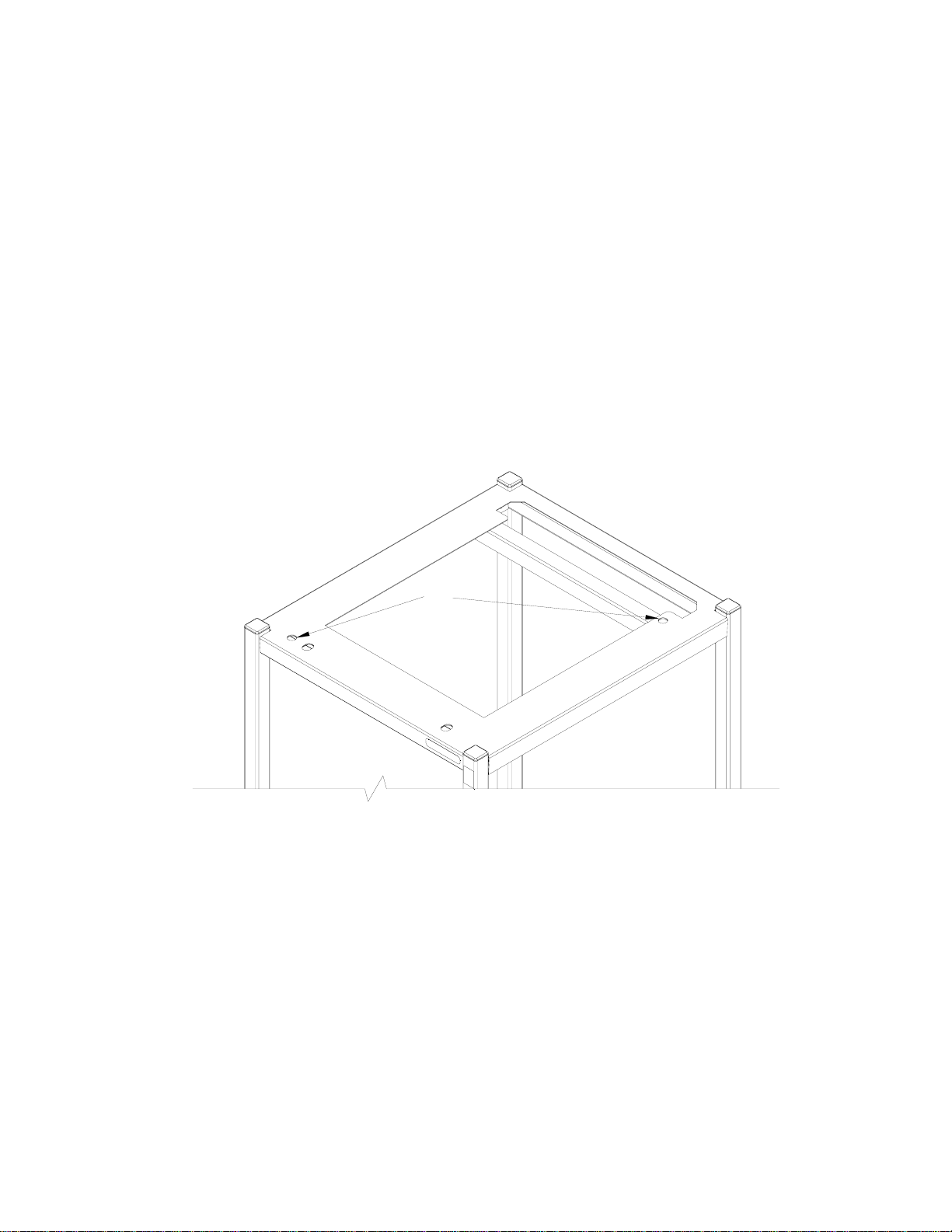
SteamChef Mounting Holes
Figure 1
2 of 7
260BAY Rev. A, 6/07
16. Attach inlet water trains for reservoir and condenser as shown in Figure 3. (Items 12 – 15).
• Each SteamChef steamer is supplied with strainer washers (Figure 3, Item 13) for use on the water
inlets. THESE STRAINER WASHERS MUST BE USED ON THE STEAMER WATER INLET
CONNECTIONS.
17. After RTV sealant has set, replace side panels.
• Do not seal side panels to unit.
• Side panels must be easily removable for service access.
18. Install the flue assembly as shown in Figure 3.
a. Attach the flue adapter (Figure 4, 5, 6, Item 20) to the unit as shown in Figure 4, 5, and 6.
b. Attach the flue riser (Figure 4, 5, 6, Item 21) to the flue adapter as shown in Figure 4, 5, and 6.
c. Attach the flue adapter cover (Figure 4, 5, 6, Item 16) to the flue cover of the bottom steamer as shown
in Figure 4, 5, and 6.
d. Slide the rear flue cover (Figure 4, 5, 6, Item 17) over the flue riser assembly (Figure 4, 5, 6, Item 21).
e. Secure the rear flue cover to the flue riser assembly with two screws on each side.
19. Complete the installation of the steamers as outlined in the SteamChef Installation Manual,
P/N 22CGT-INM and Operator’s Manual, 22CGT-OPM.
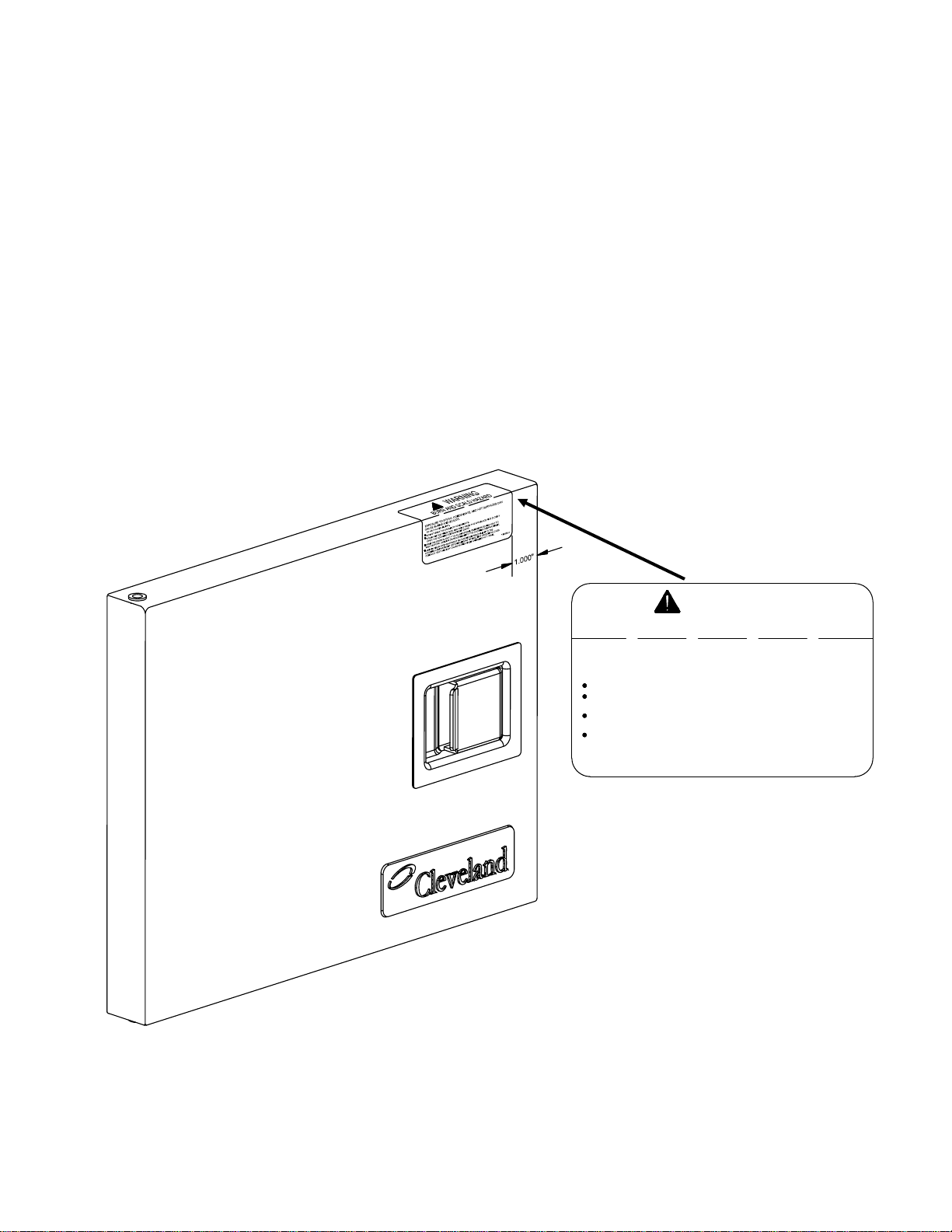
20. Place the Burn and Scald Hazard warning label on the door of the LOWER steamer as shown in Figure 2.
EXPOSURE TO STEAM, CONDENSATE, AND HOT SURFACES CAN
CAUSE BURNS AND SCALD S .
TO HELP AVOID INJURY:
DO NOT BREATHE STEAM OR CONDENSATE.
STAND ON THE HINGE SIDE AND AWAY FROM THE APPLIANCE AND SLOWLY
OPEN THE COOKING COMPARTMENT DOOR.
OPEN THE DOOR SLIGHTLY TO ALLOW STEAM, CONDENSATE AND HEAT TO
VENT BEFORE LOOKING OR REACHING INTO THE COOKING COMPARTMENT.
ALWAYS WEAR DRY HEATPROOF GLOVES WHEN REACHING INTO THE
COOKING COMPARTMENT OR H ANDLING HOT ITEMS. WET OR DAMP GLOVES
CONDUCT HEAT AND MAY CAUSE BURNS WHEN HANDLING HOT ITEMS.
Figure 2
Warning Label Application
WARNING
BURN AND SCALD HAZARD
112523 A
3 of 7
260BAY Rev. A, 6/07
 Loading...