

Cleveland 21-CGA-5 Service Manual

Statement of Responsibilities
This document is for use by experienced and trained Qualified Cleveland Range, LLC Authorized Service
Representatives who are familiar with both the safety procedures, and equipment they service.
Cleveland Range, LLC assumes no liability for any death, injury, equipment damage, or property damage
resulting from use of, improper use of, or failure to use the information contained in this document.
Cleveland Range, LLC has made every effort to provide accurate information in this document, but
cannot guarantee that this document does not contain unintentional errors and omissions.
The information in this document may be subject to technical and technological changes, revisions, or
updates.
Cleveland Range, LLC assumes no liability or responsibility regarding errata, changes, revisions, or
updates.
Qualified Cleveland Range, LLC Authorized Service Representatives are obligated to follow industry
standard safety procedures, including, but not limited to, OSHA regulations, and disconnect / lock out /
tag out procedures for all utilities including steam, and disconnect / lock out / tag out procedures for gas,
electric, and steam powered equipment and / or appliances
All utilities (gas, electric, water and steam) should be turned OFF to the equipment and locked out of
operation according to OSHA approved practices during any servicing of Cleveland Ran ge equipment
Qualified Cleveland Range, LLC Authorized Service Representatives are obligated to maintain up-to-date
knowledge, skills, materials and equipment.
Cleveland Range, LLC
1333 East 179th St., Cleveland, Ohio, U.S.A. 44110
Ph: 1-216-481-4900 Fx: 1-216-481-3782 Visit our Web Site at www.clevelandrange.com

CLEVELAND RANGE 21CGA5
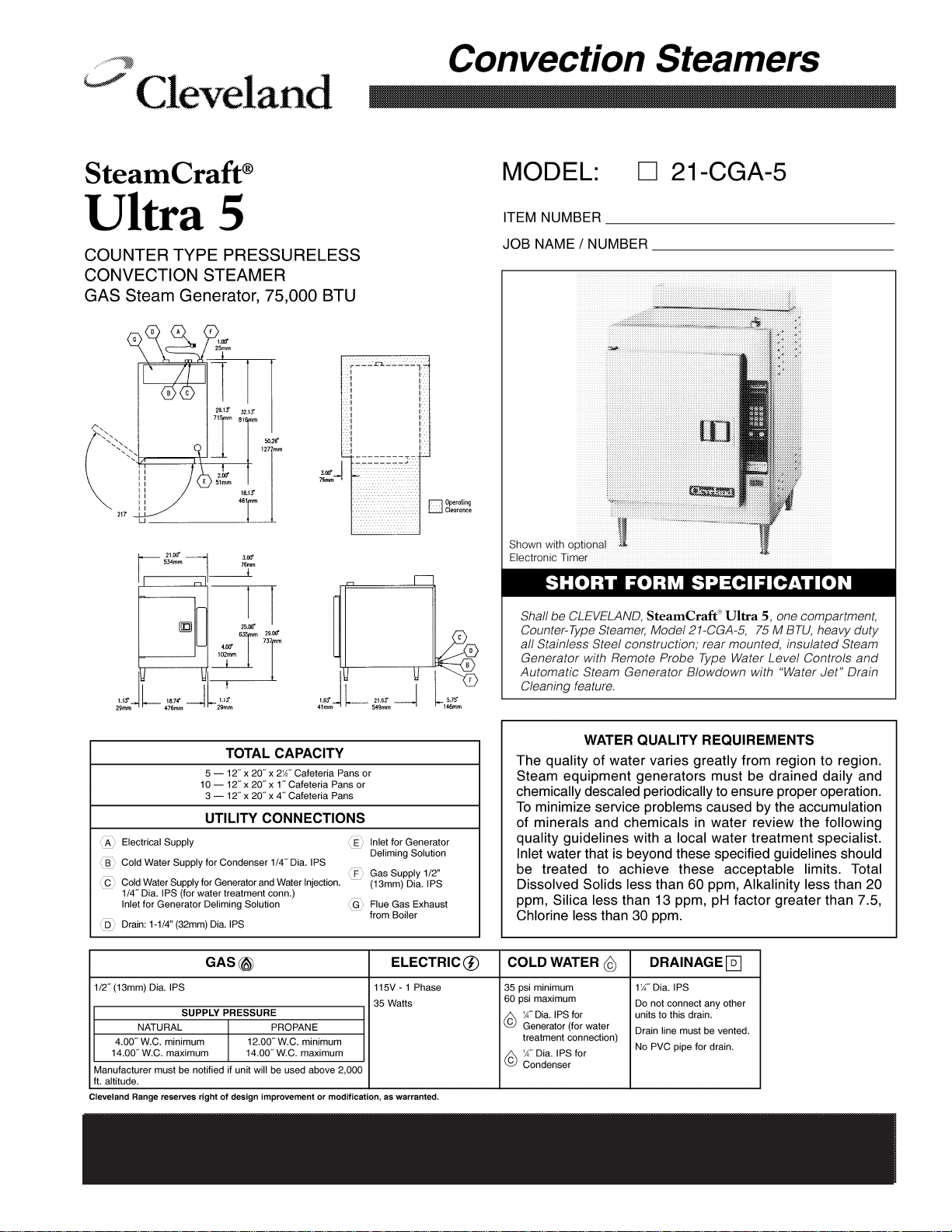
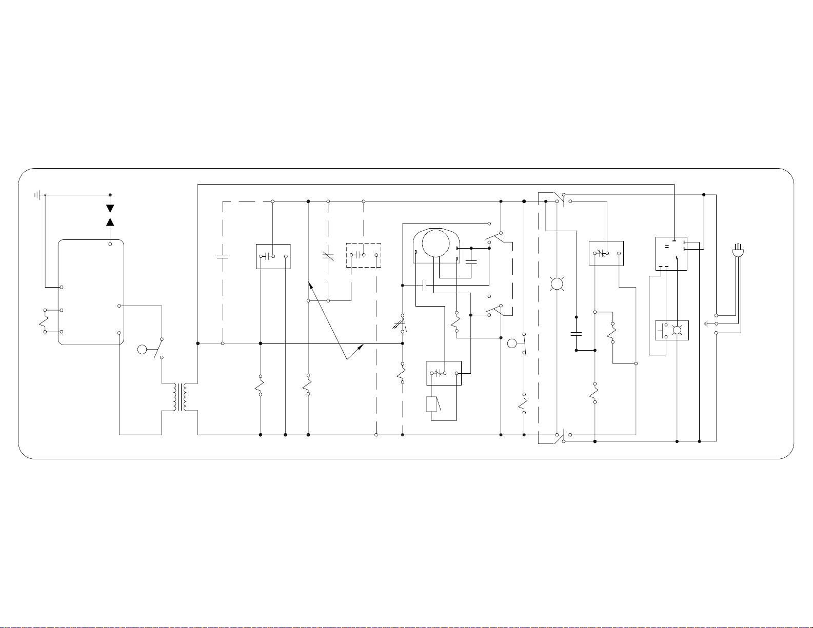
SEQUENCE OF OPERATIONS
STEAMCRAFT ULTRA 5
Mechanical Timer
1. To turn the unit on, depress the red on/off rocker switch.
2. 115 VAC is sent to the red indicator light.
3. 115 VAC is sent to the normally open drain valve closing it.
4. 115 VAC is sent through the normally closed water level (top) float switch to the coil of the
R1 relay
• The R1 relay energizes
• The R1 contacts close 115 VAC is sent to the fill solenoid
5. The fill solenoid opens and the generator fills through the drain valve.
• The water fills to the normally open low water cut off float switch (bottom float).
• The water fills to the normally closed water level (top) float switch.
6. When the timed/manual switch is in the timed position and time is on the timer
• 115 VAC is sent from the timer to the R3 relay coil.
• 115 VAC is sent to the #4 terminal on the clean light timer.
• With the sight glass filled the L.W.C.O. float will be raised and the normally open
• 24 VAC is supplied from the secondary of the transformer through the L.W.C.O. float
• The float is lifted by the water and the switch closes.
• The float is lifted by the water and the switch opens.
• With the switch opened 115 VAC is removed from the coil of the R1 relay.
• The R1 relay deenergizes and 115 VAC is removed from the fill solenoid and
the unit stops filling
• When the water level drops, the operational water float drops closing the switch
and energizing the R1 relay
• The R1 contacts close 115 VAC is sent to the fill solenoid. The unit fills back
to the proper level.
• The R3 relay energizes
• The R3B contacts close sending 115 VAC to the timer motor
• The R3A contacts close sending 115 VAC through the optional door switch to the
condensate valve and the primary of the 24 VAC ignition transformer.
• The clean light timer counts down from the set time (time is set by dip switches on
timer)
• 115 VAC is sent to the amber light in the clean light switch.
• The light is turned off and the clean light timer is reset by depressing the clean light
timer switch.
switch is closed.
switch to the ignition module.

• Spark is sent to the igniter.
• 24 VAC is sent to the gas valve.
• The gas valve opens to the first stage (.7” W.C. natural gas and 2.25” LP)
allowing gas to the burner.
• 6 to 8 seconds later the valve opens to the second stage (3.5” W.C. natural gas
and 10” W.C. LP)
• When the gas is ignited the ignition module detects at least 1.5 micro-amps DC
through the flame and burner ground wire.
• If the 1.5 micro-amps DC is not detected in 4 seconds the ignition module locks
out and has to be reset by removing 24 VAC to the module. This can be done by
turning the steamer on and off.
7. With water in the generator and flame heating it, steam is made and directed into the cooking
chamber.
8. The steamer will continue to steam until the timer runs down.
• When the timer times down 115 VAC is removed from the R3 relay.
• The R3 relay de energizes.
• The R3B contacts open removing 115 VAC from the timer motor
• The R3A contacts open removing 115 VAC from the heat circuit
• 115 VAC is sent to the 3 second timer
• 115 VAC sent to the buzzer for three seconds.
9. The steamer is turned off by depressing the on/off rocker switch.
• 115 VAC is removed from the heat and timer circuits.
• 115 VAC is removed from the drain valve.
• 115 VAC is sent to the 3-minute timer and water is sent in to the now open drain valve
flushing and cooling the drain.
GAS VALVE
L106495 P
IGNITOR
C
IGNITOR
IGNITION MODULE
GND
25V
L.W.C.O.
VALVEVALVE
( GND )
FLOAT
25V
24V
( OPT )
NO
TRANSFORMER
120V
HEAT STANDBY
TIMER
1
R2
VALVE
2
B
CONDENSER
C
C
( OPT )
3
D
DRAIN VALVE
1
R2
WITH INTERMITTENT
2
TIMER (OPT)
REMOVE WIRE A-B & C-D
NC
BLOWDOWN OPTION
ELECTRO-MECHANICAL
TIMER
3
BLOWDOWN
( OPT )
R2
MOTOR
R3A
DOOR
C
NO
R3B
NOC
MANUALTIMEDMANUAL
C
R3
3
1
2
BUZZER
TIMED
OPERATIONAL
WATER FLOAT
3 SEC TIMER
POWER SWITCH
R
R1
NC
NO
(SCS OPT)
SWITCH
A
1
C NO
R1
3 MIN TIMER
3
2
RINSE VALVE
FILL VALVE
NO NO
DESCALE
TIMER
3
4
7
2
8
1
6
5
L
A
L
DESCALE INDICATOR
& RESET SWITCH
BLK
115VAC
WHT
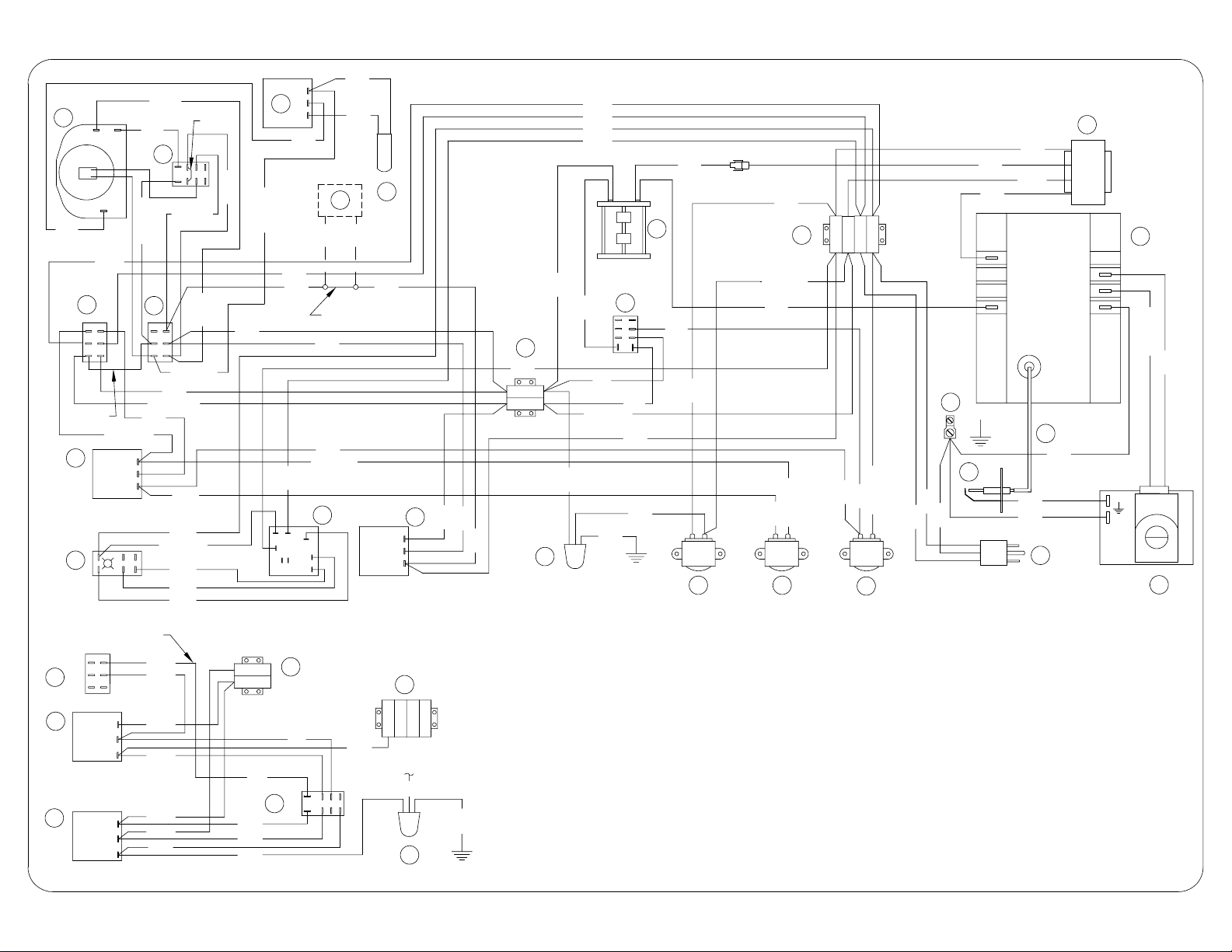
STEAMCRAFT 5.1 GAS, MECHANICAL TIMER
18
NC
PNK
NOC
WHT
ORN
WHT/BLK
1
WHT/BLK
3
WHT/GRA
3
2
1
GRA
4
( THRU SCS, IF INSTALLED )
2
7
20
3
2
1
3
2
1
LT BLU
LT BLU
3
2
17
1
PNK
21
R3
LT BLU
WHT/BLU
BLU
BLK
ORN
LT BLU
BLK
REMOVED W / OPTIONAL
YEL
BLU
WHT/GRA
BLK
2
TAN
WHT/BLK
ORN/BLK
WHT/BLU
BLU
5
WHT
WHT/RED
TAN
TAN
RED
2
3
4
7685
1
INTERMITTENT BLOWDOWN OPTION
ORN
YEL
WHT
BLK
WHT
RED
RED
ORN
WHT
RED
RED
8
N
BLK
21
R2
BLK
BLK
6
RED
DOOR SWITCH ( SCS )
STEAMCRAFT 5.1 GAS w/MECHANICAL TIMER
19
ORN
3
2
1
10
ORN
( TO COND SOL )
RED
11
WHT
BRN
BLK
WHT
BLK
BLK
BRN
9
RED
8
N
RED
BLU
WHT/BLK
25
R1
WHT
ORN
BLU
BRN
10
WHT/BRN
BLK
TB
14
BLK
YEL
WHT
YEL
25V
25V
13
23
VALVE
VALVE
GROUND
LT/BLU
YEL
16
GRN
22
RED
GRN
RED
COND
12
BLU
RINSE
12
WHT/GRA
7
WHT
YEL
ORN
11
BLU
BLU
FILL
12
WHT/BLU
WHT
GRN
BLK
GRN
GRN
15
24
PARTS LIST
24
106400 - GAS VALVE ( NAT )
1064001 - GAS VALVE ( LP )
25
105966 - RELAY
P106495 P
GRN
19993 - POWER SWITCH
1
104224 - TIMED/MANUAL SWITCH
2
20478 - 3 MIN TIMER
3
19994 - DESCALE INDICATOR RESET SW.
4
106911 - DESCALE TIMER
5
108880 - DOOR SW ( SCS ) MAGNETIC
6
106580 - HEAT STANDBY TIMER
7
44168 - TERMINAL BLOCK
8
103726 - FLOAT ASSEMBLY
9
44164 - TERMINAL BLOCK
10
22221 - DRAIN VALVE
11
22218 - WATER SOLENOID S
12
13
20528 - TRANSFORMER 24V
14
20304 - GROUND LUG
15
106461 - LINE CORD
1065681150 - IGNITION CABLE
16
20477 - 3 SEC TIMER
17
110198 - MOTORIZED TIMER
18
41350 - BUZZER
19
106541 - INTMT BLOWDOWN TIMER
20
105966 - RELAY
21
22
300092 - IGNITOR
23
03546 - IGNITION MODULE
 Loading...