

Page 1
Parts Manual
Counter Type Electric Convection Steamer
Series: SteamCraft Models 21CET8
1333 East 179
Cleveland, Ohio 44110
Phone: (216) 481-4900
1-800-338-2204
Fax: (216) 481-3782
www.clevelandrange.com
th
Street
Page 2
Stacking Blower Retro
Kit 110060
Page 3
Page 4
Page 5
Page 6
Page 7
Page 8
Page 9
Page 10
Page 11
Page 12
Page 13
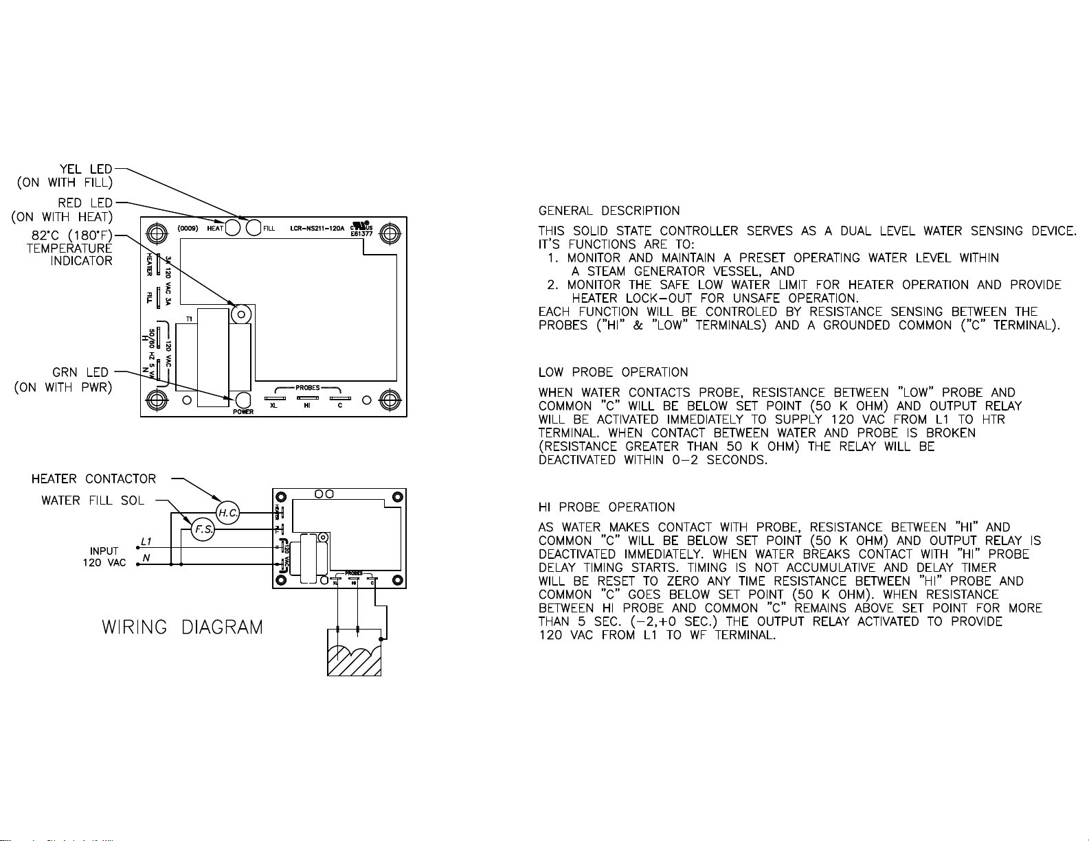
107241 Water Level Board
Page 14
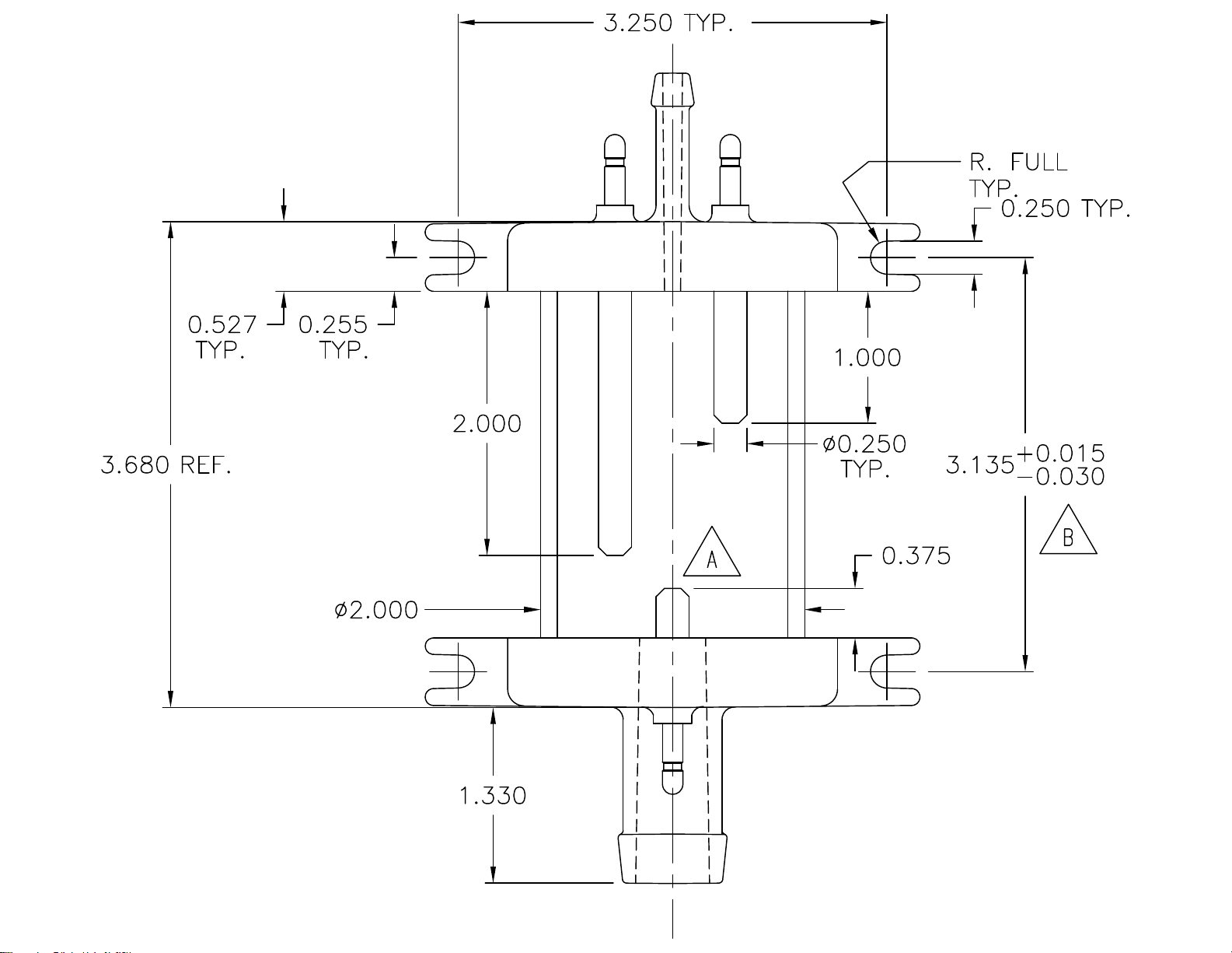
107239 Water Level
Probe Assembly
Page 15
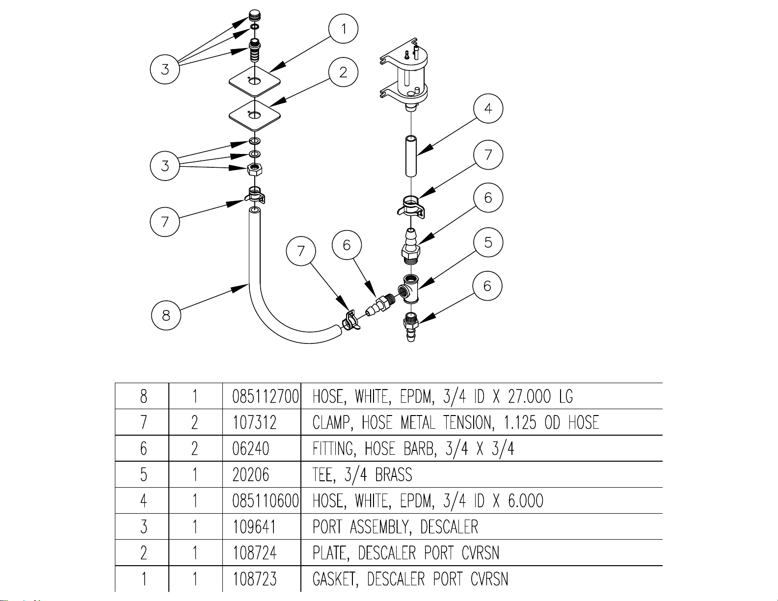
108727
Page 16
Page 17
Page 18

Page 19

Page 20

Page 21

Page 22

Page 23

Page 24

Page 25

Page 26

Page 27

Page 28

Page 29

Page 30

Page 31

CLEVELAND RANGE 21CET8
SEQUENCE OF OPERATIONS
Mechanical Timer
1. Supply power is sent to the primary of the main transformer.
• 115 VAC is sent from the secondary of the main transformer to the on/off rocker,
2. To turn the unit on, depress the red on/off rocker switch.
• 115 VAC is sent to the red power light.
• 115 VAC is sent to normally open drain valve closing it.
• 115 VAC is sent to H and N on the water level board
3. With the water level board energized and no water in the generator
• 5 seconds later 115 VAC is sent from the FILL terminal to the fill solenoid.
• The fill solenoid opens and the generator fills through the drain valve.
• The water fills to the low probe shorting it to ground
• 115 VAC is sent to the heat standby timer which will energize 3 seconds every 4
minutes to maintain heat while unit is idle
• 115 VAC is sent from the HEAT terminal to the timed manual switch.
4. When the timed/manual switch is in the timed position and time is on the timer
• 115 VAC is sent from the timer to the R2 relay coil
• R2 relay energizes closing the R2A and R2B contacts
• 115VAC is sent through the now closed R2B contacts to the timer motor
• 115 VAC is sent through the now closed R2A contacts through the door switch to the
normally closed contacts of the high limit switch.
• 115 VAC is then sent through the high limit to the coil of condensate solenoid
• The condensate solenoid opens spraying cold water down the compartment drain.
• 115 VAC is also sent through the high limit to the coil of the contactor.
• 115 VAC is sent to the clean light timer.
• When the clean light timer times down 115 VAC is sent to the clean light switch.
• When the clean light switch is depressed the clean light timer is reset.
5. When the contactor coil is energized supply voltage is sent to both of the elements.
• The elements are energized and the water is heated to steam.
• Steam is directed to the cooking compartment.
6. When the timer times out
• 115 VAC is sent to the 3 second timer and then to the buzzer for 3 seconds.
• 115 VAC is removed from the R2 relay.
• R2A contacts open de energizing the heat circuit
• R22B relay contacts open removing the 115 VAC from the timer motor
Page 32

7. When the water level reaches the high probe then 115 VAC is removed from the FILL
terminal and the fill solenoid is turned off.
8. After the water level drops below the high probe for 5 seconds 115 VAC is sent to the FILL
terminal again.
9. The red on/off switch is depressed and the unit is turned off.
• 115 VAC is removed from the heat and timer circuit.
• 115 VAC is removed from the normally open drain valve allowing the steamer to drain.
• 115 VAC is sent to the 3-minute timer and the fill solenoid is energized for 3 minutes
flushing the drain.
Page 33

STEAMCRAFT 3.1 MECHANICAL TIMER (PROBE)
CUSTOMER
CONNECTION
380/415V
3Ø
W/ NEUTRAL
L1
L2
L3
N
TB
FU
FU
FIELD CONVERSION FROM 3Ø
TO 1Ø IS NOT PERMITTED
DRYING ELEMENT
HEATING ELEMENTS
CUSTOMER
CONNECTION
1Ø
CUSTOMER
CONNECTION
3Ø
BLK
DESCALE
TIMER
L1
L2
L3
RESET CIRCUIT
BREAKER
POWER
SWITCH
L1
L2
3Ø
TB
4
1Ø
TB
23
1
6
87
5
3
1
3 MIN TIMER
2
CONTACTOR
FU
FU
CONTACTOR
FU
FU
L
NO
POWER ON
R
H4
X1
A
FILL VALVE
120V
L
NO
DRYING ELEMENT
HEATING ELEMENTS
H1 PRIMARY
X2 SECONDARY
DESCALE INDICATOR
& RESET SWITCH
WHT
MANUAL
MOTOR
ELECTRO-MECHANICAL
BLOWDOWN OPTION
TIMED TIMEDMANUAL
R2B
C NO
C
NO
C
R2A
NC
NO
TIMER
1
3
HEAT STANDBY
TIMER
R1
C NC
INTERMITTENT
BLOWDOWN
1
2
3
SWITCH
(SCS OPT)
R1
NO C
2
TIMER
HEAT
FILL
H
N
R2
DOOR
( STACKED UNITS OPTION )
WATER
BOARD
XL
C
HI
3 SEC TIMER
3
2
1
R1
( OPT )
HI LIMIT
SWITCH
COOLING FAN
DRAIN VALVE
TO
PROBES
BUZZER
CONTACTOR
CONDENSER
VALVE
L106347 M
Page 34

BLK
3
20
2
1 BLK
LT BLU
19
PNK
WHT/BLK
3
4
NC
WHT
1
NOC
WHT/GRA
3
2
1
ORN
WHT/BLK
GRA
23
R2
ORN/BLK
BLK
2
WHT/RED
WHT
TAN
TAN
RED
BLU
LT BLU
18
WHT/BLU
LT BLU
SINGLE PHASE WIRING CONFIGURATION
TO
FUSE BLOCK
L1 L2 L3
TERMINAL BLOCK
CUSTOMER
CONNECTION
WHT/BLK
WHT/BRN
17
BLU
BLK
REMOVED W / OPT
DOOR SWITCH ( SCS )
YEL
YEL
TAN
WHT/BLK
WHT
BLK
5
3
2
1
4
6
7
58
BRN
21
BRN
BLK
DRYING ELEMENT
BLK
HEATER
RED
ELEMENT
WHT
DRYING ELEMENT
BLK
HEATER
RED
ELEMENT
WHT
STEAMCRAFT 3.1 MECHANICAL TIMER (PROBE)
WHT
BLK
WHT
BLK
BLK
RED
GRN
16
RED
BLK
15
HEAT FILL
YEL
C
HI
XL
NH
TAN
RED
WHT
JUMPER POSITION
FOR 480 V
OPERATION
H2
H4 H3 H1
WHT/BLU
26
BLK
YEL
TIMED/MANUAL SWITCH
6
22
7
N
6
3
WHT
2
1
INTERMITTENT BL OWDOWN OPTION
3
WHT
2
YEL
BLK1
WHT
3
RED
2
RED
1 RED
TAN
RED
9
N
( TO HIGH LIMIT )
BLK
WHT
RED
BLU
WHT/BLK
8
7
23
RED
GRN
COND
BLK
BRN
TIMED/MANUAL SWITCH
( THRU SCS )
BLK
( TO COND SOL )
BRN
RED
BLU
RED
WHT/BRN
10
GRN
8
WHT/BLU
FILL
19993 - POWER SWITCH
1
104224 - TIMED / MANUAL SW
2
20478 - 3 MIN TIMER
3
4
19994 - DESCALE IND RESET SWITCH
106911 - DESCALE TIMER
5
109239 - HEAT STANDBY TIMER
6
44168 - TERMINAL BLOC K
7
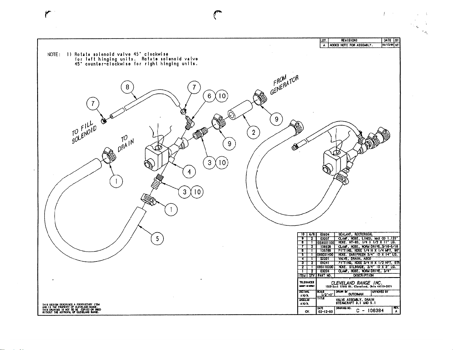
22221 - DRAIN VALVE
8
107211 - COOLING FAN ( OPT )
9
22218 - WATER SOLENOI DS
10
11
103731 - HI LIMIT SWITCH
300022 - CONTACTOR
12
108331 - RESET CIRCUIT BRKR
13
20535 - TRANSFORM ER
14
15
107241 - WATER BOARD
107239 - PROBE
16
WHT
WHT
BLK
14
H4 H2
208/240
VOLT
BLK
X2X1
H1
H3
BLK
24
L2
L1
L3
CUSTOMER CONNECTION
WHT/BRN
BRN
BLK
11
BLK
PARTS LIST:
BLK
BLK
BLK
BLK
FU
FU
27
28
13
BLK
WHT
WHT
WHT
25
12
BRN
17
18
19
20
21
22
23
24
25
26
27
28
BLK
HEATER
ELEMENT
RED
DRYING ELEMENT
BLK
WHT
HEATER
ELEMENT
RED
WHT
DRYING ELEMENT
108880 - DOOR SW ( MAGNETIC )
41350 - BUZZER
110198 - MOTORIZED TIMER
20477 - 3 SEC TIMER
104234 - CONTACTOR
106541 - INTMT BLOWDOWN TIMER
105966 - RELAY
101540 - END SEGMENT
101541 - TERM BLOCK SECTIONAL
20304 - GROUND LUG
109380- 3.5 AMP, 600V FUSE
109374 - FUSE BLOCK
P106347 M
Page 35

Page 36

Page 37

STEAMCRAFT 3.1 ELECTRONIC TIMER (PROBE)
CUSTOMER
CONNECTION
380/415V
3Ø
W/ NEUTRAL
L1
L2
L3
N
TB
FU
FIELD CONVERSION FROM 3•
TO 1• IS NOT PERMITTED
DRYING ELEMENT
HEATING ELEMENTS
CONNECTION
CUSTOMER
CONNECTION
3•
BLK
DESCALE
POWER SWITCH
CUSTOMER
1•
RESET CIRCUIT
TIMER
L1
L2
L3
BREAKER
TB
3
4
7
L1
L2
2
1
8
3 MIN TIMER
CONTACTOR
TB
FU
FU FU
DRYING ELEMENT
CONTACTOR
FU
FU
H4
X1
120V
L
6
5
NO
L
A
NO
HEATING ELEMENTS
H1 PRIMARY
X2 SECONDARY
DESCALE INDICATOR
& RESET SWITCH
WHT
3
2
1
POWER ON
FILL VALVE
R
COMPARTMENT
THERMAL SWITCH
TIMED
MANUAL
HEAT STANDBY
TIMER
BLOWDOWN OPTION
( SCS OPT )
R1
C
1
FU
DOOR
SWITCH
MAGNETIC
3
NC
TRANSFORMER
ELECTRONIC
1
2
INTERMITTENT
BLOWDOWN
TIMER
24 VAC
TIMER
R1
CNO
WATER
HEAT
BOARD
FILL
H
N
HIXL C
COIL R1
( OPT )
HI LIMIT
SWITCH
( STACKED UNITS OPTION )
COOLING FAN
DRAIN VALVE
PROBES
CONTACTOR
CONDENSER
VALVE
TO
2
3
L106346 M
Page 38

Page 39

PROBLEM:
21CET8
21CET16
21CEA10
Steamer won't
steam.
Steamer won't
steam
Is the red light
on?
Yes
No
Is there supply
voltage to the
primary of the
transformer?
Yes
Supply power to
No
the s t eam er.
Replac e the
water boar d
Replace the wire
from the water
board to the long
probe.
See
STEAMER
WON'T FIL L
Replace the wires
to the water
board.
jumper between XL and
No
C on the water b oard , i s
there 120 VA C between
N and Heat?
No
there d ebr i s on
With a
Yes
Is
the Long
probe?
No
No
Is there water
in the sight
Is there 120 VAC
between t erm i n als H
and N on the wat er
Is there 120 VAC
between ter m i nals
No
N and Heat on t he
water board ?
115 V AC t o th e
common term i n al of
the timed/manual
glass?
Yes
board?
Yes
Yes
Is there
switch?
Replace the wires
No
to the switch.
Is there 115 VAC at
the secondary of
the transformer?
Yes
Replace the on/ of f
rocker switch
No
Replac e the
transformer.
Yes
Clean or r ep lace
the probe ass y.
Yes
Does
the unit st eam
in Manual
mode?
Yes
Replac e the
timer.
Does t he
No
st eam er have
the opt i onal
door switch?
steamer steam w i th
door swit c h
bypass ed?
Adjust or replac e
the door switch.
Yes
Does
Yes
Is there
115 V AC t o th e
No
No
high limit?
Is there 115
VAC l eaving
the high limit?
Is there 115
VAC to the coil
of the
contactor?
Is th ere an
amp draw at
the elem en t ?
Wait longer for t h e
steam. Heat fr om t h e
element will heat the
water to steam.
Yes
Yes
Yes
Yes
No
No
No
No
Replac e the
wires to the
high limit.
Replac e the
high limit.
Replac e the
wires to the
contactor coil.
Replac e the
element.
Page 40

PROBLEM:
21CET8
21CET16
24CEA10
Steamer wont
fill
Steamer wont fill.
Yes
Is there supply
voltage to the
steamer?
Yes
No
Supply power to
the s t eam er.
Replace wiri n g t o
the fill solenoid.
Is there water
to the
steamer?
Is there 120 VAC
between th e H and N
on the water b oard?
Is there
120 VAC
between Fill and
N on the water
board?
Is there
No
120 VAC across
the coil of t h e fill
solenoid?
Yes
Yes
Yes
Yes
Supply cold water
No
Replace the on/ of f
No
No
to the s t eamer.
rocker switch.
Remove
the wire f r om t h e H I
terminal on the water
board. Is there 120 VAC
between F i l l
and N?
Yes
Is there
debr i s on th e
HI probe in the
probe as sy?
No
Replace the water
No
Replace the wire
to the Hi p r ob e.
board
Replace wiri n g t o
drain valve.
Replace t h e wi r i ng
to the intermittent
blowdown timer.
No
No
Replace t h e fill
solenoid
Does
the s t eam er have
the opt i onal
intermittent
blowdown timer?
Yes
Is
there 120 VAC
between ter m i nals
2&3 on the timer?
Yes
Replac e the
intermittent
blowdown timer.
No
No
Is
water leaving
the fill
solenoid?
Yes
Is there
120 VAC across
the coil of the
drain valve?
Yes
Is water
draining from
the generator?
Yes
Replace the drain
valve.
If water i s leaving
No
and not draining
from the generator
where is it g oi ng ?
check for leaks..
Yes
Clean t h e probes
or replace the
probe as sy.
the fill solenoid
Page 41

PROBLEM:
21CET8, 21CET16, 24CEA10
Electronic timer displays "PAUS" and won't count down
Timer displays "paus"
and won't count down
Is steam heati ng
Replac e the
thermo-switch
cabinet above 192
degrees (the set
thermo-switch)?
Does the timer
count down when
Yes
the thermo-switch
is bypassed?
the cook i n g
No
temp of the
Yes
No
See
Steamer
won't steam
Replac e the
electronic ti m er
Steam leaks
around the
door
Is COLD water
supplied to both
water li n es t o t h e
steamer?
Yes
Is the door gasket
phys ic ally
damaged?
Yes
Turn over the
gasket or
replace it.
water(35-60 p si) t o
No
Is the door ou t of
No
Supply cold
the s t eam er.
alignment ?
Yes
Replac e the
door bearings
and pins.
PROBLEM:
21CET8, 21CET16, 24CEA10
Steam leaks around the door.
Is there 120 VAC
No
Is the drain
obstructed?
Yes
Remove the
obstruction
across the coil of
No
the condensate
solenoid?
Is the solenoid
Yes
opening?
No
No
Replac e the
wiring to the
condensate
solenoid.
Replac e the
condensate
solenoid.
Yes
Replac e the
condensate spray
nozzle
Page 42

PROBLEM:
21CET8
21CET16
24CEA10
Steamer overfills.
(Water sprays into cooking
cabinet)
Steamer overfills
(Water sprays into the
cooking cabinet)
Start
There is an
obstruction in th e
drain. Remove the
obstruction.
Yes
Does
the rise in t he wat er
level in the sig h t gl as s
stop when the cooking
cabinet door is
opened?
No
There is an
obstruction in th e
generator caus i ng
it to pressurize.
Delim e the steam
generator
thor oughly.
Replace the three
minute timer.
Yes
Yes
Does
the water rise in t h e
sight glass when steam
is generat ed and 0 V A C
to the fill solenoid?
No
Replace t h e fill
solenoid
There is an obstruction in
the plumb in g t o and from
the sight glass . Remove
the debris (delime
thoroughly).
Remove the
wire from the Fill
terminal on the water
board. Is there 120 VAC
across the coil of th e
fill
solenoid?
Yes
Yes
Yes
Does
the water l evel in th e
sight glas s st op at t h e
HI (short) probe on the
initial fill?
No
Does
water s p r ay in t h e
cabinet before t he
water reach es the H I
(short) probe?
No
Is
there 120 VAC
across the coil of ;t h e
fill solenoid when the
HI (short) probe is
submerged?
Replace the water
level boar d.
Clean or r ep lace
the pr obe
assembly.
Yes
water boar d ju m p ed,
between t erm i n als N
Yes
No
With HI and C
terminals on the
Is there 120 VAC
and Fill?
No
Is
there d ebr i s on
the HI (short)
probe?
No
Replace the wire
to the probe
assembly
No
Replace t h e fill
solenoid
Page 43

Steamer won't
stop steaming
Is the
timed/manual switch
in the timed posit i on
with no time on the
timer?
Yes
Steamer will steam
constantly in th e
manual p os i t i on. P u t
No
the timed/manual
switch in the timed
position with no tim e on
PROBLEM:
21CET8
21CET16
24CEA10
Steamer won't stop steaming with
door open
the timer.
Does th e st eam er
have the op t ional
door switch?
Yes
Adjust or replac e
the door s wi t ch .
No
Does steam er
continue to steam with
both wires removed
from terminal 1 on t h e
heat st andby
timer?
No
Replac e the h eat
standby timer.
21CET8, 24CEA10
Steamer won't preheat
Yes
Replace the timer.
Problem:
Steamer
won't
preheat
Is there
120 V AC t o th e
coil of the
contacter?
Yes
No
Is
there an am p
draw at t h e
element?
Yes
Replac e the
contactor
voltag e i s r em oved
from t he elem en t
steam is sti l l mad e
No
for approxi m ately
10 seconds . This
When supply
is normal.
Is the
timed/manual
switch in t h e ti m ed p os t i on
with tim e on it or i n t h e
manual
postion?
Yes
See Problem:
steamer won't
steam.
This steamer is
not equiped with a
thermostat. The
No
switch must be in
manual or time
must be on the
preheat
timed manual
timer.
Page 44

Problem:
21CET16
Steamer won't preheat
Steamer won't
preheat
Does th e st eam er
have a pr eheat
thermostat
Yes
Is there
continuity on the
normally closed
contacts of t h e
preheat
thermostat?
No
No
Yes
Is the
timed/manual
switch in t h e ti m ed p os t i on
with tim e on it or i n t h e
manual
postion?
Yes
See Problem:
steamer won't
steam.
This steamer is
not equiped with a
thermostat. The
No
timed manual
switch must be in
manual or time
must be on the
preheat
timer.
Replace t he pr eh eat
thermostat
Page 45

STEAMCRAFT 3.1 MECHANICAL TIMER ( FLOAT )
CUSTOMER
CONNECTION
380/415V
3Ø
W/ NEUTRAL
L1
L2
L3
N
TB
FU
FU
FIELD CONVERSION FROM 3
TO 1Ø IS NOT PERMITTED
DRYING ELEMENT
HEATING ELEMENTS
CUSTOMER
CONNECTION
1Ø
CUSTOMER
CONNECTION
3Ø
BLK
DESCALE
TIMER
POWER
SWITCH
L1
L2
3Ø
L1
L2
L3
TB
RESET CIRCUIT
BREAKER
32
4
78
3 MIN TIMER
1Ø
TB
CONTACTOR
FU
FU
DRYING ELEMENT
CONTACTOR
FU
FU
H4
X1
120V
L
1
6
5
3
NO NO
2
L
A
HEATING ELEMENTS
H1 PRIMARY
X2 SECONDARY
DESCALE INDICATOR
& RESET SWITCH
FILL VALVE
WHT
1
R1
POWER ON
NO C
R
R3B
NOC
C
NO
MOTOR
R3A
NC
ELECTRO-MECHANICAL
TIMER
R2
1
2
3
HEAT STANDBY
TIMER
BLOWDOWN OPTION
R2
NCC
1
2
3
MANUALTIMED
C
NO
CNO
LOW WATER
INTERMITTENT
BLOWDOWN
TIMER
TIMED
R3
DOOR
SWITCH
(SCS OPT)
CUT-OFF
R1
WATER LEVEL
3 SEC TIMER
3
BUZZER
2
1
COIL R2
( OPT )
CONTACTOR
CONDENSER
HI LIMIT
SWITCH
VALVE
( STACKED UNITS OPTION )
COOLING FAN
DRAIN VALVE
L300163 D
Page 46

3
20
2
1
19
LT BLU
ORN
NOC
23
BLK
BLK
LT BLU
18
R3
WHT/BLU
LT BLU
YEL
TAN
BLU
TAN
TAN
RED
PNK
WHT/BLK
WHT/GRA
3
4
NC
WHT
1
2
1
ORN/BLK
WHT/BLK
2
WHT/BLK
GRA
WHT/GRA3
BLU
WHT
WHT/RED
SINGLE PHASE WIRING CONFIGURATION
TO
FUSE BLOCK
21
L2L1 L3
TERMINAL BLOCK
CUSTOMER
CONNECTION
WHT/BLK
WHT/BRN
17
BLU
RED
BLK
BRN
5
1
6
587
BLK
BLK
HEATER
ELEMENT
HEATER
ELEMENT
BLK
REMOVED W / OPT
DOOR SWITCH ( SCS )
BLK
YEL
WHT
23
4
BRN
DRYING ELEMENT
BLK
RED
WHT
DRYING ELEMENT
BLK
RED
WHT
STEAMCRAFT 3.1 MECHANICAL TIMER ( FLOAT )
WHT
BLK
WHT
BLK
15
RED
RED
BLK
RED
WHT
BLU
BRN
BLK
BLU
WHT/BLK
BRN
WHT/BRN
COND
RINSE
BLK
23
WHT/GRA
BLU
R1
7
N
BLU
WHT
BLK
YEL
6
3
2
1
RED
GRN
8
9
BLK
INTERMITTENT BLOWDOWN OPTION
7
N
6
22
WHT
3
2
YEL
BLK1
WHT
RED
2
RED
1
( TO HIGH LIMIT )
BLK
R2
23
WHT3
RED
RED
TO TIMED/MANUAL
BLK
SWITCH
( THRU SCS )
( TO COND SOL )
RED
8
GRN
WHT/BLU
26
BLU
BLU
BLU
WHT/GRA
10
FILL
1
19993 - POWER SWITCH
2
104224 - TIMED / MANUAL SW
20478 - 3 MIN TIMER
3
4
19994 - DESCALE IND RESET SWITCH
106911 - DESCALE TIMER
5
109239 - HEAT STANDBY TIMER
6
44168 - TERMINAL BLOCK
7
22221 - DRAIN VALVE
8
107211 - COOLING FAN ( OPT )
9
22218 - WATER SOLENOIDS
10
103731 - HI LIMIT SWITCH
11
300022 - CONTACTOR
12
108331 - RESET CIRCUIT BRKR
13
14
20535 - TRANSFORMER
15
103726 - FLOAT
16
--
WHT
WHT
BLK
14
X1
X2
208/240
VOLT
H3
H2H4
H1
BLK
BLK
24
L2L1
L3
CUSTOMER CONNECTION
WHT/BRN
BRN
WHT/BLU
BLK
11
BLK
PARTS LIST:
BLK
BRN
BLK
25
WHT
WHT
WHT
BLK
BLK
BLK
FU
FU
2827
JUMPER POSITION
FOR 480 V
OPERATION
H3
H2H4
12
BLK
HEATER
ELEMENT
RED
DRYING ELEMENT
BLK
WHT
HEATER
ELEMENT
RED
WHT
DRYING ELEMENT
17
108880 - DOOR SW ( MAGNETIC )
41350 - BUZZER
18
110198 - MOTORIZED TIMER
19
20477 - 3 SEC TIMER
20
21
104234 - CONTACTOR
22
106541 - INTMT BLOWDOWN TIMER
105966 - RELAY
23
101540 - END SEGMENT
24
101541 - TERM BLOCK SECTIONAL
25
20304 - GROUND LUG
26
109374 - FUSE BLOCK
27
109380 - FUSE 3.5A 600V
28
P300163 D
H1
Page 47

Page 48

Page 49

Page 50

Page 51

Page 52

Page 53

Page 54

Page 55

Descaling Procedure-SteamCraft Ultra and Gemini Series
How Much DISSOLVE to Use
Model Dissolve
Ultra 3 1/2 Gallon
Ultra 5 1 Gallon
Ultra 10 (Elec.) 1 Gallon (ea.)
Ultra 10 (Gas) 1½ Gallon
Gemini 6 & 10 1 Gallon (ea.)
1. Turn the unit OFF and open the
doors:
This will drain and rinse the generator for about
3 minutes.
2. Turn the unit power back On:
The generator will begin to refill with water.
3. Select Timed with the Timed/Manual
switch:
DO NOT start the timer, since you do not want
to heat the water during descaling. Leave the
doors open.
6. Let the descaler soak in generator for
approximately one hour:
7. After one hour, turn the unit power
Off:
This will drain and rinse the generator
for about 3 minutes.
Remove descaling port cap and add
4.
with the specified amount of
DISSLOVE:
Do this while the unit is refilling. The generators
can take-up to 8 minutes to refill.
After refill has stopped, add extra tap
5.
(See chart above)
water into the descaling port until
liquid is seen entering the cooking
cabinet.
coming out of the drain,
Adding extra water when descaling will raise the
descaling solution higher than the normal fill level,
allowing the DISSOLVE to work on sensors and
surfaces above the water line
Note: Some SteamCraft Ultra models (the
electric powered Ultra 10 and Gemini 6 and 10,
for example) have two generators and two
descaling ports. Both units should be descaled
at the same time, using this procedure
Note: Ultra 10 gas will have liquid
8. After the 3-minute drain cycle
completes, turn the unit back ON. After
the filling has stopped, add water until
liquid enters the cooking compartment (or
drain for the ultra 10 gas), and then turn
the unit OFF. This will drain and flush any
residue from the water level control
assembly. Replace descaling cap.
After the 3 minute drain cycle
9.
completes, Turn the unit ON and set
the Timer for 20 minutes:
Time/Manual switch is in the timed setting
and the doors are closed.
Make sure the
10. When the timer times out (after 20
minutes) turn the power Off:
This will drain and rinse the generator for
about 3 minutes.
This ends the descaling procedure. You can
now turn the unit back on and resume normal
startup and cooking operations.
Page 56

 Loading...