

Page 1

Statement of Responsibilities
This document is for use by experienced and trained Qualified Cleveland Range, LLC Authorized Service
Representatives who are familiar with both the safety procedures, and equipment they service.
Cleveland Range, LLC assumes no liability for any death, injury, equipment damage, or property damage
resulting from use of, improper use of, or failure to use the information contained in this document.
Cleveland Range, LLC has made every effort to provide accurate information in this document, but
cannot guarantee that this document does not contain unintentional errors and omissions.
The information in this document may be subject to technical and technological changes, revisions, or
updates.
Cleveland Range, LLC assumes no liability or responsibility regarding errata, changes, revisions, or
updates.
Qualified Cleveland Range, LLC Authorized Service Representatives are obligated to follow industry
standard safety procedures, including, but not limited to, OSHA regulations, and disconnect / lock out /
tag out procedures for all utilities including steam, and disconnect / lock out / tag out procedures for gas,
electric, and steam powered equipment and / or appliances
All utilities (gas, electric, water and steam) should be turned OFF to the equipment and locked out of
operation according to OSHA approved practices during any servicing of Cleveland Ran ge equipment
Qualified Cleveland Range, LLC Authorized Service Representatives are obligated to maintain up-to-date
knowledge, skills, materials and equipment.
Page 2
Cleveland Range, LLC
1333 East 179th St., Cleveland, Ohio, U.S.A. 44110
Ph: 1-216-481-4900 Fx: 1-216-481-3782 Visit our Web Site at www.clevelandrange.com
Page 3

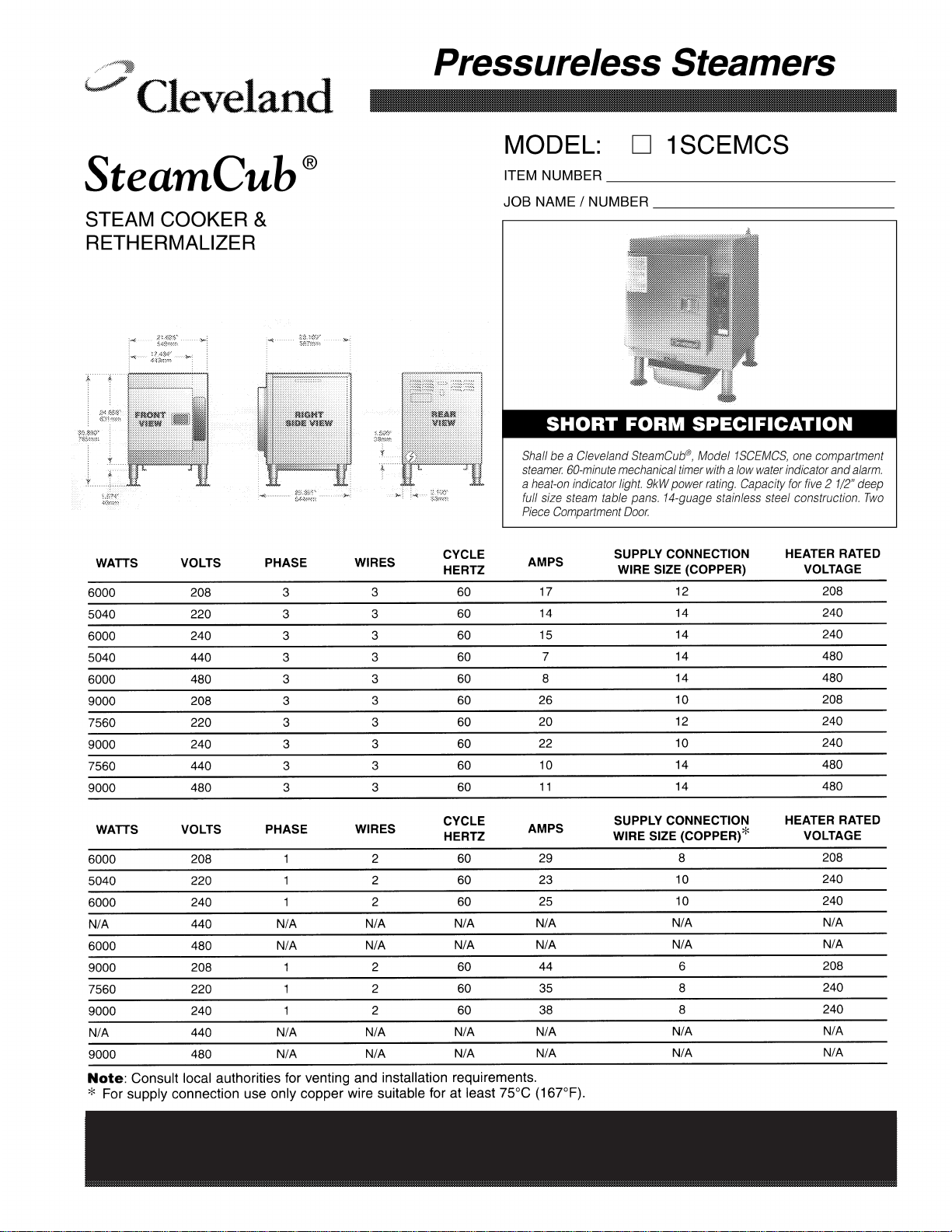
CLEVELAND RANGE 1SCE
104026 DOOR GASKET
FK108879 DOOR MAGNET
108880 MAGNETIC DOOR SWITCH
S108252 DRAIN VALVE
SEQUENCE OF OPERATIONS
STEAM CUB
Mechanical Timer
When using these instructions refer to the STEAM CUB wiring schematic.
1. Supply Voltage is sent to the primary of the power transformer.
• 115 VAC is sent from the secondary of the power transformer to the on/off
switch.
2. To turn the unit on, place the 115 VAC switch in the on position.
• 115 VAC is sent to the H terminal of the water board.
• 115 VAC is sent to the normally open contacts (R2B) of the R2 relay.
• 115 VAC is sent to the normally open contacts (R1A) of the R1 relay.
• 115 VAC is sent to the normally open contacts (R3B) of the R3 relay.
3. After water has been placed in the cooking cavity and the probe is grounded the water
board will have 120 VAC at the heat terminal.
• 115 VAC is sent through the normally closed contacts (R3A) of the R3 relay and
the normally closed contacts (R2A) to the door switch.
• If the water level drops below the probe the water board will remove 115 VAC
from the HEAT terminal and send it to the FILL terminal.
• From the FILL terminal 115 VAC is sent to the coil of the R3 relay.
• The R3 relay energizes and the normally closed contacts (R3A) open.
• The normally open contacts (R3B) will close and 115 VAC is sent to the
ADD WATER light and buzzer.
4. With the door closed the door switch is closed and 115 VAC is sent to the
timed/manual switch.
5. In the timed mode and time on the timer, or in the manual mode, 115 VAC is sent
through the thermostat to the coil of the contactor.
• The contactor closes and supply voltage is sent to the elements and the water is
heated to steam.
• When the cabinet reaches 205 degrees the thermostat opens and 115 VAC is
removed from the coil of the contactor and the elements are de-energized.
• When the unit cools the thermostat closes and the steamer heats again.
6. If one of the high limits (located on the heater blocks) opens a potential difference is
placed across the coil of the R1 relay.
• The R1 contacts will close energizing the R2 relay coil.
• The normally open R2B contacts will close latching in the R2 coil.
• The normally closed R2A contacts will open de-energizing the heater contactor.
• The normally open R2A contacts will close energizing the buzzer.
• The buzzer will sound until the unit is turned off.
7. To turn the unit of the rocker switch is depressed and the 115 VAC is removed from
the heat circuit.
Page 4

Page 5

Cleveland Range, LLC
1333 East 179th St., Cleveland, Ohio, U.S.A. 44110
Ph: 1-216-481-4900 Fx: 1-216-481-3782 Visit our Web Site at www.clevelandrange.com
Page 6

CLEVELAND RANGE 1SCE
SEQUENCE OF OPERATIONS
STEAM CUB
Electronic Timer
When using these instructions refer to the STEAM CUB wiring schematic.
1. To turn the unit on, place the 115 VAC switch in the on position.
• 115 VAC is sent to the H terminal of the water board.
• 115 VAC is sent through the normally closed contacts (R2A) of the R2 relay to
the primary of the 24 VAC transformer.
• From the secondary of the 24VAC transformer 24 volts is sent to the
programmable timer.
2. After water has been placed in the cooking cavity and the probe is grounded the water
board will send 115 VAC to the door switch and the coil of R3 closing the normally
open contacts to the programmable timer.
• This tells the timer there is water allowing it to time down.
• If the water level drops below the probe the water board will stop sending 115
VAC to the coil of R3. This will open the R3 contacts and the timer will
display “add h2o”.
• Without the minimum water level the water board will also prevent 115 VAC
from getting to the door switch.
3. With the door closed the door switch is closed and 115 VAC is sent to the normally
open contacts of the programmable timer.
• When the programmable timer is calling for heat (the heat indicator light is
energized) 115 VAC is sent to the coil of the heater contactor closing the
contacts and energizing the elements.
4. If one of the high limits (located on the heater blocks) open a potential difference is
placed across the coil of the R1 relay.
• The R1 contacts will close energizing the R2 relay coil.
• The normally open R2B contacts will close latching in the R2 coil.
• The normally closed R2A contacts will open de-energizing the 24 VAC
transformer.
• The normally open R2A contacts will close energizing the buzzer.
• The buzzer will sound until the unit is turned off.
Page 7

104026 DOOR GASKET
Page 8

 Loading...