

Cleveland 10-CKDM Service Manual

Cleveland Range
UNITED STATES
CANADA
REPAIR
MANUAL
Model No. 10CKSM
Cleveland Range, Inc.
1333 East 179th St.
Cleveland, Ohio 44110
Phone: (216) 481-4900 • FAX: (216) 481-3782
10CKEM27/36/48
10CKGM200/250/300
10CKDM
Garland Commercial Ranges • 1777 Kamato Rd.
Misassanga, Ontario CN L4W 1X4
Phone: (416) 624-0260 • FAX: (416) 624-0623
FCS-06
INSTALLATION INSTRUCTIONS
UNITED STATES
CANADA
for
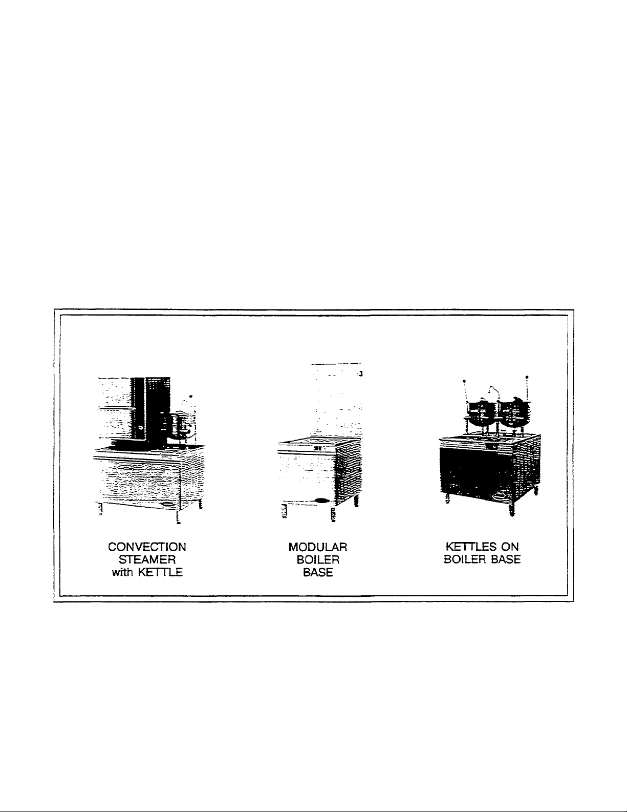
STEAMERS, STEAMER/KETTLES,
MODULAR BOILER BASES, and
KETTLES ON BOILER BASES
Cleveland Range Inc.
1333 East 179th St.
Cleveland, Ohio 44110
Phone: (216) 481-4900 • Telex: 98-0546 . FAX: (216) 481-3782
Garland Commercial Ranges • 1177 Kamato Rd.
Mississanga, Ontario CN L4W 1X4
Phone: (416) 624-0260 - FAX: (416) 624-0623

INSTALLATION INSTRUCTIONS FOR
FOR YOUR SAFETY
WARNING
WARNING
STEAMERS, STEAMER/KETTLES, MODULAR BOILER BASES, and
KETTLES ON BOILER BASES
Do not store or use gasoline or other flammable vapors and liquids in the
vicinity of this or any other appliance.
Cleveland Range equipment is designed and built to comply with applicable standards for manufacturers. Included among
those certification agenci es which have approved the safety of the equipment design and construction are: UL A.G.A. NSF,
ASME, CSA, CGA, and others.
Cleveland Range equipment is designed and certified for safe operation only when permanently installed in accordance with
local and/or national codes- Many local codes exist, and it is the responsibility of the owner and installer to comply with these
codes.
In no event shall Cleveland Range assume any liability for consequential damage or injury resulting from installations which
are not in strict compliance with our installation instructions- Specifically, Cleveland Range will not assume any liability for
damage or injury resulting from improper installation of equipment, including, but not limited to, temporary or mobile
installations.
INSTALLATION INSTRUCTIONS FOR ALL MODELS
1. These instructions must be retained by the owner/user for future reference. Gas-fired boilers are only to be installed in noncombustible
areas that nave provisions for adequate air supply- The term "boiler" will be used synonymously with "steam generator"
Installation of this equipment must be accomplished by qualified installation personnel, working
to all applicable local and national codes. Improper installation of this product could cause
injury or damage.
The flooring that will be directly under the boiler, must also be made of a
noncombustible material
2. Position: For proper operation and drainage, the equipment must be level, It should be placed next to an open floor drain. DO
NOT POSITION THE UNIT DIRECTLY ABOVE THE FLOOR DRAIN. Observe all clearance requirements to provide air
supply for proper operation, as well as sufficient clearance for servicing- The surrounding area must be free and dear of
combustibles. Dimensions and clearance specifications are shown on the specification sheet
3. Install in accor dance with local codes and/or the National Electric Code ANS1/NFPA No. 70-1987. Installation in Canada
must be in accordance with the Canadian Electrical Code CSA Standard C22.1. Equipment that is connected to electricity,
must be grounded by the installer . A wiring diagram is provided inside the base cabinet
4. The drain line outlet discharges exhaust steam and hot condensate. Connect 1 1/2" IPS piping (or larger) to extend the drain
line to a nearby open floor drain. Up to two elbows and six feet of 1 1/2 " IPS (or larger) extension pipe should be connected
to the drain termination. Drain piping extended six to twelve feet or using three elbows, should be increased to 2" IPS. No
more than two pieces of Cleveland Range equipment should be connected to one common drain line. The maximum length
of extension from the drain termination should not exceed six feet and use no more than two elbows. The extension piping
must have a gravity flow and vent freely to the air. This drain outlet must be free-vented to avoid the creation of back
pressure in the steamer cooking compartments. To ensure a vented drain line, DO NOT, UNDER ANY
CIRCUMSTANCES, CONNECT THE DRAIN OUTLET DIRECTLY TO THE FLOOR DRAIN OR SEWER LINE. Do
not run the drain line discharge into PVC drain piping or any other drain piping material not capable of sustaining 180°F
operation.
FAILURE TO OBSERVE THESE REQUIREMENTS CAN RESULT IN DAMAGE TO EQUIPMENT AND/OR THE
POSSIBILITY OF INJURY

• Direct-steam connected pressure steamers do not require a cold water connection, and therefore steps #5 and #6 do not apply. Refer
directly to step #7. A kettle fill faucet, if so equipped, requires a hot and/or cold water connection. The data contained in step #5 for
cold water also applies to hot water.
5. Connect COLD water supply plumbing to the line strainer. (Never connect hot water to the boiler's water fill line strainer) Constant flow
pressure must be maintained between 35 and 60 psi, and not experience a pressure drop below 35 psi when other appliances are used. If
the water pressure exceeds 60 psi, a pressure reducing valve must be installed in the water supply plumbing to reduce the water pressure to
less than 60 psi. Locations and pressure data are shown on the specification sheet. 1/4" IPS plumbing is sufficient for water supply lines up
to 20 feet in length, but water supply lines longer than 20 feet should be at least 3/8" IPS. Rush water supply lines thoroughly before
connecting them to the unit Use water which is low in total dissolved solids content and low in gas content to prevent internal scaling,
pitting and corrosion of the steam generator, and carry-over of minerals into the steam. Water which is fit to drink can still contain highly
detrimental impurities.
NOTE: If equipped with a kettle and kettle water fill swing spout, 3/8" (10mm) hot and/or
cold water connection(s)) will be required at the swing spout's valve.
6. Turn on the cold water supply to the unit. Ensure that the manual water valve, inside the base cabinet, is open.
7. Connect the primary fuel supply in accordance with the following instructions. Location and other data are shown on the specification
sheet
For Gas-Fired Steam Generators:
Post, in a prominent location, instructions to be followed in the event the user smells gas. This information shall be obtained by consulting
the local gas supplier. Install a sediment trap (drip leg) in the gas supply line, then connect gas supply piping to the boiler's gas valve
piping. GAS-FIRED EQUIPMENT IS DESIGNED FOR INSTALLATION ONLY IN NON-COMBUSTIBLE LOCATIONS. THIS
INCLUDES THE FLOORING THAT WILL BE DIRECTLY UNDER THE EQUIPMENT. Location, plumbing size, and pressure data are
shown on the specification sheet. Boilers rated at less than 225.000 BTU require 3/4" IPS gas supply piping, and boilers rated at 225,000
BTU or more require 1" IPS gas supply piping. Natural gas supply pressure must be between 4" -14" water column, and L.P. gas supply
pressure must be between 12" -14" water column. NEVER EXCEED 14" WATER COLUMN (1/2 psi) GAS PRESSURE. If the gas
supply pressure exceeds 14" water column, a pressure regulating valve must be installed in the gas supply plumbing to reduce the gas
pressure to less than 14" water column. Installation must be in accordance with local codes, or in the absence of local codes. with the
National Fuel Gas Code, ANSI Z223.1-1984. Installation in Canada must be in accordance with Installation Codes for Gas Burning
Appliances and Equipment B149.1 and B149.2. Use a gas pipe joint compound which is resistant to LP gas. Turn the gas valve's control
knob to "on" (the word "on" on the knob will be opposite the index on the valve's body). Test all pipe joints for leaks with soap and water
solution. Never obstruct the flow of combustion and ventilation air. Observe all clearance requirements to provide adequate air openings
into the combustion chamber. The appliance and its individual shut-off valve must be disconnected from the gas supply piping system
during any pressure testing of that system at test pressures in excess of 1/2 psi (14" water column or 3.45 kPa). The appliance must be
isolated from the gas supply piping system at test pressures equal to or less than 1/2 psi (14" water column or 3.45 kPa). A permanent 115
volt electrical connection is required at the junction box- The junction box location is shown on the specification sheet The unit must be
electrically grounded by the installer.
For Electric-Powered Steam Generators:
Connect electric power location and data are shown on the specification sheet. Provide connection as required by your unit; either directly
to the single contactor, or to the terminal block (when equipped with multiple contactors). Electric supply must match power requirements
specified on the data plate inside the base cabinet. The copper wiring must be adequate to carry the required current at the rated voltage. A
separate fused disconnect switch must be supplied and installed. The unit must be electrically grounded by the installer.
For Steam Coil Steam Generators:
Connect steam supply piping to the input side of the steam coil. Location and pressure data are shown on the specification sheet Incoming
steam pressure must be regulated between 35 and 45 psi. A 3/4" strainer, equipped with a 20 mesh stainless steel screen, must be supplied
and installed at the incoming steam connection point Hush the steam line thoroughly before connecting it to the boiler. To ensure an
adequate volume of steam, the branch steam supply line must be 3/4" IPS minimum. Connect the inverted bucket trap to the outlet end of
the steam coil. Fill the trap with water before installing it- A permanent 115 volt electrical connection is required at the junction box. The
junction box location is shown on the specification sheet The unit must be electrically grounded by the installer.
For Direct-Steam-Connected Steamers/Kettles:
Connect steam supply piping to the input side of the line strainer. Location and pressure data are shown on the specification sheet Rush the
steam fine thoroughly before connecting it to the steamer. To ensure an adequate volume of steam, the branch steam supply line must be
3/4" IPS minimum. (Direct-steam-connected kettles require 1/2" IPS pipe if the kettle's total capacity is 20 gallons or less, and 3/4" IPS
pipe if the total capacity exceeds 20 gallons.) A permanent 115 volt electrical connection is required at the junction box. The junction box
location is shown on the specification sheet. The unit must be electrically grounded by the installer. (Note: pressure steamers equipped
with strictly manual steam and drain valves do not require an electrical connection.)

8. Press the top of the power on-off rocker switch. The red indicator light in the switch will come on and the boiler will
begin to fill with water.
• Direct-steam-connected steamers are not equipped with self-generating boilers or "steam" switches. Ther efore, these
models do not require the 5-minute boiler water fill time, nor is it necessary to push a "steam" switch to produce
steam, as indicated in step #9. As soon as the pressure gauge on the control panel registers 10 psi (5 psi for pressure
steamers), preheating may begin. If you are operating a direct-steam-connected steamer, steps #9 and #10 do not
apply. Refer directly to step #11.
9. After about five minutes, the amber light in the "steam" switch will glow, indicating the water has reached a safe
operating level in the boiler. The "steam" switch can now be pressed (momentarily) in order to produce steam in the
boiler. This will activate the energy source (electric heaters, gas burners, or steam solenoid valve), and the amber light
will go out. The energy source cannot be activated until the boiler contains sufficient water, indicated by the amber
light. The "steam" switch must be pushed to re-start the steamer after it is shut off for any reason (including a
momentary power interruption). Do not attempt to start or operate this appliance during a power failure. Whenever the
amber light is illuminated, the-heater, steam supply, or burners are off, and no steam is being generated. (Note: for
units containing gas-fired boilers only: if the burners fai l to ignite in four seconds, a safety circuit will de-energize the
system. In this event, momentarily press the power switch to the "off' position, then back to the '"on" position. The
"steam" switch amber light should be on. Wait 5 minutes, then press the "steam" switch to start the burner ignition
cycle once again.)
10. Check to ensure that the water in the boiler's sight gauge glass automatically stays about 1/3 full when the boiler is
started up and operated.
11. Check to ensure that the steam pressure gauge registers 10 psi (5 psi for pressure steamers).
The steam pressure is factory-adjusted to provide the proper pressure. In some cases, however, the factory setting may
shift due to shaking in transit, and resetting will be required after installation. Proper adjustments and maintenance
procedures are detailed on a separate data sheet entitled "Steam Pressure Adjustments." Adjustments should be made
only by qualified service personnel. The factory pressure settings shown in the accompanying chart shoul d never be
exceeded.
12. When the installation is complete and free of teaks, refer to the Operating Procedures page, in order to check for proper
operation of the unit
GAUGE PRESSURE READING WITH NO STEAM FLOW (STATIC PRESSURE)
Equipment Steamer's
Steam Generator
only 5 psi.
Pressure Steamer N/A 5 psi 10 PSi 5psi 10 psi 30-45psi 5psi 12-45 psi
Pressure Steamer With
Any Kettle(s))
Steam Generator Only
TO psi
Kettle Only— All N/A 10 pa 15 pa N/A N/A N/A N/A 5-45psi
Convection Steamer
With or Without Kettles
Kettles
Self-Contained Steam Generator
Gas or Electric
Pressure
Reducing
Valve
N/A 5psi 10 psi 5psi 10 psi 30-45psi N/A N/A
5psi 10 psi 15 ps. 5 psi 10 psi 30-45psi 5psi 12-45 psi
N/A 10 pa 15 psi 10 psi 15 psi 30-45psi N/A N/A
N/A 10 psi 15 psi 10 psi 15 psi 35-45psi 10 psi 15-45psi
Operating
Pressure
Switch
high Limit
Safety
Pressure
Switch
Operating
Pressure
Switch
Self-Contained
Steam Coil Generator
High Limit
Safely
P ressure
Switch
"Kettles are to be connected to the "house" steam supply.
Steam
Supply
Pressure
Range
Direct-Connect (To
"House" Steam Supply
Steamer's
Pressure
Reducing
Valve
Steam
Supply
Pressure
Range

Data Sheet 260-TY
CLEVELAND CONVECTION STEAMER (MODEL C) OPERATING INSTRUCTIONS
Operation of the Cleveland Convection Steamer is very easy. Each operator should read and understand the following procedures to
effectively start, operate, and shutdown the steamer each day.
Start-up and Preheat
1. Check the cooking compartments to ensure that the steam tubes and drain screens are in place and secure. Check inside the steamer's
base cabinet to ensure that the manual drain valve is dosed and the manual water supply valve is open.
2. Press the top of the power on-off rocker switch located at the lower left of the control panel, under the steam pressure gauge. The red
indicator light in the switch will come on and the boiler will begin to fill with water.
• Direct-steam-connected steamers are not equipped with self-generating boilers or "steam" switches. Therefore, these
models do not require the 5-minute boiler water fill time. nor is it necessary to push a -steam" switch to produce steam. as
indicated in step #3 below. As soon as the pressure gauge on the control panel registers 10 pi. preheating may begin you
3. After about five minutes, the amber light in the steam switch will glow, indicating the water has reached a safe operating level in the boiler.
4. You can now preheat the cooking compartments). Cooking compartments should always be preheated before cooking
Note: With a steamer/kettle combination if both must be used at the same time, always heat the kettle first when kettle contents begin to
5. To preheat, close me compartment by gently swinging it shut. Set the electronic digital timer for one minute, in accordance with the following
are operating a direct-steam-connected steamer -skip" step #3, and refer directly to step #4.
The "STEAM" switch can now be pressed (momentarily) in order produce steam in the boiler. This will activate the energy source(electric
heaters gas burners, or steam solenoid valve). and the amber light will go out The energy source cannot be activated until the boiler contains
sufficient water, indicated by the amber light. The "STEAM" switch must be pressed to re-start the steamer after it is shut off for any reason
(including a momentary power interruption). No attempt should be made to operate equipment during a power failure. Whenever the amber
light is illuminated the heaters, steam supply or burners are off and no steam is being generated. (Note for steamers containing gas-fired
boilers only If the burners fail to ignite in four seconds, a safety circuit will de-energize the system In this event, momentarily press the power
switch to the position, then back to the “on" position. The "STEAM'' switch's amber tight should be on. Wait 5 minutes then press the
"STEAM"" switch to start the burner ignition cycle once again) In about 20 minutes the steam pressure gauge on the control panel should
register 10 psi
Simmer and steam pressure returns, the steamer compartments may be preheated
timer setting instructions. It will be several minutes before the time display begins to count down when the preheating is completed, the
steam will automatically shut off and a four-second alarm will sound.
Timer Setting
Each Convection Steamer compartment is equipped with an independent electronic digital timer, which has a maximum setting of 99 minutes,
Each timer is connected to a temperature sensing device in the cooking compartment. THIS SENSOR WILL ALLOW THE TIMER TO
COUNTDOWN ONLY WHEN THE INTERNAL COMPARTMENT REACHES PROPER COOKING TEMPERATURE. This assures uniformity in
the cooking times the operator will use as the timer automatically compensates for food product defrosting and/or heat-up time.
The timer can be set when the "COOKING TIME" display shows "00" (double zeros) which are illuminated continuously (not flashing). The two
small. Square pads below the timer display are pressed to set the timer. Press (1) to set one to nine (and zero) minutes for unit digits (single
minutes). Press (10) to set ten to ninety minutes for ten’s digit (multiples of ten minutes). Pressing continuously on either pad causes the digits
to change at a rate of 2 digits per second. It you pass the correct digit continue pressing the pad The display will cycle from "9" back to “0” then
continue upward again.
The timer is activated (and Steam enters the cooking compartment) when the “START/ cancel” pad is pressed. Red LED.lights glow in the
upper-left comer of the pad and the lower-right corner of the time display when the timer is activated. REMEMBER THE TIMER WILL BEGIN
TO COUNT DOWN ONLY AFTER THE COMPARTMENT REACHES PROPER COOKING TEMPERATURE. When the timer is counting down,
the red LED. Light continuously flashes on and off at the lower-right corner of the display. Once the pre-set time has counted down to zero, an
alarm will sound for four seconds, and the timer display will continuously flash "00” until the "start/CANCEL" pad is pressed.
Once the timer is activated, the time cannot be changed unless the “start/ CANCEL" pad is pressed- once pressed the pad's L.E.D. Will go out
any remaining time in the timer will be cancelled, and the display will show- "00"- not flashing. A new time setting can now be entered into the
Timer display.
EXAMPLE To cook for 14 minutes: Press the "start/CANCEL" pad to be sure the timer display shows "00” and is not flashing. Press the (10)
pad then release it when the “1" appears in the display. Press the (1)pad .and release it when the “4" appears m the display. Press the
"START/cancel” pad to start the timer (note the illuminated red L.E.D.’s in the pad and the time display). When the display counts down to zero.
a four second alarm will sound, and the display will flash "00" (the L.E.D.’s will go out). Press the “start/ CANCEL” pad to reset the timer,
shown by continuously illuminated "00' in the display (not flashing).
Automatic Cooking Operation:
To cook place pan of food in the compartment, set the desired cooking time and press the "START/cancel” pad. The timer will delay,
automatically compensating for defrosting and/or-food product heat-up time. If you have set the timer at 10 minutes, it may in fact take 11 or 12
minutes for the set time to expire and the alarm to sound. This is normal: the additional time was used to heat the compartment and food
product to cooking temperature. When the display counts down to zero, the four second alarm will sound, and the display will flash “00” (the
L.E.D.'s will go out). Press the "start/CANCEL." pad to reset the timer, shown by continuously illuminated '00" in the display
Manual Cooking Operator
If a cooking cycle longer than 99 minutes is desired, do not use the timer. Just press the "MANUAL OPERATION" pad located below the timer
to start the flow of steam. You roust press the pad again to shut off the Steam. A red LED. light in the upper-left corner of the pad illuminates
when the manual mode is activated, and Steam is flowing into the cooking compartment. THE TIMER CAN BE USED DURING THIS TIME. IT
WILL OPERATE AS STATED. EXCEPT IT WILL NOT TURN OFF THE STEAM AFTER THE ALARM SOUNDS.
The door may be opened for food inspection anytime during the cooking cyde, but KEEP Hands OUT OF THE COOKING COMPARTMENT TO
PREVENT BURNS. Optimum steam heat transfer, and therefore a higher quality of food product, is achieved when shallow, perforated
uncovered pans are used.
Boiler Shutdown:
The red-lighted power switch must be shut off for 3 minutes a minimum of once every 8 hours to automatically drain highly mineralized water
from the boiler, which reduces tne formation of scale.

OPERATION
DIRECT STEAM KETTLE
CARE AND CLEANING
Ensure that there is an adequate steam supply
to the kettle.
Turn the steam control valve to the full open
position by turning the knob counter-clockwise,
then allow the kettle to pre-heat.
NOTE: When cooking egg and milk products,
the kettle should NOT be preheated, as
products of this nature adhere to hot cooking
surfaces. These types of foods should be
placed in the kettle before heating is begun.
Fill kettle with product to desired level.
When the product has reached the desired
temperature, regulate the heat, as required, by
taming the steam control valve for less steam,
and therefore, a lower temperature.
When cooking is complete, dose the steam
control valve by turning the knob.
For kettle/steamer combinations: If the boiler in
a steamer is supplying steam to a kettle, always
heat the kettle first After the kettle contents are
heated, and the boiler's steam pressure returns
to normal, the steamer may be used. Pressure
steamer compartments should be sequentially
started, and preheated before cooking.
NOTE: As with cleaning food soil from any
cookware, an important pan of kettle cleaning is
to prevent foods from drying on. For this
reason, cleaning should be completed
immediately after cooked foods are removed.
Please refer to the "Care and Cleaning"
instructions for detailed kettle washing
procedures.
Your kettle must be cleaned regularly to
maintain its fast, efficient cooking performance,
and to ensure its cont inued safe, reliable
operation
WARNING: Do not use chlorine base
detergent.
1. Prepare a warm water and mild detergent
solution in the kettle.
2. Remove food soil inside the kettle using a
nylon brush. Do not use a metal bristle
brush, as this may permanently damage
the kettle's stainless steel surface.
3. Loosen food which is stuck to the kettle by
allowing it to soak at a low temperature
(simmer or low boil).
4. Tilt kettle forward to drain the wash water.
5. Rinse the kettle interior thoroughly, then
drain rinse water.
6. Leave the cover and draw-off valve open
when the kettle is not in use.
7. Using mild soapy water and a damp
sponge, wash the exterior of the kettle,
rinse and dry.
NOTE: For more difficult cleaning applications,
one of the following can be used: alcohol,
baking soda, vinegar, or a solution of ammonia
in water. Avoid the use of chloride cleansers,
which may damage the kettle's stainless steel
surface.
WARNING: Steel wool should never be used for
cleaning the cooking chamber of the kettle.
Particles of steel wool become embedded in the
cooking surface and rust, and may corrode the
stainless steel.
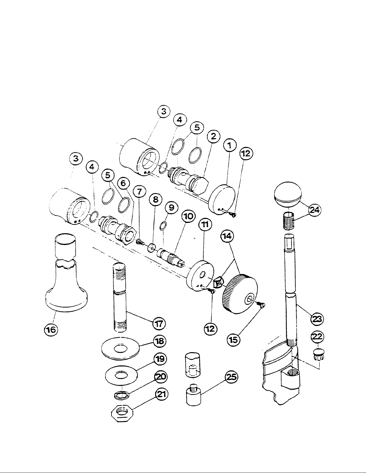
STEAM CONTROL
9201 REV:0
234-04DR

PARTS LIST - STEAM CONTROL
2
.
"O"Rin
g
"0"Rin
g
2
.
9201
REV:0
5
234-04TE
ITEM NO. PART NO. DESCRIPTION QTY.
1. KE50458 End cap, condensate return 1
KE50455-1 Trunnion, condensate return 1
3. KE50456 Trunnion housing 2
4-10. SE00011 Steam inlet trunnion assy. 1
4. FA00017 "O'Ring 2
5. FA00117
6. KE50460-1 Trunnion steam inlet 1
7-10. SE00029 Operating stem assy. stainless steel 1
7. FA11089 Screw, 8-32 x 1/4" 1
8. KE51713 Washer, operating stem 1
9. FA00110
10. KE50459 Operating stem, stainless steel 1
11. KE50457 End cap, steam inlet 1
12. FA11054 Screw, 6-32 x 3/8" 2
14. SE00028 Steam inlet knob assy. 1
15. FA11092 Screw, 8-32 x 1/2" 1
16. KE00200 Leg weldment ( 1 gal model) 2
KE00197 Leg weldment ( 6 gal model) 2
KE00198 Leg weldment (12 gal. model) 2
KE00199 Leg weldment (20 gal model) 2
17. KE50465 Service pipe ( 1 gal model) 2
KE52030 Service pipe ( 6 gal model) 2
KE50463 Service pipe (12 gal model) 2
KE50464 Service pipe (20 gal model) 2
18. KE50467 Washer, foot 2
19. FA30502 Washer, satin coat
20. KE51898 Washer, lock 2
21. FI00222 Lock nut, 1/2 NPS 2
22. KE50475 Plug button 1
23. KE50886 Handle ( 1 gal model) 1
SK50051 Handle ( 6,12 gal model) 1
KE50803 Handle (20 gal model) 1
24. KE50151 Knob 1
25. KE50474 Foot 1
4
1

OPERATING CONTROLS
14 23
-
234-OSTE
6
For your better understanding and confidence, the following explanation of the control system on this
kettle is offered.
ITEM NO. DESCRIPTION FUNCTION
Steam Inlet Knob
Turns the steam on or off to the kettle.
24
Tilting Handle
Used for tilting the kettle.

SERVICING GUIDE
BTU/HOUR
LBS./HOUR
H.P. 100,000
60
1.7 160.000
95
2.8
200,000
125 3.6 250,000
150 4.4
KW INPUT
18
KW 60
1.
7
24
KW 70 2.0 27
KW 90 2.6 36
KW 120 3.5
Remedy
9201
REV:0
7
This section contains information intended for use by Authorized Service Personnel onlv.
Probable Cause
1. Inadequate steam flow.
Remedy
Check for correct steam using chart below. If
kettle is connected to a -steamer and powered
by a generator the units should be operated
sequentially (kettle boiling first, then start
steamer).
PROBLEM : Kettle heats too slowly or does not come to a boil
2. Steam trap not operating property.
The trap should open periodically to dump
condensate, then dose. If it does no: open or
3. Food batches are not always the same.
close it should be cleaned or replaced.
When checking make certain that the original
state (ie. fresh or frozen) and quantity of food
product is the same.
B/ PROBLEM : The trunnion housing leaks steam.
Probable Cause
1. Trunnion "0" rings are worn-
Replace "0" rings.
STEAM FLOW RATING OF
STEAM GENERATORS
GAS INPUT STEAM OUTPUT BOILER
300,000 180 5.2
ELECTRIC
STEAM FLOW RATE
REQUIREMENTS FOR KETTLES
Capacity
Gal. / Lit.
5/17 11 9 6
10/42 22 18 11
25/95 55 44 28
40/151 88 70 44
60/227 132 105 66
Note: Above shows Ibs. per hour with 10-15 psig
steam at the kettle. The use of higher steam pressures
(20-25 psig) will reduce heat-up time 5 to 20 % .
Fast
Cooking
Medium
Speed
Cooking
Stock Kettle
48 KW 150
43
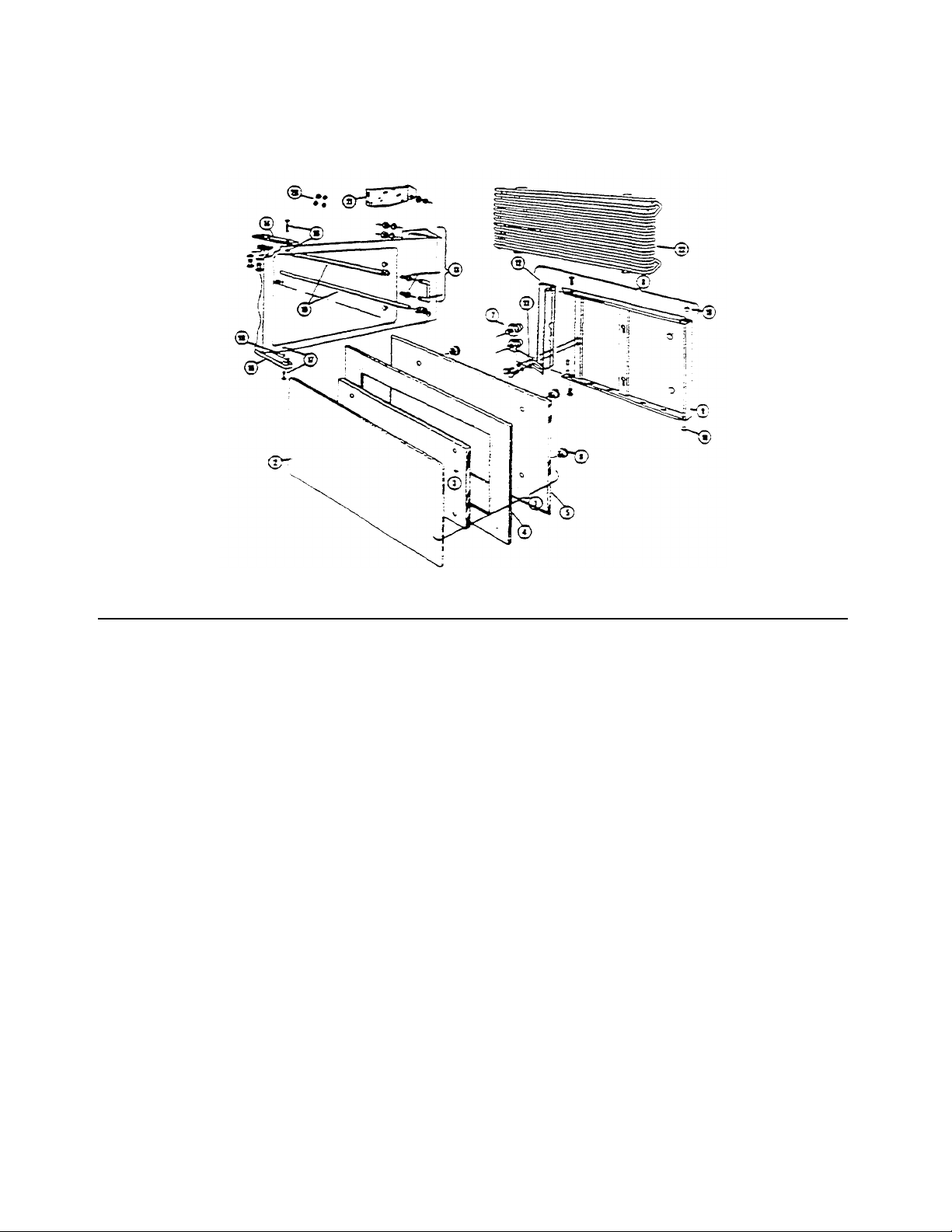
CONVECTION STEAMER MECHANICAL COMPONENTS
REFERENCE
NUMBER
PART
NUMBER
DISCRIPTION
2 44088
Gasket Retainer Plate
3
68214
Inner Gasket Reta
iner Plate
4 07138
Gasket
5
04171
Inner Door
6
14667
Knurled Finger Nut
1/4-20
7 88508
Inner Door Mounting Stud
8 44087
Outer Door Assembly
9 44088
O
UTER
Door Weldment
10 02089
Busting
(2
required)
11
69629
Door Spring
12
44167
Door Launch Assembly
58113
Door I
Latch less plastic; insert
&
screws)
70639
Plastic Insert (not shown)
19152
Pivot Screw
—
(2
required)
13 40878
Door Catch Assembly
14
58178
Upper Hinge Bracket (lower if door is hinged right)
15 58179
L
ower Hinge Bracket (upper i
f
door a hinged right)
16
40883
Upper Hinged Pin and
Retainer (lower if door is hinged right)
17
40884
Lower Hinge Pin and Retainer upper if door is hinged right
18
19552
Spacer
18
40783
Steam
—
Tube
20 15203
"0" Ring (4
required)
21 69298
Drain Screen
—
(After Dec 1,
1983)
Drain Screen (Before Dec.
1. 1983]
(Solid State Model "C" with Touch Control Timer Panel)
Data Sheet—261-EQ (R1))
1 44090 Inner Door Assembly
22 41423 Side Rack
CLEVELAND RANGE. INC. 1333 EAST 179th ST., CLEVELAND, OHIO 44110
LITHO IN U.S.A.
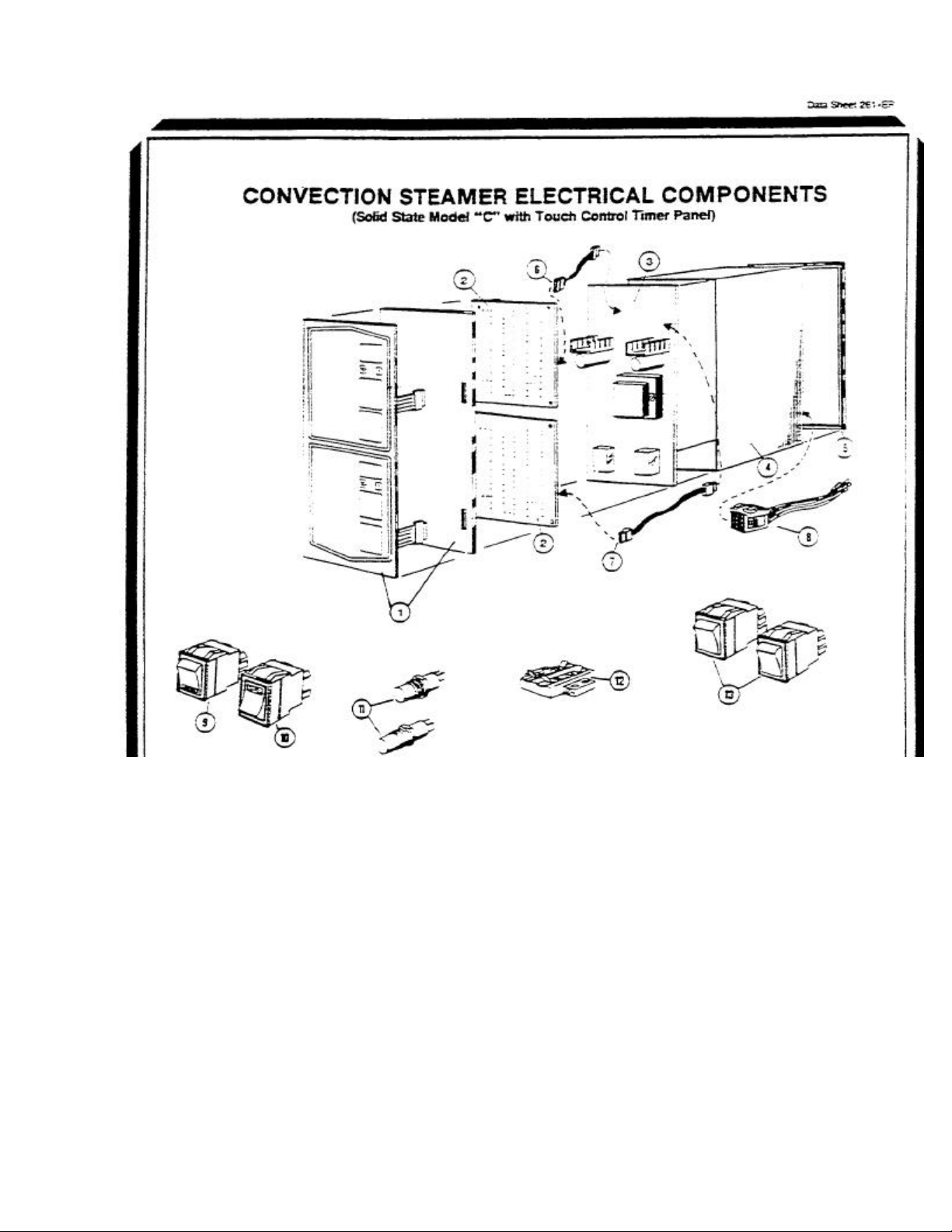
REFERENCE NUMBER PART NUMBER DESCRIPTION
1 45005 Control PaneL (Membrane Switch)
2 20479 Solid State Timer
3 16652 Power Supply Board
4 52595 Instrument Panel Enclosure
5 56228 Instrument Panel Frame
6 03002 9" Cable Assembly
7 03003 14" Cable Assembly
8 08135 Wire Harness
9 19993 DPDT Power Switch
10 19994 SPST Momentary Contact Reset Switch
11 19972 Thermostatic Switch
12 44168 Terminal Block. 2 pole
13 19992 DPDT Rocker Switch. Emergency Bypass
CLEVELAND RANGE, INC., 1333 EAST 179th ST., CLEVELAND, OHIO 44110
Manufacturer reserves right of design improvement or modification as warranted.
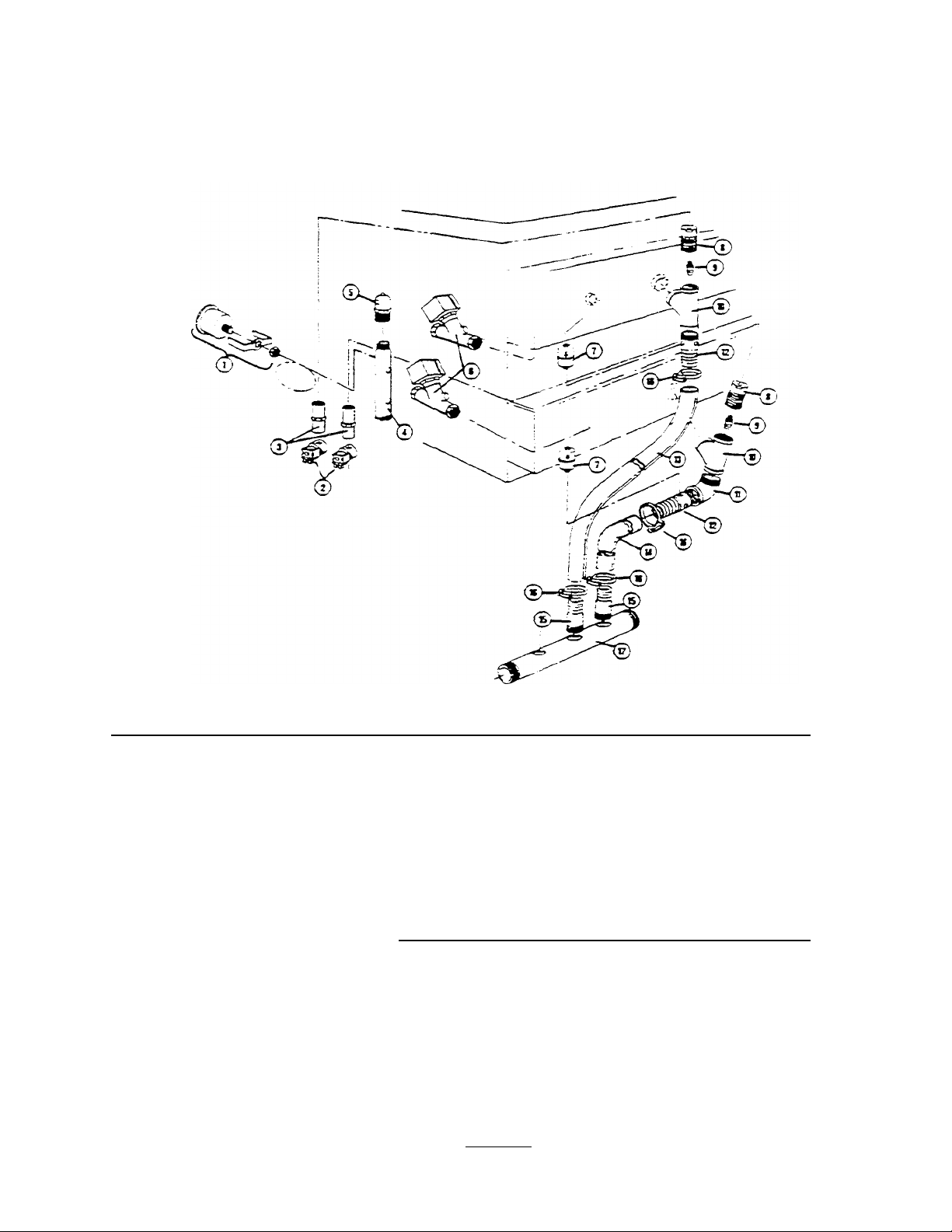
CONVECTION STEAMER PIPING COMPONENTS
(Solid State Model "C" with Touch Control Timer Panel)
REFERENCE NUMBER PART NUMBER DESCRIPTION
1 07168 Pressure Gauge
2 22218 Water Solenoid Valve
3 15455 Row Regulator. 1/2 GPM
4 13301 Steam Manifold
5 22226 AIR vent
6 22224 Steam Solenoid Valve
7 20559 Thermostatic Trap
8 06230 Reducing Bushing for Nozzle
9 14555 Nozzle Jet. Steam Condenser
10 02139 1" Y"
11 05227 1"" Street Elbow
12 56519 Compartment Drain Pitting (2 Holes)
13 70743 Tubing. 39" long
14 70742 Tubing. 28"' long
15 14481 Combination Hose Fitting (no holes)
16 03180 Hose Clamp
17 13252 Drain Manifold
CLEVELAND RANGE, INC., 1333 EAST 179th ST., CLEVELAND, OHIO 44110
Manufacturer reserves right of design improvement or modification as warranted.
 Loading...