

ClearSounds CSC600ER, XL-2055ER User Manual

CSC600ER; XL-2055ER
USER'S MANUAL

TABLE OF CONTENTS
FEATURE LIST.
SAFETY INSTRUCTIONS
SETTING UP
LOCATION OF CONTROLS
BASIC FUNCTION
FUNCTION OPERATION
PHONE BOOK
SET TIME . ................................
SET PHONE. ...............................
SET SOS. .................................
RECEIVING CALL RECORDS
REVIEWING DISPLAY MESSAGES
CALLER ID SYSTEM OPERATION
CALL ID ON CALL WAITING
TROUBLESHOOTING
AMPLIFY FEATURE
.............................
........................
..............................
......................
...........................
.......................
..............................
.....................
..................
..................
... ......... ........
.................... .....
.................... ......
2. The switch will be set to the position and the volume will be
1
2
set to middleatfactory.
3. Please adjust the volume to your necessary. Too loud volume may
hurt yourear. Werecommend you first move the switchtothe
position.
OFF
OFF
3
5
8
Using your Amplified Phone withhearingaids
Your phone can be used with hearing aids equipped with a telecoil(Tcoil). Adjust your hearing aid "T-switch" to the "T" position. Make sure
to hold the handsetcloseto your hearing aid.
11
11
13
13
15
CAUTION: This telephone can produce very high (loud) sound levels.
Repeated incremental exposure to amplification levels greater than
18 dB may be harmful to people without hearing loss. Always adjust
the volume controltothe minimum settingafter using thephone.
18
18
20
22
23
24
25
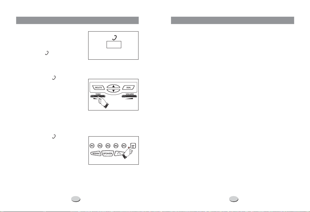
AMPLIFY FEATURE
Receiver Voice Tone
The unit provides extra amplification
in the tone frequency range you
need to boost. You can identify the
range follow these steps:
First, move the switch on the rear
of the unit to or position to
turn the function on or off. See
Figure1.
Then:
1. If you move the switch to
position, each time you use the
phone, the amplifier turns on
automatically, then you can adjust
the tone frequency range while on a
call by moving the control. See
Figure2.
But if necessary, you can press the
AMP
off the amplifier during a call. See
Figure3.
2. If you move the switch to
position, each time you use the
phone, the amplifier turns off
automatically.
But if necessary, you can press the
AMP
off the amplifier during a call. See
Figure3.
NOTES:
button will be bright.
ON OFF
ON
TONE
button to temporarily turn on or
OFF
button to temporarily turn on or
24
OFF ONOFF ON
Figure1
Figure2
Figure3
FEATURE LIST
1. FSK+DTMF dual system caller ID
2. Stores up to 99 incoming calls name & number,
date & time
3. Stores up to 30 outgoing calls number
4. Stores up to 99 names & numbers in phone book
5. LCD display calling name & number
6. Call back function
7. Delete individual or all records
8. Real time clock (Set time)
9. NEW call/ Message waiting LED indicator
10. Languages selection
11. 6 one-touch memories
12. 6 SOS numbers auto-dialing
13. SOS message recording
14. Battery low indicator
15. Last number redial
16. Flash time setting
17. Dialing mode setting
18. Speakerphone
19
. Caller ID on call waiting
20. LCD blue back light
. Timer
21
AMP1. When the amplifier turns on, the red indicator lamp near the
1

SAFETY INSTRUCTIONS
To reduce the risk of fire, electrical shock, and injury, please follow
these basic safety precautionsbefore you use thisequipment.
1. Carefullyread the instructions in this manual.
2. Follow all warnings and instructions markedontheunit.
3. When cleaning, unplug the telephone jack from the wall outlet.
Use a damp cloth. use liquid or aerosolcleaners.
4. Do not use this equipment near water eg, near a kitchen sink,
bathtub, washbowl, laundry rub, swimming pool or in a wet
basement.
5. Install in a protected location. Ensure all lines and cords are away
from foot traffic. place objectsonthe line cord that may
cause damage or abrasion.
6. Avoid spilling any liquid on the unit. This may cause internal
shorting, fireor shock and isnotcovered underyourwarranty.
7. Do not overload wall outlets and extension cords as this can
result in the risk of fire or electrical shock.
8. Never push objects of any kind into this telephone as they can
touch dangerous voltage points or short out parts that could
result in a risk of fire or electrical shock.
9. Take the phone to a qualified technician when it requires repair
work or service. To reduce the risk of electrical shock, do not
disassemble the telephone. Opening or removing covers can
expose you to dangerous voltages or other risks. Incorrect re-
assembly can cause electrical shock during subsequent use.
10. Avoid using the telephone during an electrical storm. There can
be a slight risk of electrical shockfromlightning.
11. use thetelephonetoreport a gas leak, if in the vicinity of
DO NOT
the leak.
12.Unplug this telephone from the wall outlet and refer servicing to
qualified service personnelunderthe following conditions:
If liquid is spilled into the unit.
l
If the unit is exposed to rain or water.
l
If the unit does not operate normally by following the Operating
l
Instructions.
If the unit is dropped or the casing is damaged.
l
If the unit exhibits a distinct change in performance.
l
DO NOT
DO NOT
2
BLANK OR
FAINT
SCREEN
CALLER ID
WILL NOT
WORK
PROPERLY
PHONE
WILL NOT
RING
NO DIAL
TONE
NO DATA
SENT
NO RESPONSE ON
LCD DISPLAY
TROUBLESHOOTING
If you are have problems with your phone, please check
below for helpful hints:
Check the line cord. Connect Telephone Cord. Check
l
batteries
Call your telephone company to verify that your Caller ID
l
services are active.
You may have too many communicationdevices hooked
l
to a single line. A communication device can be a phone,
modem, or facsimile (FAX) machine. Contact your
telephone company for help in calculating the limit for
your residence orbusinessline.
Verify that theLineCord is plugged in correctly.
l
Verify that the Line Cord connection is correct and tightly
l
secured.
Call your telephone company to verify that your caller ID
l
services are active.
If you have an answering machine connected to this
l
Phone, ensure that your answering machine is set to
answer after at least two rings.
You answer thecallbefore two rings.
l
Contact your telephone company if the problem
l
continues for more than 24 hours. The telephone company
may be experiencing temporary line
If you have experienced a power failure when using
l
optional AC adapter, the batteries for memory back up
could become weak or dead. If the power is restored and
the display screen does not respond then you must replace
the batteries with new.
23

CALLERIDONCALLWAITING
When you subscribe to Caller ID/Call Waiting service from
your local telephone company and you activate the call
waiting function, the telephone will display the name and
number of the second caller while you are having a
conversation.
Caller ID info displayed
Caller 1
436-1234
1. When you are on the line, the telephone will display the
name and number of the second caller.
2. Press the button to answer the second caller.
CALL WAITING
3. When you have finished, press the button to
continue with your conversation with the first caller.
Caller two's information
is displayed
Caller 1
4
Caller 2
291-5678
CALL WAITING
SETTING UP
CHECK THE CONTENTS OF THE BOX
Box should contain:
l
Handset with handset cord and phone base
l
Telephone line cord
l
4 AAA size 1.5V batteries
l
User's manual
l
Adapter
BATTERY AND ADAPTER INSTALLATION
A. The Caller ID phone requires four 1.5V AAA size batteries for LCD
display.
1. Remove the battery cover from the back of your Caller ID phone.
2. Insert four 1.5V AAA size batteries by observing the +/- polarity
marked on the compartment.
3. Replace battery compartment cover.
NOTES
:
1. Do not recharge the batteries or dispose them in fire.
2. Do not throw the battery everywhere, in case cause the
pollution.
B. You can also insert the adapter for the LCD display, and you must
insert the adapter for LCD back light and other special functions,
please refer to the concrete requirement in the manual.
CONNECTING LINE CORDS
1. Plug one end of the supplied modular cord into the line jack. Then
plug the other endintotelephone line jack.
2. Insert the earphone plug into the 2.5mm standard socket or the
3.5mm standard socket.
3. Insert the end of the shakerlineinto the socket.
NECKLOOP
22
3
 Loading...