

Page 1

Installation & Operation Manual
Audio Products
V-There™ 2000, 2100, and 2200
Video Conferencing System
Page 2

ClearOne Communications ~ www.clearone.com
ii
© 2002 ClearOne Communications, Inc. All rights
reserved. No part of this document may be
reproduced in any form or by any means without
written permission from ClearOne
Communications, Inc. Printed in the United States
of America. ClearOne Communications, Inc.
reserves specific privileges. Information in this
document is subject to change without notice.
V-There Installation and Operation Manual
ClearOne Part No. 800-170-101
June 2002 (Rev. 2.0)
Page 3

ClearOne Communications ~ www.clearone.com
iii
V-There Installation and Operation Manual
CHAPTER 1. Introduction . . . . . . . . . . . . . . . . . . . . . . . . . . . . . .1
Features . . . . . . . . . . . . . . . . . . . . . . . . . . . . . . . . . . . . . . . . . . . . . . . . . . . . . . . .1
Professional Services Group . . . . . . . . . . . . . . . . . . . . . . . . . . . . . . . . . . . . . . . . . .2
Technical Services . . . . . . . . . . . . . . . . . . . . . . . . . . . . . . . . . . . . . . . . . . . . . .2
Sales and Customer Service . . . . . . . . . . . . . . . . . . . . . . . . . . . . . . . . . . . . . .2
ClearOne Communications EuMEA . . . . . . . . . . . . . . . . . . . . . . . . . . . . . . . . .2
Product registration . . . . . . . . . . . . . . . . . . . . . . . . . . . . . . . . . . . . . . . . . . . .2
Product returns . . . . . . . . . . . . . . . . . . . . . . . . . . . . . . . . . . . . . . . . . . . . . . .2
Using this manual . . . . . . . . . . . . . . . . . . . . . . . . . . . . . . . . . . . . . . . . . . . . . . . . .3
Scope of the manual . . . . . . . . . . . . . . . . . . . . . . . . . . . . . . . . . . . . . . . . . . . .3
Terminology . . . . . . . . . . . . . . . . . . . . . . . . . . . . . . . . . . . . . . . . . . . . . . . . . .3
CHAPTER 2. Getting Started . . . . . . . . . . . . . . . . . . . . . . . . . . . .5
Unpacking . . . . . . . . . . . . . . . . . . . . . . . . . . . . . . . . . . . . . . . . . . . . . . . . . . . . . .5
North American users . . . . . . . . . . . . . . . . . . . . . . . . . . . . . . . . . . . . . . . . . . .6
Positioning the V-There . . . . . . . . . . . . . . . . . . . . . . . . . . . . . . . . . . . . . . . . . . . . .6
Before you install . . . . . . . . . . . . . . . . . . . . . . . . . . . . . . . . . . . . . . . . . . . . . . . . .6
Hardware setup . . . . . . . . . . . . . . . . . . . . . . . . . . . . . . . . . . . . . . . . . . . . . . . . . .7
Connector description . . . . . . . . . . . . . . . . . . . . . . . . . . . . . . . . . . . . . . . . . . .7
Power supply . . . . . . . . . . . . . . . . . . . . . . . . . . . . . . . . . . . . . . . . . . . . . . . . .9
Composite monitor . . . . . . . . . . . . . . . . . . . . . . . . . . . . . . . . . . . . . . . . . . . . .9
AccuMic II microphone setup . . . . . . . . . . . . . . . . . . . . . . . . . . . . . . . . . . . . .9
CHAPTER 3. Controlling V-There . . . . . . . . . . . . . . . . . . . . . . . . .13
Using the remote control . . . . . . . . . . . . . . . . . . . . . . . . . . . . . . . . . . . . . . . . . . . .13
Navigating with the remote control . . . . . . . . . . . . . . . . . . . . . . . . . . . . . . . . .13
Using the keyboard . . . . . . . . . . . . . . . . . . . . . . . . . . . . . . . . . . . . . . . . . . . . . . . .15
Table of Contents
Page 4

ClearOne Communications ~ www.clearone.com
iv
CHAPTER 4. Camera . . . . . . . . . . . . . . . . . . . . . . . . . . . . . . . . .17
About the camera . . . . . . . . . . . . . . . . . . . . . . . . . . . . . . . . . . . . . . . . . . . . . . . . .17
Detaching the camera . . . . . . . . . . . . . . . . . . . . . . . . . . . . . . . . . . . . . . . . . . .17
Camera control . . . . . . . . . . . . . . . . . . . . . . . . . . . . . . . . . . . . . . . . . . . . . . . . . . .18
To manually control the main camera . . . . . . . . . . . . . . . . . . . . . . . . . . . . . . . .18
To manually control the far-end camera . . . . . . . . . . . . . . . . . . . . . . . . . . . . . .19
To use an auxiliary camera . . . . . . . . . . . . . . . . . . . . . . . . . . . . . . . . . . . . . . .19
Camera presets . . . . . . . . . . . . . . . . . . . . . . . . . . . . . . . . . . . . . . . . . . . . . . . . . . .19
To create a camera preset . . . . . . . . . . . . . . . . . . . . . . . . . . . . . . . . . . . . . . . .19
To name a camera preset . . . . . . . . . . . . . . . . . . . . . . . . . . . . . . . . . . . . . . . . .20
To select a preset . . . . . . . . . . . . . . . . . . . . . . . . . . . . . . . . . . . . . . . . . . . . . .20
CHAPTER 5. Configuration . . . . . . . . . . . . . . . . . . . . . . . . . . . . .21
Configuring V-There . . . . . . . . . . . . . . . . . . . . . . . . . . . . . . . . . . . . . . . . . . . . . . .21
LAN setup . . . . . . . . . . . . . . . . . . . . . . . . . . . . . . . . . . . . . . . . . . . . . . . . . . . . . .22
Optimal settings for LAN calls . . . . . . . . . . . . . . . . . . . . . . . . . . . . . . . . . . . . .22
Video quality on the first call . . . . . . . . . . . . . . . . . . . . . . . . . . . . . . . . . . . . . .22
Required information . . . . . . . . . . . . . . . . . . . . . . . . . . . . . . . . . . . . . . . . . . .23
To configure LAN (DHCP) . . . . . . . . . . . . . . . . . . . . . . . . . . . . . . . . . . . . . . . .23
To configure LAN (non-DHCP) . . . . . . . . . . . . . . . . . . . . . . . . . . . . . . . . . . . .24
Gatekeeper (H.323) setup . . . . . . . . . . . . . . . . . . . . . . . . . . . . . . . . . . . . . . . . . . .25
To set up the gatekeeper . . . . . . . . . . . . . . . . . . . . . . . . . . . . . . . . . . . . . . . . .25
ISDN setup . . . . . . . . . . . . . . . . . . . . . . . . . . . . . . . . . . . . . . . . . . . . . . . . . . . . .26
Required information . . . . . . . . . . . . . . . . . . . . . . . . . . . . . . . . . . . . . . . . . . .26
ISDN settings . . . . . . . . . . . . . . . . . . . . . . . . . . . . . . . . . . . . . . . . . . . . . . . . .27
Phone directory . . . . . . . . . . . . . . . . . . . . . . . . . . . . . . . . . . . . . . . . . . . . . . . . . .28
To configure the phone directory . . . . . . . . . . . . . . . . . . . . . . . . . . . . . . . . . . .28
To place a call . . . . . . . . . . . . . . . . . . . . . . . . . . . . . . . . . . . . . . . . . . . . . . . .29
To add a phone number to the directory . . . . . . . . . . . . . . . . . . . . . . . . . . . . . .29
To edit a directory entry . . . . . . . . . . . . . . . . . . . . . . . . . . . . . . . . . . . . . . . . .29
To delete a directory entry . . . . . . . . . . . . . . . . . . . . . . . . . . . . . . . . . . . . . . . .29
Presentation settings . . . . . . . . . . . . . . . . . . . . . . . . . . . . . . . . . . . . . . . . . . . . . . .30
To add a presentation . . . . . . . . . . . . . . . . . . . . . . . . . . . . . . . . . . . . . . . . . . .30
To edit a presentation . . . . . . . . . . . . . . . . . . . . . . . . . . . . . . . . . . . . . . . . . . .30
To delete a presentation . . . . . . . . . . . . . . . . . . . . . . . . . . . . . . . . . . . . . . . . . .31
Page 5

ClearOne Communications ~ www.clearone.com
v
Audio settings . . . . . . . . . . . . . . . . . . . . . . . . . . . . . . . . . . . . . . . . . . . . . . . . . . . .31
To adjust audio preferences . . . . . . . . . . . . . . . . . . . . . . . . . . . . . . . . . . . . . . .31
To set compression . . . . . . . . . . . . . . . . . . . . . . . . . . . . . . . . . . . . . . . . . . . . .32
To adjust gain . . . . . . . . . . . . . . . . . . . . . . . . . . . . . . . . . . . . . . . . . . . . . . . . .33
Video settings . . . . . . . . . . . . . . . . . . . . . . . . . . . . . . . . . . . . . . . . . . . . . . . . . . . .33
Adjust video preferences . . . . . . . . . . . . . . . . . . . . . . . . . . . . . . . . . . . . . . . . .34
PIP . . . . . . . . . . . . . . . . . . . . . . . . . . . . . . . . . . . . . . . . . . . . . . . . . . . . . . . .37
Various advanced settings . . . . . . . . . . . . . . . . . . . . . . . . . . . . . . . . . . . . . . . . . . .37
Setting advanced preferences . . . . . . . . . . . . . . . . . . . . . . . . . . . . . . . . . . . . . .38
Troubleshooting . . . . . . . . . . . . . . . . . . . . . . . . . . . . . . . . . . . . . . . . . . . . . . .39
Download . . . . . . . . . . . . . . . . . . . . . . . . . . . . . . . . . . . . . . . . . . . . . . . . . . . .40
CHAPTER 6. Making Calls . . . . . . . . . . . . . . . . . . . . . . . . . . . . .43
Express Mode . . . . . . . . . . . . . . . . . . . . . . . . . . . . . . . . . . . . . . . . . . . . . . . . . . . .43
Placing a call . . . . . . . . . . . . . . . . . . . . . . . . . . . . . . . . . . . . . . . . . . . . . . . . .43
DTMF tones . . . . . . . . . . . . . . . . . . . . . . . . . . . . . . . . . . . . . . . . . . . . . . . . . .45
CHAPTER 7. Sending Data and Images . . . . . . . . . . . . . . . . . . . .47
Preparing a file . . . . . . . . . . . . . . . . . . . . . . . . . . . . . . . . . . . . . . . . . . . . . . . . . . .47
PCMCIA cards . . . . . . . . . . . . . . . . . . . . . . . . . . . . . . . . . . . . . . . . . . . . . . . . . . .47
To install a PCMCIA card . . . . . . . . . . . . . . . . . . . . . . . . . . . . . . . . . . . . . . . .47
Sending and receiving images . . . . . . . . . . . . . . . . . . . . . . . . . . . . . . . . . . . . . . . .48
Annex D images . . . . . . . . . . . . . . . . . . . . . . . . . . . . . . . . . . . . . . . . . . . . . . .48
Presentations . . . . . . . . . . . . . . . . . . . . . . . . . . . . . . . . . . . . . . . . . . . . . . . . . . . .49
V-There Application Conversion Wizard . . . . . . . . . . . . . . . . . . . . . . . . . . . . . .49
Sending presentations . . . . . . . . . . . . . . . . . . . . . . . . . . . . . . . . . . . . . . . . . . .51
About the web browser . . . . . . . . . . . . . . . . . . . . . . . . . . . . . . . . . . . . . . . . . . . . .52
APPENDICES . . . . . . . . . . . . . . . . . . . . . . . . . . . . . . . . . . . . . .53
Appendix A: Specifications . . . . . . . . . . . . . . . . . . . . . . . . . . . . . . . . . . . . . . . . . .53
Appendix B: ISDN error codes . . . . . . . . . . . . . . . . . . . . . . . . . . . . . . . . . . . . . . . .54
Normal causes . . . . . . . . . . . . . . . . . . . . . . . . . . . . . . . . . . . . . . . . . . . . . . . .54
Resource unavailable causes . . . . . . . . . . . . . . . . . . . . . . . . . . . . . . . . . . . . . .56
Service or option unavailable causes . . . . . . . . . . . . . . . . . . . . . . . . . . . . . . . .57
Service or option not implemented causes . . . . . . . . . . . . . . . . . . . . . . . . . . . . .58
Page 6

ClearOne Communications ~ www.clearone.com
vi
Invalid message causes . . . . . . . . . . . . . . . . . . . . . . . . . . . . . . . . . . . . . . . . . .58
Protocol error causes . . . . . . . . . . . . . . . . . . . . . . . . . . . . . . . . . . . . . . . . . . .59
Other causes . . . . . . . . . . . . . . . . . . . . . . . . . . . . . . . . . . . . . . . . . . . . . . . . . .59
Appendix C: Re-programming V-There via serial line . . . . . . . . . . . . . . . . . . . . . . . .59
Appendix D: Compliance statements and warranty . . . . . . . . . . . . . . . . . . . . . . . . . .60
North American users . . . . . . . . . . . . . . . . . . . . . . . . . . . . . . . . . . . . . . . . . . .60
FCC Part 68 requirements . . . . . . . . . . . . . . . . . . . . . . . . . . . . . . . . . . . . . . . .61
Canadian users . . . . . . . . . . . . . . . . . . . . . . . . . . . . . . . . . . . . . . . . . . . . . . . .61
European users . . . . . . . . . . . . . . . . . . . . . . . . . . . . . . . . . . . . . . . . . . . . . . . .62
Australian and New Zealand users . . . . . . . . . . . . . . . . . . . . . . . . . . . . . . . . . .63
End user warranty . . . . . . . . . . . . . . . . . . . . . . . . . . . . . . . . . . . . . . . . . . . . .63
Appendix E: Upgrading to V-There 2.0 . . . . . . . . . . . . . . . . . . . . . . . . . . . . . . . . . .65
Glossary . . . . . . . . . . . . . . . . . . . . . . . . . . . . . . . . . . . . . . . . . . . . . . . . . . . . . . . .67
Index . . . . . . . . . . . . . . . . . . . . . . . . . . . . . . . . . . . . . . . . . . . . . . . . . . . . . . . . . .73
Page 7

The V-There™ video conferencing system developed by ClearOne comprises a set-top
unit with a user-friendly software interface. Each screen in the V-There software can
be easily navigated using the specially designed handheld remote control or
keyboard.
V-There’s main function is the making and receiving of video conference calls.
V-There supports the H.320 (2100 and 2200 models only) and H.323 standards,
enabling you to make the following call types: Integrated Services Digital Network
(ISDN), 56K Restricted ISDN (ISDN-R, line rates in 56K multiples), local area
network (LAN), local area network-wide area network (LAN-WAN), and voice.
During H.320 ISDN and H.323 LAN calls, you can use V-There’s integrated
web browser to access Internet access and to exchange images or a sequence of
images with the person on your video call. This enables you to share web pages
and documents and make presentations while in a call.
The included AccuMic™ II delivers clean, high-quality conferencing audio
with Gentner
®
Distributed Echo Cancellation®, noise cancellation, and wide-
bandwidth digital audio technology.
CHAPTER 1: Introduction
ClearOne Communications ~ www.clearone.com
Features
• High-quality audio–data transfer rates to 768kbps for H.323 and 384kbps
(2200 model) or 128kbps (2100 model) for H.320 calls (V-There 2000 does
not support H.320).
• AccuMic II delivers award-winning audio. A second mic can be added for
larger venues.
• Graphics display support–VGA-SVGA display of video and graphics.
• XGA input for sharing PC graphics during presentations.
• Integrated web browser for viewing HTML documents.
• Easy-to-use user interface includes phone book with memory locations for
frequently-called numbers.
• Picture-in-picture provides viewing flexibility.
• Convenient control via infrared handheld remote and keyboard
• Wireless 802.11b support via optional PCMCIA card
Page 8

ClearOne Communications ~ www.clearone.com
Introduction ~ Professional Services Group
2
Product registration
Please register your V-There online by visiting ClearOne Technical Support at
www.clearone.com. When your product is registered, ClearOne Communications
is better able to serve you should you require technical assistance. Registration
information is also used to notify you of upgrades and new product information.
Professional Services Group
For additional help on how to install, set up, or operate the V-There, please contact
ClearOne Technical Services Group at the number below. We welcome your
comments so we can continue to improve our products and serve your needs.
If you need to return your V-There unit to ClearOne for service, please call the
Technical Services Group to obtain a return authorization number.
ClearOne Communications ~ 1825 Research Way ~ Salt Lake City, Utah 84117
Technical Services
Telephone: 1.800.283.5936 (USA) or 1.801.974.3760
Fax: 1.801.977.0087
E-mail: tech.support@clearone.com
Web site: www.clearone.com
Sales and Customer Service
Telephone: 1.800.945.7730 (USA) or 1.801.975.7200
Fax: 1.800.933.5107 (USA) or 1.801.977.0087
E-mail: sales@clearone.com
ClearOne Communications EuMEA GmbH
Leonhardstr. 16-18, D-90443 Nuremberg, Germany
Telephone: +49 911 955159-0
Fax: +49 911 955159-10
E-mail: global@clearone.com
Product returns
All product returns require a return authorization (RA) number. Please contact the
ClearOne Technical Services Group before attempting to return your V-There unit.
Page 9

3
Introduction ~ Using This Manual
To find information on a particular topic, consult either the table of contents or the
index. To obtain the definition of a term used in this manual, consult the glossary at
the back of this manual. To begin using V-There immediately, consult the Quick Start
Guide supplied with your V-There.
Scope of the manual
This manual deals with the operation of the V-There unit and its associated software.
Terminology
This section lists some of the terminology used in this manual and defines how these
terms are used within the context of the V-There.
Icon
The word icon always refers to an element on the V-There interface that you can
highlight and select.
Highlighting
Highlighting an icon or option on a drop-down list involves using the arrow buttons
to move the white box on the screen to the field, check box, or drop-down list that
you want to edit. Once you have highlighted the item you want, you usually have to
select it as well. For example: To add a new entry to the Phone Book, highlight and
select the Add icon.
Selecting
Pressing the Enter remote control button confirms the option or icon you have
highlighted and executes the required action. For example: Highlight and select the
Place a Call button in the interface. The Place a Call screen is displayed.
ClearOne Communications ~ www.clearone.com
Using This Manual
Page 10

ClearOne Communications ~ www.clearone.com
4
Page 11

When you unpack the V-There box contents, you should have the items below. If any
item is missing, please contact your supplier.
CHAPTER 2: Getting Started
ClearOne Communications ~ www.clearone.com
AccuMic II microphone
ISDN cables (1 for 2100 model,
3 for 2200, 0 for 2000; 830-170-
011, 830-170-012, 830-170-013)
Black Ethernet (LAN) cable
(830-170-001)
Yellow/black dual phono cable
(830-170-124)
SCART adapter block
(European customers only)
Audio/Video Products CD
(includes an electronic
version of the V-There
Installation and Operation
Manual)
Camera extension cable
(830-170-132)
Remote control and batteries
AccuMic II XFMR mini-DIN
10-pin (2) cable (830-156-002)
Gray serial cable (830-170-123)
Figure 2.1 Items included with V-There
Unpacking
S-video 6-ft (1.8 meter) cable
(830-170-020)
Keyboard remote and batteries
V-There main unit Power supply unit Power cord (Part 699-150-006
for US)
VGA extension cable
(830-170-133)
S-video camera extension
cable (830-170-136)
End user software license agreement and
Installation and Operation Manual (not shown)
Page 12

Getting Started ~ Positioning the V-There
6
Before using the V-There, please read the enclosed end user license
agreement—it contains important information concerning your use of the V-There
software. If you have the 2100 or 2200 model, please read the section on ISDN.
North American users
This equipment uses an S/T interface and is designed to connect to an external NT-1
terminal adapter (or optionally an NT-3, if you are using all three ISDN lines with a
V-There 2200). If your ISDN switch supplies a U interface, an external NT-1
terminal adapter must be used. Please contact your ClearOne distributor for
information about acquiring an external NT-1 or NT-3.
ClearOne Communications ~ www.clearone.com
ClearOne is not responsible
for product damage
incurred during shipment.
You must make claims directly with
the carrier.
!
Place the V-There main unit on a flat hard surface that allows adequate airflow
through the ventilation holes. Do not place the main unit in direct sunlight or near
sources of direct heat.
We recommend that you place the V-There on top of the video monitor. This
gives a more natural appearance to a video conference, since you will remain in
the line of sight of the camera. You will also be able to view the video image of the
person you are calling, without adjusting your position.
You can position the camera up to five meters (16.5 feet) away from the
V-There unit. Refer to page 17 for information about installing the camera
remotely.
The difference between the
V-There 2100 and 2200 is
that the 2200 features a
higher H.320 data rate (64384kbps vs. 64-128kbps). The
2000 model supports only H.323,
not H.320.
✍
Before you can begin using your V-There, you must connect the V-There to the
following:
• Power supply
• Monitor
• Microphone
• Audio speakers
• LAN and/or ISDN (w/ISDN interface)
• Camera w/infrared receiver (if the camera is being installed remotely)
Positioning the V-There
Before You Install
V-There uses an S/T ISDN
interface, requiring an
NT-1 or NT-3 adapter if
your network uses a U interface.
You can purchase an NT-1 or NT-3
through your ClearOne dealer.
✍
Page 13

7
Getting Started ~ Hardware Setup
All connections are made at the back of the V-There. The diagram above shows the
rear panel connections for the V-There 2200 model. For the 2100 model, the only
difference is that there is only one ISDN connector. The 2000 model has no ISDN
connector.
Before you begin to connect your V-There, ensure that the on/off switch is in
the Off state (down) and that the power supply has been connected to V-There.
The table below describes the purpose of each of the connectors on the rear
panel.
ClearOne Communications ~ www.clearone.com
You can also connect other devices to the V-There. For more information, see the
connection information on the following pages.
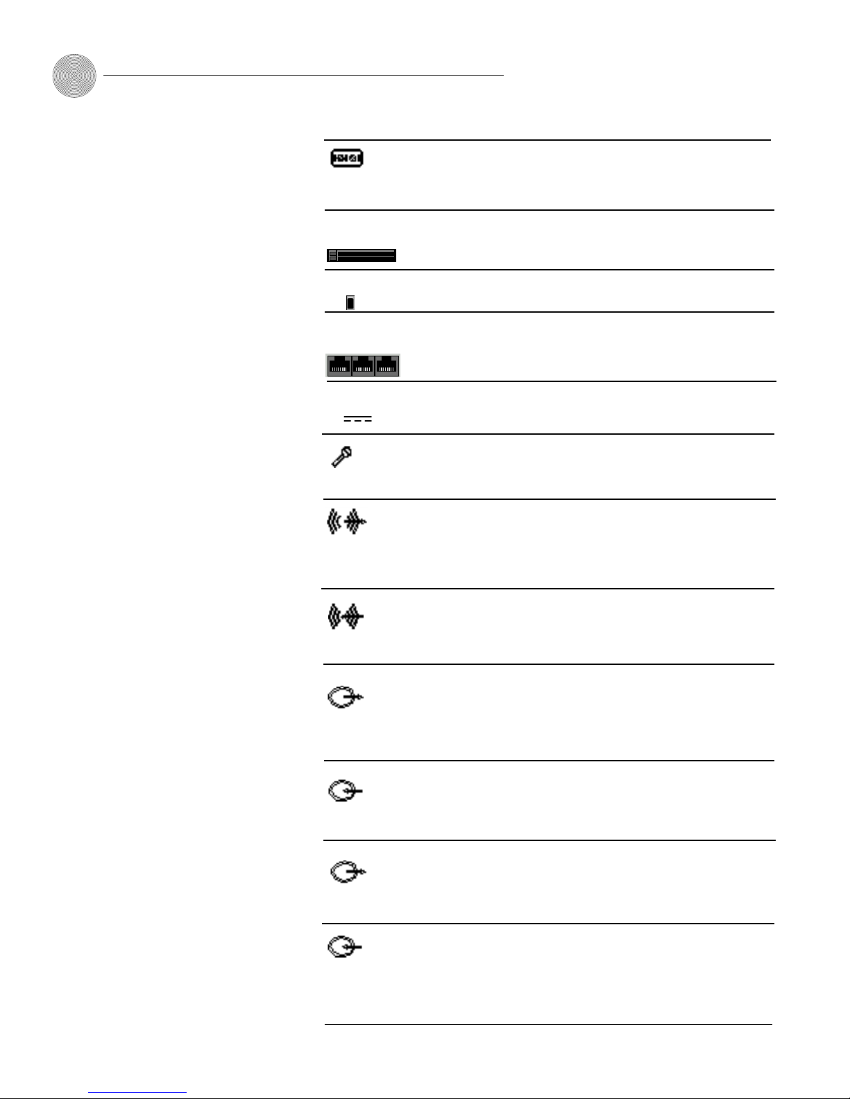
Connector Description
Ethernet
This connector provides video input from the V-There camera.
This connector provides power and PTZ capabilities for the main
camera and connection to the IR receiver.
If you want to use your V-There to make or receive calls over
your local area network (LAN), connect the gray Ethernet cable
to this connector.
Hardware Setup
Figure 2.2 Rear panel (2200 model shown)
Camera Control IR
Camera Video
The cable connectors are
color-coded to facilitate
straightforward
connection.
✍
Page 14
ClearOne Communications ~ www.clearone.com
Getting Started ~ Hardware Setup
8
Connector Description
If you want to connect external devices to the V-There—for
example, a PC to upload a software update—use the gray serial
cable to connect the device to the serial port.
If you want to use flash cards to upload information to your
V-There, remove the cover over the slot and insert the flash card.
This is the main on/off switch for your V-There.
Connect the ISDN cables labeled 1, 2, and 3 to the appropriate
connector. (The 2100 model has one ISDN cable and connector;
the 2000 model does not support ISDN.)
O/I Switch
ISDN S/T 1, 2,
and 3
Connect one end of the power supply unit to the DC 12V & 5V
connector.
Connect the AccuMic II microphone to the Mic connector.
Connect the powered audio speakers to this connector using the
3.5 mm phono cable. If the monitor has internal speakers,
connect directly to the monitor using the black connector on the
yellow/black dual phono cable.
If you want to use a line audio device such as a tape player,
connect the device to this connector.
If you are using a composite monitor, connect the yellow part of
the yellow/black dual phono cable to this connector. Then connect
the other end of the cable to the composite monitor.
If you want to use an auxiliary camera, connect the camera to
this connector.
If you are using an S-video monitor, attach the S-video cable to
this connector. Connect the other end to the monitor.
If you want to use an S-video-capable auxiliary camera, connect
the camera to this connector.
Mic
Audio In
Audio Out
Video In (RCA)
Video Out (RCA)
DC 12V and 5V
Video In (S-Video)
Video Out (S-Video)
Serial Ports
A and B
PCMCIA card slot
Page 15

9
Getting Started ~ Hardware Setup
Power supply
The V-There must be operated only with the power supply unit provided and must be
connected to a grounded power socket.
Composite monitor
V-There can be connected to a composite monitor. Depending on the V-There model,
you will need to connect it to either a National Television Standards Committee
(NTSC) monitor or a Phase Alternating Line (PAL) monitor.
If you are not sure how to connect external devices, see the instructions supplied
with your television or monitor.
European users can use the SCART block if the television comes with a SCART
connector. Using the supplied yellow/black dual phono cable, connect one end of the
cable with a yellow connector to the Video Out (yellow) connector on the V-There
and the black connector to the Audio Out (white) connector on the V-There. Connect
the other end of the cable with a yellow connector to the yellow video connector on
the SCART block and the black cable connector to the Audio (L/Mono) connector of
the SCART block. Connect the SCART block to the SCART connector on the
television.
ClearOne Communications ~ www.clearone.com
If a replacement power
supply is needed, it must
be obtained from an
authorized supplier of V-There
systems. Use of an unauthorized
power supply can be dangerous and
invalidates all warranties.
!
AccuMic II microphone setup
The AccuMic II mic pad features three microphone elements positioned to pick up
sound in a 360-degree pattern. Each mic element features noise cancellation,
automatic gating control, PA adaptive mode, adaptive ambient mode, and ClearOne’s
proprietary Gentner
®
Distributed Echo Cancellation®to make communication among
several people a natural, seamless experience. All of these functions operate
automatically and require no user adjustments.
VGA Monitor
Computer In
If you are using a VGA monitor, connect your monitor cable to
this connector.
Connect a computer to this XGA input to use presentations saved
on the computer.
Figure 2.3 AccuMic II
Page 16

ClearOne Communications ~ www.clearone.com
Getting Started ~ Hardware Setup
10
To install the AccuMic II
1. Plug the red connector on the supplied AccuMic II cable into the Mic
connector on the rear of the V-There unit (see Figure 2.4).
2. Attach the other end of the cable to the 10-pin connector on the AccuMic
II. Note that the AccuMic II receives its power from the V-There system; no
external power supply is needed.
3. Place the mic pad on a table or desk in the middle of your conference area,
away from walls and corners, for best acoustical performance.
The Mute button on the top of the microphone pad mutes all three mic
elements. Press the button once to mute the mic pad system; press it again to
unmute and resume the conference.
Optionally, you can connect a second AccuMic II pad to increase the capacity
of the video conferencing system (see page 11).
Figure 2.4 Microphone
installation
V-There
AccuMic II
Page 17

11
Getting Started ~ Hardware Setup
To install a second AccuMic II
The optional AccuMic II kit includes the mic pad and cable required to connect a
second AccuMic II to the system.
1. Connect the included cable to the 8-pin connector on the rear of the second
AccuMic II (see Figure 2.5).
2. Connect the other end of the cable to the 8-pin connector on the first
V-There mic pad.
3. Place the mic pads as far apart as possible on a table that is located in the
center of the conference area, away from walls and corners, for best
acoustical performance.
When two mic pads are used, they share mic gating information for optimum audio
clarity. Pressing the Mute button on either mic pad will mute both mic pads.
ClearOne Communications ~ www.clearone.com
8-Pin Connector
8-Pin Connector
8-Pin Connector
8-Pin Connector
10' (3-meter) Mini-DIN Cable
To Video
Codec
Extension AccuMic II
First AccuMic II
Figure 2.5 Connecting a second mic pad
The second AccuMic II
receives power through the
first one, eliminating the
need to connect a separate power
supply.
✍
8-Pin Connector
To Video
Codec
First AccuMic II
10' (3-meter) Mini-DIN Cable
8-Pin Connector
8-Pin Connector
8-Pin Connector
Extension AccuMic II
Page 18

ClearOne Communications ~ www.clearone.com
12
Page 19

The V-There interface is designed to be operated with the remote control and
keyboard.
To begin using your remote control and keyboard, open the panel at the back
of each and insert the two AA batteries supplied for each. Take care to insert the
batteries in the correct direction, as illustrated by the line drawings in the battery
compartment.
When replacing batteries, ensure that the new batteries are AA non-
rechargeable and always replace the entire set. If you mix used and fresh batteries,
you might damage your remote control or keyboard.
CHAPTER 3: Controlling V-There
ClearOne Communications ~ www.clearone.com
Using the Remote Control
Navigating with the remote control
The handheld remote (see Figure 3.1, page 14) control is factory programmed to
work with the V-There system. No user programming is necessary.
Navigating the onscreen interface with the remote control is easy; press the
arrow buttons and the Enter button.
You can also use the keyboard to navigate the V-There screens. For more
information on navigating with the keyboard, see the Using the Keyboard section
on page 15.
When you navigate the screen, a white box indicates your position on the
screen. When you have highlighted a field, icon, or drop-down list, press the Enter
button to select your choice.
Page 20

ClearOne Communications ~ www.clearone.com
14
Remote Control ~ Using the Remote Control
You must highlight the
screen item and press the
Enter button before the
V-There will execute an action.
✍
Navigation buttons
Power Puts V-There into sleep mode if you have selected the Power Save
Mode check box in the Adjust Various Advanced Settings/
Preferences section of Expert Mode. When this feature is
activated, the screen goes blank. The V-There is woken up by an
incoming call or by pressing any key.
Mute Allows a private conversation by muting audio such that the
participants at the far end cannot hear you.
Call Opens the Place a Call screen.
Hang-Up If you press Hang-Up during a call, it terminates the call.
Present Opens the Make a Presentation screen.
Help Opens the Help window.
Back Used as a backspace key in text fields.
Arrows Used for navigating the interface or moving the PTZ (pan, tilt,
zoom) camera.
Fwd Moves the cursor forward in a text field. Also moves the browser
forward to a previously-selected web page.
Zoom +/– Zooms the camera in and out. Pressing Zoom + makes image
larger, while pressing Zoom – makes it smaller.
Enter Confirms choice of a selection.
Volume +/– Increases or decreases the volume.
Menu Used for toggling between the onscreen menu and video display.
Far/Local Used for toggling camera control between the remote and local
camera views.
Snapshot Used for capturing a snapshot and sending a snapshot to the
far end.
Video Allows you to switch between the main camera and other video
devices connected to the system, such as a document camera.
PIP Allows you to switch to PIP (picture-in-picture) mode during a
call. Pressing this button repeatedly moves the PIP into each of
the four corners of the video image and then switches it off.
Numbers Used for entering numbers in the user interface.
Star Displays the camera presets. Navigate to the preset you want to
use and click Enter. During a call, this key displays the Camera
Presets list. Navigate to the preset you want to use and press
Enter.
Figure 3.1 Remote control
Page 21

ClearOne Communications ~ www.clearone.com
15
Remote Control ~ Using the Keyboard
The V-There keyboard is a full QWERTY keyboard. Below is a description of the
keyboard’s buttons.
Figure 3.2 Keyboard
A. Power Puts V-There into sleep mode if you have selected the Power Save
Mode check box in the Adjust Various Advanced Settings/Preferences section
of Expert Mode. The screen goes blank. The V-There is woken up by an
incoming call or by pressing the Power key.
Mode Selects between Express and Expert Modes. Express Mode is used
for placing calls and making presentations. Expert Mode is used for
configuring the system, in addition to making calls and accessing
presentations.
Far/Near Switches the camera control between the local and far-end
cameras.
Preset Opens the Preset window, where you select the camera preset you
want to use.
B. Call Opens a dialog box to select a destination to dial.
Hang-Up Disconnects a call.
Present Opens a dialog box that allows you to select a web page or
presentation.
Help Accesses the online help for assistance.
Menu Toggles the view between the onscreen menu and camera video.
Using the Keyboard
Figure 3.3 (A) Power, Mode, and Camera
Control keys
Figure 3.4 (B) Conference Control and
Menu keys
A. B. C.
D.
E.
Page 22

ClearOne Communications ~ www.clearone.com
16
Remote Control ~ Using the Keyboard
C. Snapshot Displays an image sent by the far end if Auto Display Snapshot is
not enabled. If a snapshot is currently displayed, pressing the Snapshot key
will clear the image and return the display of conference video. The
Snapshot key is also used to send images and presentations.
Video Toggles the view between the main camera and other video devices
connected to the system.
PIP Places a picture-in-picture (secondary) image on the screen.
Web Launches the V-There web browser.
D. Left Select Used with the navigation buttons to navigate and select items
in the web browser. Operates like the left button on a PC mouse.
E. Select Used with the navigation buttons to navigate and select items in the
web browser. Operates like the left button on a PC mouse.
Navigation This round, gray button is used for navigating the web browser.
Back Is used as a backspace key in text fields.
Zoom Zooms the camera video in and out.
Volume Increases and decreases the audio level.
Mute Mutes outgoing audio at the local site.
Function keys
The function (F) keys perform the following functions:
F1 Displays the help file
F2 Sleep mode
F3 Activates/deactivates audio mute
F4 Toggles between menu and video view on the monitor
F5 Displays the Phone Directory (Express Mode). Also
dials an ISDN number in the Place a Call mode
F6 Disconnects an ISDN or H.323 call
F7 Displays the Presentations screen (Express Mode)
F8 Captures and sends a snapshot to the far end
F9 Displays the Video Source list
F10 Allows PIP on the monitor
F11 Zooms the camera in
F12 Zooms the camera out
Figure 3.5 (C) Video Control keys
Figure 3.6 (D) Left Select key (left side of
keyboard)
Figure 3.7 (E) Navigation, Zoom, and Audio
control keys
Page 23

ClearOne Communications ~ www.clearone.com
CHAPTER 4: Camera
Your V-There comes complete with a high-quality detachable Canon camera.
The detachable camera is designed for use at up to five meters (16.5 feet) from
the V-There. The main advantage of a non-integrated camera is that it allows you to
position the V-There unit and the camera in separate locations if, for example, space
is limited.
Detaching the camera
1. Remove the cable cover by lifting up on the rear portion of the cover, as
shown in Figure 4.1.
The type of camera
supplied is either NTSC or
PAL compatible,
depending on the video standards
used in your area.
✍
About the Camera
2. If they are connected, disconnect the two camera cables from the Camera
Video and Camera Control +IR rear panel connectors.
3. Remove the screw at the back of the camera housing, as shown in Fig 4.2.
Figure 4.1 Lift off cable cover
Figure 4.2 Remove mounting screw at back
of camera housing
Page 24

ClearOne Communications ~ www.clearone.com
18
Camera Control
The camera included with your V-There is a PTZ camera, which means you can pan,
tilt, and zoom the camera.
To manually control the main camera
1. If the onscreen interface is displayed, press Menu to hide the menu and
display video full screen.
2. Using the arrow keys, position the camera in the desired location. If you are
in a call, refer to the picture-in-picture as you position the camera.
3. Use the Zoom + and Zoom - keys to adjust the video magnification.
Camera ~ Camera Control
4. Connect one end of the extension cable to the camera cable. Connect the
other end to the rear panel, as shown in Figure 4.3.
Figure 4.3 Plug camera extension
cable into V-There
5. Place the camera on top of the monitor, a desk, or a shelf such that the
front part of the camera housing just overhangs the support surface. Route
the camera extension cable as desired.
Page 25

ClearOne Communications ~ www.clearone.com
19
Camera ~ Camera Presets
To manually control the far-end camera
1. Press Far/Local to display the Remote Camera icon.
2. Use the arrow and zoom keys to position the far-end camera.
3. Press the Far/Local key again to return to controlling the local camera.
Please note that you will not be able to control the far-end camera until about 20
seconds after the call has connected.
To use an auxiliary camera
If you use a secondary camera (such as for documents) in addition to the main
camera, it is known as an auxiliary camera.
The type of auxiliary camera you can use depends on the main camera delivered
with the V-There. If the main camera is NTSC the auxiliary camera must be NTSC,
too. The same applies for PAL cameras.
1. Press Video to display the Video Source list.
2. Navigate to the auxiliary camera source and press Enter to select the
source.
This feature is available
only if it is also supported
by the video conferencing
system of the location you are
calling.
✍
Camera Presets
You can set up a number of preset positions for your camera. Each preset position
corresponds to a number between 0 and 9. When you select a preset, the camera will
immediately turn to point in the corresponding direction. V-There can store 10
presets (numbered 0-9) for the main camera.
To create a camera preset
1. Click the Presets tab in the Adjust Video Settings screen to display the
Camera Presets screen. To locate the Presets tab, click the Expert/Novice
Mode button on the keyboard until the Expert Mode menu is displayed (the
Expert System Setup button will be highlighted). Click the Expert System
Setup button, then the Adjust Video Settings button. Select the Presets tab.
Page 26

ClearOne Communications ~ www.clearone.com
20
To name a camera preset
1. Access the Preset screen as described previously. Select the Preset name and
press Enter.
2. Type in the name of the preset.
3. Press Enter to save the name of the preset.
To select a preset
1. Press either the * button on the remote control or the Preset key on the
keyboard. This opens the Camera Preset dialog box.
2. Using the up and down keys, navigate to the preset you want to use and
press Enter. The camera moves to the selected preset.
Camera ~ Camera Presets
Figure 4.4 Camera screen
2. Navigate to the number of the preset you want to set and press Enter.
3. Point the camera in the desired direction using the arrow buttons on the
remote control. Refer to the small (picture-in-picture, or PIP) video window
as you position the camera.
4. Use the Zoom + and Zoom - buttons to zoom the camera in and out, until
you are satisfied with the video image.
5. Press Enter to set the preset. A message will be displayed, confirming that
the preset has been stored.
Page 27

After you have finished making connections to the rear panel of the V-There, turn it
on using the switch on the back of the unit. The first time you power on the unit (or
after you reset the unit to factory defaults), it will initiate an onscreen configuration
wizard that walks you through the system setup.
You do not need to complete every step to begin using your V-There. For
example, if you choose to use your ISDN connection in the configuration wizard,
and will not be connecting the unit to a LAN, you do not need to complete the
configuration screens for network (LAN) setup.
After you complete the configuration wizard, you can make subsequent
adjustments in the Expert Mode of the user interface. To enter the Expert Mode,
press the Expert/Novice Mode button on the keyboard to display Expert System
Setup.
There are several occasions when you will use the Expert Mode:
• When you turn on your V-There for the first time
• After a software upgrade
• After resetting the V-There to factory defaults
• To add or edit phone directory entries or presentations
CHAPTER 5: Configuration
ClearOne Communications ~ www.clearone.com
Configuring V-There
The first time you turn on
your V-There, it will
initiate an onscreen
configuration wizard that walks you
through the initial system setup for
the network, gatekeeper, and ISDN.
✍
Refer to the sections on the
following pages after the
initial setup if you want to
change settings, or if you want
information about additional
settings not covered in the
configuration wizard.
✍
Page 28

ClearOne Communications ~ www.clearone.com
22
Configuration ~ LAN Setup
LAN setup is required if you want to make H.323 calls, use the browser, or remotely
access the unit for administration and troubleshooting.
Optimal settings for LAN calls
The V-There requires appropriate settings on the network switches and hubs used for
H.323 LAN calls. For a 384kbps LAN call, V-There will require more than 800kbps of
LAN bandwidth (400kbps in each direction) due to overhead on packets. Equally
important is that packets must be delivered with minimum jitter and delay. The network
administrator can take several steps to optimize the performance of LAN calls:
•
Proprietary bandwidth control techniques on hubs and switches should be
turned off—they can reduce traffic on high usage ports.
•
Use switches rather than hubs, if possible—switches increase throughput.
•
Ports used for V-There should be configured as 10Mbit full duplex. Auto-sense
of duplex should be disabled.
•
Any proprietary packet forwarding algorithms designed to improve file transfer
and conventional IP usage should be turned off—LAN video calls need simple,
real-time packet delivery.
•
Good quality Cat. 5 cable should be used. Poor quality cabling will not cause
problems with normal operations as packets are re-sent, but on a LAN call,
lost packets will show up as blocky video or audible noise.
•
The network segments being used by V-There should not be heavily loaded with
other network traffic.
Video quality on the first call
During the first LAN call after initial setup, the V-There will attempt to detect the
half/full-duplex setting of the connected switch or hub. It looks for errors on the
Ethernet line. As errors can occur with the correct duplex setting, the V-There
measures them over a period of time, switches its duplex mode, and re-measures the
error rate. It then selects the best duplex setting. For this reason, the first LAN call on
a new installation should be left up for three minutes if the video quality looks poor.
The V-There is factory set to use half-duplex.
The unit monitors packet loss during the first call after each power-up. If packet
loss is excessive, the V-There will switch duplex settings and re-check the packet loss. If
the new duplex setting reduces packet loss, the new setting is retained. Under normal
circumstances, the second power up on the same hub results in minimal packet loss.
LAN Setup
LAN setup is not required
if you will use ISDN
exclusively.
✍
Page 29

ClearOne Communications ~ www.clearone.com
23
Configuration ~ LAN Setup
Required information
Before you begin the LAN setup, it is recommended that you connect your V-There unit
to your LAN using the Ethernet (marked LAN) cable.
Network settings
To use V-There over a LAN, you need to know if the LAN uses Dynamic Host
Configuration Protocol (DHCP).
If the LAN does not use DHCP, you need the following information prior to LAN setup:
• The IP address to be assigned to the V-There
• The subnet mask
• The IP address of the default gateway
• The IP address of the Domain Name System (DNS) server, if you want to use a
DNS server for name lookup
• The IP address of the Windows Internet Naming Service (WINS) server, if you
want to use a WINS server for name lookup.
To configure LAN (DHCP)
1. If you are not in the Expert Mode, press the Mode key on the keyboard to
display the Expert Mode menu.
2. Click the Expert System Setup button (first menu button). This displays the
configuration toolbar.
3. Click the Adjust Communications Settings button. This opens the
Communications Settings window, with the Network screen displayed.
The Network section is where you establish the network settings your unit will use.
Figure 5.2 Network screen #1
Figure 5.1 Expert Mode menu
Page 30

ClearOne Communications ~ www.clearone.com
24
Configuration ~ LAN Setup
To be able to place a LAN
call or browse the
Internet, you must enter
the IP address of either the DNS
server or the WINS server on this
screen.
✍
4. The LAN Adapter drop-down list allows you to select between normal and
wireless LAN. If you have installed a wireless LAN card in the PCMCIA slot,
the adapter type will automatically appear in the list.
5. Select the DHCP check box if your network supports DHCP.
If your network supports DHCP, you do not need to enter any other settings. DHCP
automatically generates an IP address for the unit and your LAN setup is complete.
To configure LAN (non-DHCP)
1. Enter the IP address of the unit in the IP Address field.
2. Enter the IP address of the gateway in the Default Gateway field.
If you do not need external access from your local subnet, this field can
remain as 0.0.0.0.
3. Enter the subnet mask to be used in the Subnet field. If you are using a
static IP, you must use a default gateway.
4. If you use a DNS server for name lookup, select the DNS check box. The
DNS Server field is enabled.
5. Enter the address of the DNS server in the DNS Address field.
6. If you use a WINS server for name lookup, select the WINS check box
rather than the DNS check box. The WINS Server field is enabled.
7. Enter the address of the WINS server in the WINS Server field.
8. Enter the LAN name in the field provided. Press Enter to confirm changes.
9. Click the More button to open the second Network screen.
10. Enter the network user logon name in the Logon User ID field.
Figure 5.3 Network screen #2
IP addresses must be
unique on your local
network. Duplicate addresses result in unpredictable and
unforeseen network problems.
✍
V-There supports Lucent
Technologies and Symbol
Technologies wireless
LAN cards.
✍
Page 31

ClearOne Communications ~ www.clearone.com
25
Configuration ~ Gatekeeper (H.323) Setup
The function of the gatekeeper is to verify the destination address of a call prior to
allowing the call to proceed. It also controls bandwidth usage so the network isn’t
overloaded and it provides convenient address translation of the far-end conferencing
system in a call.
Select the Gatekeeper tab in the Adjust Communications Settings section and
press the Enter button. The Gatekeeper window opens.
Gatekeeper (H.323) Setup
Figure 5.4 Gatekeeper screen
To set up the Gatekeeper
1. Select the gatekeeper mode from the Mode drop-down list. Select from None
(no gatekeeper will be used), AutoDetect (the unit automatically detects and
selects the gatekeeper), or Explicit (you enter the IP address of the
gatekeeper).
2. If you selected the Gatekeeper Mode of Explicit, enter the IP address of the
gatekeeper in the Address field.
If using a gatekeeper, both
the E164 and Alias
(H.323) IDs must be
entered.
✍
11. Enter the password that you use for logging on to the network in the Logon
Password field. When you enter a password in this field, a * is used to
represent each character of the password so that the password is not visible
to other people.
12. Enter the network domain your password gives access to in the Domain
Name field. If you do not know the domain, ask your system administrator.
13. If you are using a proxy server, select the Use a Proxy Server check box and
enter the appropriate address and port information in the fields provided.
You do not need to
complete the Gatekeeper
settings screen unless your
network uses H.323 gateways and
gatekeepers.
✍
Page 32

ClearOne Communications ~ www.clearone.com
26
Configuration ~ ISDN Setup
3. Enter the alias (H.323) name in the Alias Name field if your gatekeeper
software contains an H.323 name.
4. Enter the E164 name in the E164 Name field if your gatekeeper software
contains an E164 name. This is essential to receive calls from an H.320
system via gateway.
5. Select the rate you want to use.
6. Enter the delimiter in the Delimiter field that the gatekeeper is to use when
placing nx64k calls. Your system administrator sets a symbol or digit as the
delimiter.
7. Enter the prefixes that your gateway uses to place specific types of
LAN/WAN calls in the 128K field, 384K field, etc. for the rate you are
using. If these prefixes are not configured, the LAN-WAN call type is not
available when making a call.
If you do not use a gateway, these fields can remain blank.
Required information
Before you begin the ISDN setup, it is recommended that you connect your V-There
unit to your ISDN connection using the supplied ISDN cable(s). The number of
cables that you need will depend on the number of ISDN channels that are available
to you and are supported by the V-There model. You will need one ISDN cable if you
are using the 2100 model and up to three if you are using the 2200 (ISDN cables
are included with these models).
The following section lists the information required for completing the ISDN
Settings screen:
• The type of ISDN exchange (or switch type) to which V-There is to be connected
• The local ISDN numbers for the lines to be used. These must be entered in the
proper order.
• Whether the ISDN network is restricted to a multiple of 56K (ISDN-R, nx56K)
• SPID information
• Any prefixes or other specialized information to access long-distance calling on
ISDN lines.
This information should be available from your system administrator or telephone
company.
ISDN Setup
The V-There connects to an
ISDN network via an S/T
interface. An optional
(required for U interfaces) NT-1 or
NT-3 adapter is available through
your ClearOne distributor.
✍
The V-There 2000 does not
support ISDN operation.
✍
Page 33

ClearOne Communications ~ www.clearone.com
27
Configuration ~ ISDN Setup
ISDN settings
This section describes how to configure your unit to make calls over an ISDN
connection.
1. Navigate to the ISDN tab in the Adjust Communications Settings section of
the user interface and click the Enter button. Select the ISDN tab to display
the ISDN settings screen.
2. Select the ISDN switch type to which the unit is to be connected from the
Switch Type drop-down list.
3. Enter the local ISDN line numbers in Line 1 to Line 6 fields.
The number of ISDN numbers that you need to enter depends on how many
ISDN channels you are using. You need to enter two numbers for each of the
one, two, or three bonded telephone lines, in order to obtain 2B (128kbps),
4B (256kbps), and 6B (384kbps) bonded calls respectively.
For National ISDN 1 or DMS100, the full 10-digit number must be entered.
For other switches and localities, the area code should be omitted.
4. If the local ISDN switch is an ISDN-R 56K restricted network, select the
Restricted Network check box.
5. If you selected National ISDN 1 or Nortel DMS100 from the Switch Type
drop-down list, the SPID 1-6 button appears. Click it to open the SPIDs
screen (see Figure 5.6 on page 28). Select the Auto Detect SPIDs check box
(the unit detects your SPIDs automatically) unless you know that your
SPIDs are an unusual configuration; then enter them manually. If you
entered the ISDN numbers in the previous screen, you can click Auto Fill to
have them automatically transferred to the SPIDs number boxes. You will
need to reboot the unit to save these changes.
Figure 5.5 ISDN settings screen
If you know that your
SPIDs are an unusual
configuration, deselect the
Auto Detect SPIDs check box and
enter the SPIDs manually in the
SPID fields.
✍
A bonded call uses special
hardware (IMUX) to bond
the ISDN lines into a
single logical channel. V-There can
dial bonded calls at rates of
128kbps, 192kbps, 256kbps and
384kbps. For a bonded call, you
must enter only a single destination
number when making a call.
✍
An unbonded call treats
multiple ISDN lines as
single channels. Each line
is 64kbps. You can dial a call with a
rate of 1x64kbps, 2x64kbps, and so
on, up to 6x64kbps. When making
an unbonded call, you need to enter
an ISDN number for each ISDN
line you are using.
✍
An ISDN-R call is
transmitted at a rate that
is a multiple of 56kbps.
This rate is used in some countries
where channel bandwidth is limited
to 56kbps. An ISDN-R call can also
be bonded.
✍
Page 34

ClearOne Communications ~ www.clearone.com
28
Phone Directory
The Phone Directory allows you to store numbers for easy retrieval when you want to
make calls.
To configure the Phone Directory
Navigate to the Place a Call button in the Expert Mode toolbar and click it. This
opens the Directory screen.
This screen allows you to place calls, add entries to the directory, edit entries, and
delete them.
Figure 5.7 Directory screen
Configuration ~ Phone Directory
Figure 5.6 SPIDs screen
Page 35

ClearOne Communications ~ www.clearone.com
29
Configuration ~ Phone Directory
To place a call
1. Navigate to the destination you want to call (in either Expert or Express mode)
in the Phone Directory screen and press the Enter key.
2. Click the onscreen Call button.
The unit dials the call.
3. Press Hang-Up on the remote control to disconnect the call.
To add a phone number to the directory
1. Click the Add button. This opens the Phone Book Entry window.
2. Select the call type in the Type drop-down menu. If you select ISDN-R or voice,
the unit will reduce the rate in the Rate field if it is set too high for the call type
you select.
3. Select the rate in the Rate window, if necessary.
4. Enter the name of the destination in the Name field.
5. Enter the phone number(s) in the Line field(s).
6. Click Save to save the settings.
To edit a directory entry
1. Select the phone book entry you want to edit.
2. Click the Edit button. This opens the Phone Book Entry screen.
3. Navigate to the fields or menus you want to edit and make the changes you
want to make.
4. Click Save to save changes and exit.
To delete a directory entry
1. Select the phone book entry you want to delete.
2. Use the right arrow button on the remote control to access the buttons on the
right side of the window, then navigate to and click the Call button.
3. Click Delete. A window will appear, asking you to confirm deletion of the entry.
During a call, press the
Help button and then click
the onscreen Stats button
to view information about call type,
call time, data rate, algorithms, bit
rate, and packet loss.
✍
Adding, editing, and
deleting phone directory
entries is possible only in
the Expert Mode Phone Directory
window.
✍
Page 36

ClearOne Communications ~ www.clearone.com
30
Configuration ~ Presentation Settings
In the Make a Presentation screen in Expert Mode, you can add, edit, and delete
presentations. This allows you to easily use online presentations during video calls.
Click the Make a Presentation toolbar button in the Expert Mode. The
Presentations screen appears.
Figure 5.8 Presentations screen
To add a presentation
For presentations located on the web or another location
1. Click the Add button. This opens a dialog box where you enter the web page
address or file location of the presentation you want to add.
2. Click OK to save the addition and return to the Presentations screen.
For presentations located on a PCMCIA card
1. Insert the PCMCIA card in the rear slot of the V-There unit.
2. Click Refresh. The name of the presentation(s) you want to use will display in
the Presentation Entries window.
To edit a presentation
1. Click the Edit button in the Presentations screen. This opens a dialog box where
you can change the web page address or file location.
2. After you make changes, click Save to save the changes and return to the
Presentations screen.
Presentation Settings
See Chapter 7: Sending
Data and Images for more
information about
PCMCIA cards.
✍
Page 37

ClearOne Communications ~ www.clearone.com
31
Configuration ~ Audio Settings
To adjust audio preferences
1. In the Preferences tab, navigate to the Audio Source drop-down list and
select either Mic or Line as the input source (default is Mic). Select Mic if
you are using a microphone. Select Line if you are using another audio
source. Press Enter.
2. Select Auto Answer if you want the unit to automatically answer calls
(default is On).
3. Select Mute on Answer if you want the unit to mute your outgoing audio
whenever a call is answered. You would then use the Mute button to unmute
the system when you are ready to speak. Default is Off.
Figure 5.9 Audio
Settings Preferences
screen
The Adjust Audio Settings screen allows you to tailor the audio settings to optimize
audio quality in your conferencing venue. There are three sections in the Adjust
Audio Settings: Preferences, Compression, and Gain.
To delete a presentation
1. Highlight and select the presentation you want to delete in the Presentation
Entries window.
2. Highlight the Delete button and click it. You will be asked to confirm the
deletion.
Audio Settings
Page 38

ClearOne Communications ~ www.clearone.com
32
Configuration ~ Audio Settings
The H.320 Calls and H.323 Calls fields specify the compression algorithm to
be used when making an ISDN or LAN call. The default setting for both fields is
Auto Select.
ClearOne recommends that you do not change these settings because Auto
Select enables the unit to detect automatically which compression algorithm is
most suitable for a particular call type. If you select one of the other compression
algorithms, the V-There attempts to use it. If the codec at the far end doesn’t
support the algorithm, the V-There automatically selects a compatible algorithm.
Figure 5.10 Audio
Compression screen
4. Select Echo Canceller if you want to use the V-There’s built-in echo
canceller in a conferencing system that does not have any other echo
canceller. The echo canceller is available only if you selected Line in the
Audio Source menu (default is Off). Do not enable the echo canceller if
you are using the AccuMic II mic pad included with your V-There. The
AccuMic II already includes echo cancellation; enabling the V-There’s echo
canceller will result in audio problems due to conflicts between the echo
cancellers.
To set compression
Select the Compression tab to open the Compression screen.
Page 39

ClearOne Communications ~ www.clearone.com
33
Configuration ~ Video Settings
2. The Line/Mic Input gain slider is used to adjust the degree of gain or
amplification applied to the line or mic input signal. The input’s relative
gain value in decibels is displayed in the box to the right of the slider.
If you are using the AccuMic II included with your V-there, ClearOne
recommends that you do not change this value, since higher values make the
V-There more sensitive to audio input and might adversely affect echo
cancellation. If you choose to use a different microphone, you might need to
adjust the input gain value accordingly.
3. Adjust the Line Output slider to set the audio level you want to use in your
conference. This is best accomplished by conducting a test call and adjusting
the level during the call.
Below each slider is a meter that references the level of the input or output.
Figure 5.11 Audio Gain screen
All of the settings on the Video Setting Preferences screen are set to optimize video
transmission when using the camera supplied with your V-There. The original setting
on each slider on the screen is at or near the middle of the scale. If you decide to
change any of the video settings, you can return to the original settings by moving
the sliders back to their original position in the middle of the scale, or by resetting
V-There to factory settings. For information on how to reset V-There, see
Troubleshooting on page 39.
If you are not satisfied
with the picture quality
when viewing the video
image of yourself on the monitor, it
is better to adjust the settings on the
monitor itself than to change the
V-There’s video settings.
✍
Video Settings
To adjust gain
1. Select the Gain tab to open the Gain screen.
Page 40

ClearOne Communications ~ www.clearone.com
34
Figure 5.13 Video Preferences screen #2
Configuration ~ Video Settings
Figure 5.12 Video settings screen
Generally, the default settings for Brightness, Contrast, Hue, and Saturation
are ideal for most situations. Leave these at the factory settings unless you
need to tailor them to suit your venue.
2. Click the More button to view the following settings in Preferences screen
#2.
If you want to change the video settings, refer to the instructions below.
Adjust video preferences
1. Open the Preferences tab in Adjust Video Settings.
Page 41

ClearOne Communications ~ www.clearone.com
35
Configuration ~ Video Settings
Dual Monitor
Dual Monitor is used if you want to use two monitors for different video sources—for
example, you can route local video to a VGA monitor and far-end video to a
television.
Dual monitor mode is particularly useful if you want to run the web browser,
share single images, or use presentations during a call.
To use dual monitor mode, you must ensure that one VGA and one
composite/S-video monitor are connected to the unit. You cannot use dual monitor
mode if you have only one monitor connected to your unit.
During a call, the composite monitor displays the video image while the VGA
monitor displays a graphic, presentation, or the web browser. This is a default
setting and cannot be changed. You can also use the VGA monitor to access the
V-There Menu screen.
When you are not in a call, the Main screen is displayed on both monitors.
The text “Dual Monitor Mode” is overlaid on the picture-in-picture (PIP) display
to remind you that the Dual Monitor Mode check box is selected.
During power-on, V-There detects whether or not a VGA monitor is connected.
You cannot select Dual Monitor Mode unless a VGA monitor is detected.
When Dual Monitor is activated, the Adjust Video Settings screens are
disabled during a call since changing the settings on these screens would disrupt
the transmission.
Auto Display Snapshot
This feature, if enabled, automatically displays video “snapshots” sent from the far
end camera. If you do not have this feature selected, you can press the Snapshot
button on the remote control or keyboard to display incoming images (you will be
notified by an onscreen message that an image has arrived).
The unit automatically
places the screen saver on
both monitors when using
Dual Monitor Mode.
✍
Page 42

ClearOne Communications ~ www.clearone.com
36
Configuration ~ Video Settings
Shrink Web Content to Fit TV
Web content can display outside the edges of an NTSC monitor. Enable this feature
to shrink web content to display properly when using an NTSC monitor.
Call Duration Display
The Call Duration Display field allows you to enter the number of minutes (up to 30)
you want the call duration to display during a call. Setting the field to 0 turns off the
display.
Click the More button to view the following settings in Preferences screen #3.
Video Source
The Video Source field allows you to select among video sources, such as the local
and remote cameras. When using Single Monitor Mode (Dual Monitor is not
selected), you can easily swap the display system referenced to the far end video
source and the local site video. For example, say your application has a projector as
the sole display source; far end video is full-screen and local video is in the PIP. By
selecting Swap Display, you can display local video full-screen, allowing you to
toggle between remote and local site video.
Names for Video Sources
Assign names for the local camera, composite camera, S-video camera, and VGA
input in these fields.
Figure 5.14 Video Preferences screen #3
Page 43

ClearOne Communications ~ www.clearone.com
37
Configuration ~ Various Advanced Settings
2. Select the position on the screen you want the PIP to occupy with the
Position drop-down list.
3. Select the box size the PIP will appear in from the Size drop-down list.
4. Enter the number of seconds you want the PIP display to appear for.
Presets
See Chapter 4: Camera for information about how to configure and use the camera
and camera presets.
Figure 5.15 PIP screen
The Adjust Various Advanced Settings screen allows you to adjust the date and time,
as well as do diagnostic calls and download new firmware.
Refer to the following information to adjust these settings.
PIP
The PIP feature allows you to display a small, alternate image, typically your own
site video, on your video screen.
To configure PIP
1. Click the PIP (picture in picture) tab in Adjust Video Settings to open the
PIP screen.
Various Advanced Settings
Page 44

ClearOne Communications ~ www.clearone.com
38
Configuration ~ Various Advanced Settings
Figure 5.16 Adust Various
Advanced Settings/Preferences
screen
2. Select the language you want the interface to display in.
3. Navigate to the date and time fields and enter the current date and time.
The unit will maintain the current date and time when the unit is turned off (the
unit must still be connected to electrical power).
4. Set the Menu Timeout for the number of minutes you want the menu to display
after the last keystroke you make.
5. Set the Screen Saver Wait Time for the number of minutes you want the screen
to display after the last keystroke you make.
6. Set the Auto Hang-Up for the amount of time you want the unit to remain in
a call. When a call reaches the designated call length, an onscreen prompt
asks you if you want to continue the call (which resets the timer and begins a
new countdown) or end it. If you do not respond to the prompt within 60
seconds, the unit automatically terminates the call. This feature works for
both ISDN and LAN calls. Select Disabled if you do not want to use this
feature.
7. Enable Power Save Mode if you want the unit to go into sleep mode when not
in use. After selecting this check box, use the Power key to activate and
deactivate this mode.
Setting Advanced Preferences
1. Click the Preferences tab in Adjust Various Advanced Settings. The
Preferences screen appears.
The unit automatically
places the screen saver on
both monitors when using
Dual Monitor Mode.
✍
Auto Hang-Up is useful for
preventing an unterm-
inated call from remaining
active beyond a designated amount
of time. It can therefore save you
unintentional line or service charges
that would otherwise accrue.
✍
Page 45

ClearOne Communications ~ www.clearone.com
39
Configuration ~ Various Advanced Settings
Loop Back
A loop-back call is a call in which the unit calls itself. This is useful for testing if the
unit is capable of receiving and transmitting voice, audio, and video data correctly.
If you are having problems with an outbound call, the problem is likely with
your ISDN configuration, even though a loop-back call indicates that the unit is
working correctly. You can check your ISDN settings on the ISDN Settings screen
to ensure the settings are correct. If these appear to be in order, the problem might
be with the ISDN network.
To initiate a loop-back call
1. Select the Type and Rate of the call from their respective drop-down lists.
2. Click Call. The unit initiates the loop-back call.
3. Press Hang-Up to end the call.
If there are problems with any settings during the call attempt, you will be notified.
Figure 5.17 Troubleshoot screen
Some gatekeepers might
prohibit the V-There from
making a LAN loop-back
call. The function of a gatekeeper is
to verify the destination address of a
call prior to allowing the call to
proceed. Since the originating
number and destination number of
the loop back call will be identical,
the gatekeeper might not be able to
recognize a loop back call.
✍
Troubleshooting
The Troubleshooting section allows you to conduct a loopback call for diagnostic
purposes and to reset the unit to factory defaults.
Click the Troubleshoot tab in Adjust Various Advanced Settings to open the
Troubleshoot screen.
Page 46

ClearOne Communications ~ www.clearone.com
40
Configuration ~ Various Advanced Settings
Default settings
If you want to reset the unit to default settings, click Reset in the Troubleshoot
window. You will be asked for confirmation.
Download
The Download screen is used mainly for downloading updated firmware (system
software) to the unit.
Click the Download tab in the Adjust Various Advanced Settings window to
open the Download window.
Figure 5.18 Download
screen
Below are descriptions of each field and check box.
Download LAN Address
The Download LAN Address field is used when you want to download something
from the web to the unit or a flash card. Firmware updates for the unit can be
downloaded from a web server. When a new version of the firmware is released,
obtain the URL for the location from your reseller or from ClearOne. Enter the URL
in the Download LAN Address field. It is not necessary to enter the http:// prefix.
Page 47

ClearOne Communications ~ www.clearone.com
41
Configuration ~ Various Advanced Settings
Update Firmware
Select the Update Firmware check box if you want to update the unit firmware
without downloading updates to a flash card.
Download to Flash Card
Select this check box if you want to download to a flash card. When this check box
is selected, the Flash Card field and Erase Flash Before Download check box appear.
Flash Card
If you selected Download to Flash Card, the Flash Card field displays. Also, the
Flash Card field is enabled when a flash card has been inserted in the PCMCIA slot
on the back of the unit. The unit automatically detects the flash card and displays
the name of the flash card in this field. V-There is compatible with Lucent
Technologies and Symbol Technologies flash cards.
Erase Flash Before Download
The Erase Flash Before Download check box is enabled when a flash card has been
inserted in the PCMCIA slot on the back of the unit. Select this check box if you
want to remove all files on the flash card prior to download.
Boot from Flash Card
The Boot from Flash Card check box directs the unit to boot from a flash card.
Select Boot from Flash Card if you want to run another user interface on the unit
instead of the main user interface, or if you have firmware updates on the flash card.
The unit checks if there is a flash card in the PCMCIA slot the next time you turn it
on. If a flash card is detected, the unit searches for a file called autorun.inf and
executes the instruction in that file.
If you want to return to running the main user interface, you must restart the
unit without any flash cards inserted. In this instance, deselect the Boot from
Flash Card check box, then turn off the unit. Remove the flash card and turn on
your unit again. The main user interface reappears.
Upgrading firmware
There are two possible procedures for updating the firmware: Updating from a web
site or from a flash card.
To upgrade unit firmware from a web site
1. Enter the URL in the Download LAN Address field.
Page 48

ClearOne Communications ~ www.clearone.com
42
Configuration ~ Various Advanced Settings
2. Select the Update Firmware check box.
3. Click the Start Download button.
The unit’s firmware begins updating.
A series of message boxes is displayed, informing you of the progress of the
download. When the download is complete and you exit the menu, you are asked if
you want to reboot the unit (answer yes).
To upgrade unit firmware from a flash card
1. Insert the flash card in the PCMCIA slot.
2. Select the Download to Flash Card check box.
3. If you have more than one flash card inserted, select the flash card you want
to update from the Flash Card field.
4. Select the Boot from Flash Card check box.
5. Click Start Download.
A series of message boxes is displayed, informing you of the progress of the update.
When the update is complete and you exit the menu, you are asked if you want to
reboot the unit (answer yes).
To download to flash card
Instead of updating the unit directly you can download the firmware updates to a
flash card (a PCMCIA memory card) and then boot the unit from the flash card to
update the firmware.
To download to a flash card:
1. Enter the URL in the Download URL field.
2. Insert a flash card in the PCMCIA slot.
3. Select the Download to Flash Card check box. This check box is enabled
when a flash card is inserted in the PCMCIA slot.
4. Click Start Download.
A series of message boxes is displayed, informing you of the progress of the
download. Do not turn off your unit while downloading to a flash card. When the
download is complete and you exit the menu, you are asked if you want to reboot the
unit (answer yes).
V-There is compatible with
Lucent Technologies and
Symbol Technologies flash
cards.
✍
Page 49

When you turn on your V-There, the Express Mode appears by default. This mode is
used for placing calls, making presentations, and using the browser for general web
browsing.
The handheld remote control is designed to operate all functions of the Express
Mode.
Placing a call
There are two ways to place a call: Use the remote control or keyboard command
buttons or use the onscreen interface.
To place a call using the Conference Control remote control
buttons
1. Press the Call button. The Phone Book Directory appears.
CHAPTER 6: Making Calls
ClearOne Communications ~ www.clearone.com
Express Mode
Figure 6.1 Phone Directory screen
2. Navigate to the number you want to dial, then press the Enter button.
(Establishing phone numbers in the Directory is accomplished in the Place a
Call/Phone Directory section of Expert Mode; see page 28.)
You can quickly navigate
the phone book entries by
using the Forward and
Back keys on the handheld remote
or the PgUp and PgDn keyboard
keys. You can also enter the first
letter of the name to jump to that
section of the directory.
✍
Page 50

ClearOne Communications ~ www.clearone.com
44
Making Calls ~ Express Mode
You can also highlight Manual Dial, press the Enter button, and enter the
number or numbers in the Manual Dial window, then press the Enter button.
Enter two numbers if you are making a two-line ISDN call. If you select
Man LAN-WAN, you can initiate a manual LAN-WAN call without the
auto-addition of the Gatekeeper prefixes to the number dialed.
3. Press Enter again. The unit dials the call, and the video image of your site
fills the screen.
4. Use the Far/Local, Video, and PIP (picture-in-picture) Video Control
buttons on the remote control to configure how you want your monitor to
display video of the far end and your site.
5. To end the call, press the Hang-Up button on the remote control.
To place a call using the onscreen interface buttons
1. Click the Place a Call button in the Express Mode. The Phone Book screen
is displayed.
2. Using the arrow buttons on the remote control, navigate to the phone
number you want to call. (Establishing phone numbers in the Directory is
accomplished in the Expert Mode.) Press the Enter button.
You can also highlight Manual Dial, click the Enter button, and enter the
number or numbers in the Manual Dial window, then click the Enter button.
3. Press Enter again. The unit dials the call, and the video image of your site
fills the screen.
4. Use the Far/Local, Video, and PIP (picture-in-picture) Video Control
buttons on the remote control to configure how you want the monitor(s) to
display video of the far end and your site.
5. To end the call, press the Hang-Up button on the remote control.
To redial a call, press the
Dial button again. The
details of the last call are
displayed by default.
✍
A voice-only call uses a
single ISDN line to call a
digital or analog
telephone. The call becomes a
conventional audio conference.
✍
If you are placing an ISDN
call, the Call Progress
screen appears during call
initialization and displays a green
ball that indicates the progress of
each BRI you are using. When a
ball is completely green, that BRI
line is connected.
If a ball turns red, it means that the
codecs cannot negotiate a
connection. The V-There will
automatically downspeed to match
the speed of the codec at the far
end. If at least one green ball
remains, the call will go through.
When initiating a LAN call, you will
see one green ball to indicate call
progress. If the call attempt is
unsuccessful, the ball will turn red.
✍
Page 51

ClearOne Communications ~ www.clearone.com
45
Making Calls ~ Express Mode
DTMF tones
V-There supports DTMF tone generation during ISDN and voice calls. Specific
frequencies—tones—are assigned to each touch-tone telephone button so that they
can easily be identified by a microprocessor.
To send DTMF tones
• Press the 0-9, * and # buttons to produce tones.
DTMF tones are useful for accessing some automated video conferencing
systems and also for dialing a LAN system via a gateway. If you are calling
through a gateway using a gatekeeper, DTMF tones might be required to access
the gateway. When using DTMF tones an automated operator lets you know which
buttons to press.
Receiving a call
If the Auto Answer check box is selected in the Adjust Audio Settings/Preferences
screen, V-There will automatically answer incoming calls.
If the Auto Answer check box is deselected, V-There will not answer the call
automatically. The Incoming Call dialog box is displayed.
If you don’t have the Auto Answer check box selected, a dialog box will
appear when an incoming call arrives, asking if you want to accept or reject the
call. Use the arrow keys to select your response and press Enter.
If you accept the call using the Auto Answer function or by manual
intervention, a full-screen video image of first the local end and then the far end is
displayed on the V-There.
Terminating a call
• To terminate a call, press the Hang-Up button.
The call might not terminate immediately. It might take several seconds to
terminate a call. However, during this time, the audio will be muted and the video
image will be frozen.
It is important to respond
quickly when the Incoming
Call dialog box is
displayed. Otherwise, the ISDN
network might terminate the call.
✍
Page 52

ClearOne Communications ~ www.clearone.com
46
Page 53

This chapter describes how you can use V-There to access files on a PC, LAN, or
PCMCIA flash card and send a single image or a sequence of images to the person
you are calling. This enables you to make presentations and share documents and
web pages during a call.
There are three options for sharing visual information: snapshots from the local
camera, MicroSoft
®
-based presentations (PowerPoint®, Word, and Excel files), and
web pages. Before sending a file, you must ensure it is in HTML format. V-There can
access files from an intranet server, web server, or flash card using the browser. See
page 52 for information about the browser.
To access files on a PCMCIA flash card, you must first install the card with the
presentation(s) you want into the slot on the back of the V-There (see below).
The PCMCIA slot at the back of the V-There has a plastic cover that can easily be
removed, and put back when you have finished using the flash card.
CHAPTER 7: Sending Data
and Images
ClearOne Communications ~ www.clearone.com
ClearOne recommends
that you set your V-There
to dual monitor mode
when sending data and images.
Dual monitor mode allows you to
display a file, web page, or
presentation on one monitor, while
still allowing you to view the video
image of the other party on the
second monitor.
✍
To install a PCMCIA card
1. Carefully insert a flat screwdriver approximately 4mm under the PCMCIA card
cover from one side.
2. Rotate the screwdriver until the cover pops out.
3. Remove the cover by hand.
4. Insert the flash card horizontally in the direction the arrow on the card
indicates. There are two slots; you can use either one when using just one card.
5. Reinstall the card cover.
Preparing a File
Figure 7.1 PCMCIA slot cover
PCMCIA Cards
V-There is compatible with
Lucent Technologies and
Symbol Technologies flash
cards.
✍
Page 54

ClearOne Communications ~ www.clearone.com
48
Single images and
presentations are for
immediate viewing only.
You cannot save an image.
✍
Sending Data and Images ~ Sending and Receiving Images
Annex D images
This section describes how you can use V-There to send a single Annex D image (a
video “snapshot from the main camera). All images sent using V-There use the
H.261 Annex D format.
To send a single image of a file or web page
1. Locate and open the file or web page you want to send.
2. If you want to re-size the image, hold down Shift and use the arrow buttons to
resize the picture. A black square on the browser window indicates the size of
the Annex D image.
3. If you want to move the Annex D image window, press Ctrl and the relevant
arrow button.
4. To cancel the Annex D image, press the Shift+Enter or the Ctrl+Enter buttons
simultaneously.
5. Press the Send button to send the whole image. The image displays on the far-
end video monitor.
The video image remains frozen while the Annex D image is being sent. The Sending
Image icon is displayed.
To receive an Annex D image
When V-There receives an image during a call, a message is displayed informing you
that an Annex D image has been received. The Image Received icon is displayed.
If you choose to view the image, the video image of the person you are calling
will freeze for a few moments while V-There decodes the Annex D image. If you
choose to discard the image, the image is deleted and cannot be retrieved.
If you receive an Annex D image while using your V-There in dual monitor
mode, the Annex D image is automatically displayed on the VGA monitor, while the
video image of the person you are calling is displayed on the composite monitor. If
you receive an Annex D image while using your V-There in single monitor mode, the
Annex D image will temporarily replace the video image on the monitor. To return to
viewing the video image, press the Snapshot button. The video image of the party
you are calling is displayed again and the Annex D image is discarded.
It takes several seconds to
send an Annex D image,
especially during a low
bandwidth call.
✍
Sending and Receiving Images
Page 55

ClearOne Communications ~ www.clearone.com
49
Sending Data and Images ~ Presentations
To discard an image
When you receive an image, you can choose to discard the image by pressing the
Snapshot button. Once the image has been discarded, it cannot be retrieved.
Before you can receive another Annex D image, you must discard the current
image by pressing the Snapshot button. In presentation mode, the image is
automatically replaced when a new image is received.
Presentations
V-There Application Conversion Wizard
The V-There Application Conversion Wizard is a plug-in that converts Microsoft
®
Word, PowerPoint®, and Excel files into VTT (ClearOne proprietary compression)
files, giving you the flexibility to share these files via the V-There Video Conferencing
System.
This plug-in requires the following minimum system requirements:
Windows 95 OSR2/98/ME/NT: 64MB RAM
Windows 2000: 128MB RAM
Windows XP: 256MB RAM
PII 200MHz or AMD equivalent processor or higher
1MB hard disk space
To install the V-There Application Conversion Wizard
1. Click the Install Now button on the Software/VTT products screen on the
Audio Video Products CD.
2. Follow the onscreen instructions to complete the installation of the wizard.
Page 56

ClearOne Communications ~ www.clearone.com
50
Sending Data and Images ~ Presentations
To convert files
1. Open a saved Word, PowerPoint, or Excel file.
2. From the File menu, select Send To, then V-There Conversion Wizard. The
conversion wizard opens and displays the Select File window (see Figure 7.2).
Figure 7.2 Select file window
3. Use the Browse button to select the file you want to convert. If you opened
the desired presentation when you launched PowerPoint, this file should
already be selected.
4. Click Next. The conversion wizard converts the file to VTT format and
displays the Save File window (see Figure 7.3).
Page 57

ClearOne Communications ~ www.clearone.com
51
Sending Data and Images ~ Presentations
5. Select where you want to save the converted file—a PCMCIA card installed
in the V-There unit or a disk. The wizard will automatically detect any
V-There units on the PC network. Click the Query button to query the
network manually.
6. Select the Auto Snapshot check box if you want a snapshot of each slide in
the presentation automatically sent to the far end as you move through the
presentation (default is On).
7. Click Finish to save the new VTT file. The Successful File Transfer window
displays (see Figure 7.4).
Figure 7.3 Save File window
Figure 7.4 Successful File
Transfer window
8. Click Exit to close the window or click Start Over to convert another file.
Sending presentations
The V-There allows you to send presentations during conference calls. Presentations
must be saved in HTML format.
Page 58

ClearOne Communications ~ www.clearone.com
52
Sending Data and Images ~ About the Web Browser
If you have set your V-There to use dual monitor mode, you can use the browser
during a call to share a web page with the person you are calling, or to send a single
image or presentation. The person receiving the call does not have to have his
V-There in dual monitor mode. Any teleconferencing unit that supports the Annex D
format can share web pages and receive images sent by V-There.
The V-There browser can display the majority of web sites. However, it does
not support sites containing Java or VBScript or multimedia plug-ins.
Navigating the web browser
The V-There web browser is very similar to most browsers and consists of a menu
bar, an Address field, and a toolbar. You can navigate with the browser in the
same way you would with any web browser—by pressing the arrow buttons to
move the cursor around the screen.
To select a hyperlink or press a button, simply point the cursor at the
hyperlink or button and press the Select key.
Menu bar
The toolbar contains four buttons: Forward, Backward, Stop, and Refresh. Each
menu contains several menu options. To select a button, point the cursor at the
button and press the Select key.
The web browser cannot be
used during LAN calls.
✍
About the Web Browser
To send a presentation
1. Select the Make a Presentation button in the Express Mode screen and press
the Enter button.
2. Use the arrow buttons to navigate to the Presentation Entries window and
select the presentation you want to open. This launches V-There’s browser.
3. Click the Open icon to browse for the appropriate file or enter the address of
the web page in the Address field.
4. Press the Enter button.
Each page is automatically sent as soon as the presentation completes loading. The
video image remains frozen while the presentation is being sent.
When you receive a presentation or image, it is for immediate viewing only.
You cannot save it.
Use the Refresh button to refresh the screen as necessary.
If you have inserted a
PCMCIA card with the
presentation you want to
send, the presentation’s name might
not appear in the Presentation
Entries window. Click Refresh to
update the Presentation Entries
window with the presentation(s)
saved on the flash card. See V-There
Application Conversion Wizard,
page 49, for information about
saving presentation files to
PCMCIA cards.
✍
Page 59

ClearOne Communications ~ www.clearone.com
Appendices
Appendix A: Specifications
Standards Support
H.320 (2100 and 2200 models only) and H.323
Bandwidth
H.320: 56–384kbps (2200 only); 56–128kbps
(2100 only)
H.323: 64–768kbps
User Interface
Express mode for efficient conference control
Expert Mode for advanced conference features
Phone Book holds hundreds of entries
Microsoft Internet Explorer browser
PowerPoint plug-in for simplified
presentations
Auto Snapshot for simplified
presentations
Context-sensitive online help
Language Supported: English
Additional Features
2 x PCMCIA 2.0 slots (V-There is compatible with
Lucent Technologies and Symbol Technologies
flash cards)
2 x external RS-232 connectors
IR handheld remote
IR keyboard
Remote software upgrade
Sleep Mode
V-Meeting
1
scheduling using Microsoft Outlook
Remote management via V-Console
1
Graphic Image Format
JPEG, web content, Microsoft Office
documents via HTML
PowerPoint via plug-in or HTML
Web presentations via built-in browser
Annex D on H.320 (2100 and 2200 only) and
H.323
Video Standards
H.261
H.263
Picture Resolution
FCIF, QCIF
SQCIF decode
Video Input
1x Main PTZ camera input
1x Camera 2: S-video
1x Camera 3: composite
1x XGA auto detect
Video Output
1x Composite
1x S-video
1x VGA/SVGA:
640x480, NTSC
720x576, PAL
Video Format
NTSC/PAL, auto detect
Picture-In-Picture
Auto on, auto off, moveable
Video Features
Far-end camera control (H.281/H.224
FECC) for H.320 (2100 and 2200 only) and
H.323
Single or dual monitor support
VCR support
Camera Presets
10 Local camera presets
Audio Standards
G.711, G.722, G.728 (H.320 for 2100 and
2200 models & H.323), G.723.1 (H.323
only)
Audio Input/Output
1x AccuMic II input
1x Line level input (RCA)
1x Line level output (RCA)
Optional second AccuMic II connects to first
AccuMic II
AccuMic II
Three microphone elements
Full-duplex Gentner
®
Distributed Echo
Cancellation
®
Noise Cancellation
Automatic microphone gating
PA adaptive mode
Ambient adaptive mode
First mic priority
NOM
Network Interface
10 Base-T Ethernet Port Supporting TCP/IP,
DHCP, DNS, WINS, SNMP, ARP, WWW,
Telnet
Wireless via 802.11b
2
For 2100: S/T BRI Interface: Built-in 1BRI
IMUX
For 2200: S/T BRI Interface: Built-in 3BRI
IMUX
Auto-SPID detection (2100 and 2200 only)
ISDN Protocols (2100 and 2200 only)
1TR6, 5ESS, DMS100, ETSI, NI-1,
NTT/INS, VN3, Australian
Main PTZ Camera
Integrated or can be detached
Field of View: 47.5°
Zoom: 16X
Focal Length: 4-64mm, F1.4 to 2.8
Min Lux: 6 lux
Auto Focus, Auto White Balance
Electrical
Auto-sense power supply
Power Requirements:
100-240VAC, 50-60Hz, 36W, 1A max
Physical
Dimensions
12.57" x 10.69" x 6.45" (LxDxH)
(31.93 cm x 27.16 cm x 16.39 cm)
Weight
5.57 lb/2.08 kg
Warranty
2 years parts and labor
1
V-Meeting and V-Console available as future upgrades.
2
Optional.
Page 60

ClearOne Communications ~ www.clearone.com
54
Appendix B ~ ISDN Error Codes
When a call fails to connect or it terminates, V-There generates an error. The error
codes are specified in ITU-T specification Q.850 as “cause codes.” V-There displays
a brief summary of the information in Q.850. The following paragraphs expand on
the summary displayed on screen. Possible remedies are suggested.
Whenever V-There returns an error in trying to connect a call, two checks should be
made before referring to the detailed messages:
• Check that the number dialed is correct and includes any required PBX
prefix, international or long distance access codes and, for international
numbers, omits the foreign long distance prefix.
• Check that the switch setting in the ISDN Settings screen matches the
switch to which the V-There is connected. In the case of US switches,
ensure the SPIDs are correct. After changing the switch type, it is
sometimes necessary to power down V-There—this depends on the vendor of
the ISDN PBX or telecom supplier.
The cause codes are divided by the ITU-T into classifications to assist understanding
of the seriousness of the cause. These classifications are used below. All cause codes
not listed are invalid and should never be returned. If they are, V-There displays
“Invalid Cause Code (xx)” where xx is between 0 and 255.
Normal causes
These occur in normal operation and are usually capable of being remedied by user
actions.
Cause 01: Unallocated number (Cause 01)
This indicates that, although the number is a valid format, it has not been allocated
by the telephone company. Either the person being dialed has been cut off or the
number is incorrect.
Cause 02: No route to specified transit network (Cause 02)
This means that the call was placed by specifying a routing of networks. The most
likely reason is that V-There is attached to a local PABX, which attempts to route
calls using a “cheapest” route method, which is currently unavailable.
Appendix B: ISDN Error Codes
Page 61

ClearOne Communications ~ www.clearone.com
55
Appendix B ~ ISDN Error Codes
Cause 03: No route to destination (Cause 03)
This means that the destination number is not supported by the PABX/Telephone
system connected to V-There. The most likely reason is that there is a mistake in the
dial string (forgetting a PABX prefix for an outside line).
Cause 06: Channel unacceptable (Cause 06)
This means that the local PABX/ISDN provider does not accept the channel that
V-There has attempted to dial on.
Cause 07: Call awarded and being delivered (Cause 07)
This means that the call has been delivered on an existing channel at the far end. As
this is highly abnormal in ISDN environments it suggests a configuration problem
with the far end.
Cause 16: Normal call termination (Cause 16)
This is a normal situation. If the termination is not what is expected, then the
network is providing no additional information. Check the ISDN settings carefully as
well as the numbers dialed.
Cause 17: User busy (Cause 17)
Some long-distance carriers require a prefix for the ISDN number you are dialling.
If it isn’t entered properly, you’ll get a busy tone. This means the far end system is in
a call. Simply try again later. If it is known that the far end is NOT in a call, then
the far end unit should be power cycled as it might be holding the line open for some
reason.
Cause 18: No user responding (Cause 18)
There are two common reasons for this: the far end is switched off or it is in a
“manual answer” mode and there is no one to answer the call.
Cause 19: No answer from user (Cause 19)
This is almost the same as Cause 18. The major difference is that Cause 18 is more
commonly returned when the far end is switched off whereas this message is more
commonly a case of a “manual answer” system with no one to take the call.
Cause 21: Call rejected (Cause 21)
This means either that the user has deliberately rejected the call (V-There systems do
not do this – they return a “normal termination” when a user rejects a call). Or, this
occurs when the far end network has rejected the call—for example, when a PABX
rejects incoming calls.
Page 62

ClearOne Communications ~ www.clearone.com
56
Appendix B ~ ISDN Error Codes
Cause 22: Number changed (Cause 22)
This means that the telephone company has changed the far-end number; you need to
find the new number for the system.
Cause 26: Non selected user clearing (Cause 26)
This is an unusual cause, which means that the network cannot connect the call but
cannot give any more information.
Cause 27: Destination out of order (Cause 27)
This means that the final connection to the far end was malfunctioning. It might be
as simple as the equipment being switched off or there might be a line fault.
Cause 28: Invalid number format (Cause 28)
The number dialed is an invalid format. This is always caused by dialing the wrong
number. Check the number and prefix(es) and try again.
Cause 29: Facility rejected (Cause 29)
This means that the far end cannot accept the ISDN call correctly – maybe the
number dialed is a voice line or a dedicated FAX machine instead of a video
conferencing system.
Cause 30: Response to status inquiry (Cause 30)
This should never occur, as it implies an invalid sequence being sent by V-There to
the local switch. Check carefully that the V-There ISDN settings are correct as
setting up the wrong switch type can cause this.
Cause 31: Unspecified reason for termination (Cause 31)
This indicates a normal call termination but no other message seems appropriate.
This has been seen on some PABX systems when terminating a voice call to a non-
ISDN line.
Resource unavailable causes
These occur when the ISDN network does not supply some required resource. None
of these can be directly resolved by user action.
Cause 34: No circuit/channel available (Cause 34)
This usually means that there are not enough lines to connect the call – often seen in
H0 calls when the last line cannot be dialed. Remedy is to try again later.
Page 63

ClearOne Communications ~ www.clearone.com
57
Appendix B ~ ISDN Error Codes
Cause 38: Network out of order (Cause 38)
This means that the ISDN network is not functioning and that this is likely to be the
case for some considerable time. After checking the dialed number, consult the local
ISDN service provider.
Cause 41: Temporary failure (Cause 41)
This means that the ISDN network is not functioning correctly but it should not last
for long. Retry the call after a few minutes and it should work.
Cause 42: Switching equipment congestion (Cause 42)
This means that the major ISDN trunk lines are very busy. The distinction between
this and Cause 34 is that Cause 34 is usually generated when the local ISDN switch
is busy whereas Cause 42 is generated when the major trunk lines are busy.
Cause 43: Access information discarded (Cause 43)
This means that the network could not deliver all required information to the far
end. Usually indicates the far end is not on a true ISDN line or it is not properly
configured.
Cause 44: Requested circuit/channel not available (Cause 44)
This indicates that the local ISDN network could not supply what V-There requested.
This indicates either that V-There was not properly configured or there is a problem
in the V-There ISDN interface.
Cause 47: Resources unavailable (Cause 47)
This means something was not available but no other message adequately describes
the problem.
Service or option unavailable causes
These occur when the V-There is requesting an option that the ISDN network cannot
provide. V-There does not make use of any advanced optional features of ISDN.
These errors are usually caused by incorrect configuration of V-There or the ISDN
line. Simply re-trying the call is unlikely to resolve the problem (unlike the previous
the category, where it might).
Cause 49: Quality of service unavailable (Cause 49)
This would occur when the call is being routed through a non-ISDN link, which is
experiencing problems. Try again later.
Cause 50: Requested facility not subscribed (Cause 50)
Cause 57: Bearer capability not authorized (Cause 57)
Cause 58: Bearer capability not presently available (Cause 58)
Page 64

ClearOne Communications ~ www.clearone.com
58
Appendix B ~ ISDN Error Codes
Cause 63: Service or option not available (Cause 63)
All of these suggest one of two problems. The most likely problem is with the ISDN
service provider (PABX or telephone company), but before calling them, you should
carefully check the switch type in the ISDN Settings screen as well as the restricted
setting on the same screen.
Service or option not implemented causes
These errors occur when V-There is requesting something not implemented on the
ISDN line. This is either incorrect configuration of the V-There or the ISDN line.
Cause 65: Bearer capability not implemented (Cause 65)
Cause 66: Channel type not implemented (Cause 66)
Cause 69: Requested facility not implemented (Cause 69)
Cause 70: Only restricted bearer capability available (Cause 70)
Cause 79: Service or option not implemented (Cause 79)
These cause codes are very similar to the service or option unavailable codes above
except they imply a more permanent problem with the ISDN service provider.
Invalid message causes
These occur due to a problem in low-level communication between V-There and the
ISDN service provider. After checking the V-There settings, power cycle the V-There
and try again.
Cause 81: Invalid call reference value (Cause 81)
Cause 82: Identified channel does not exist (Cause 82)
Cause 83: A suspended call exists but not this identifier (Cause 83)
Cause 84: Call identity in use (Cause 84)
Cause 85: No call suspended (Cause 85)
Cause 86: Call with this identity already been cleared (Cause 86)
Power cycling the V-There
should solve problems
related to Causes 81-86.
✍
Page 65

ClearOne Communications ~ www.clearone.com
59
Appendix C ~ Reprogramming V-There Via Serial Line
Cause 88: Incompatible destination (Cause 88)
The most likely cause is dialing the wrong number—for instance, trying to place a
video call to a FAX machine. Check numbers carefully.
Cause 91: Invalid transit network selection (Cause 91)
This means that somewhere along the routing an invalid network was selected. If the
final dialed number is correct, this is either a temporary problem resolved by re-
dialing or a local PABX is incorrectly configured.
Cause 95: Invalid Q931 message (Cause 95)
This is either a very temporary condition or the ISDN settings for V-There specify
the wrong switch type.
Protocol error causes
These are a result of either a bug in V-There or of the unsuccessful configuring of the
ISDN switch type. They are listed for completeness.
Cause 96: Mandatory information element missing (Cause 96)
Cause 97: Message type non-existent (Cause 97)
Cause 98: Message not compatible with call state (Cause 98)
Cause 99: Information element non-existent (Cause 99)
Cause 100: Invalid information element contents (Cause 100)
Cause 101: Message not compatible with call state (Cause 101)
Cause 102: Recovery on timer expires (Cause 102)
Cause 111: Protocol error (Cause 111)
Other causes
Cause 127: Internetworking (Cause 127)
This means an error occurred somewhere on a network which does not provide error
reporting. Try again or consult your ISDN provider.
This procedure is required in either of the following circumstances:
• A web-based download has failed during the copy to flash, rendering the
V-There inoperable.
• For some reason the V-There cannot access the Internet via the built-in
Ethernet port.
Appendix C: Reprogramming V-There Via Serial Line
Page 66

ClearOne Communications ~ www.clearone.com
60
Appendix D ~ Compliance Statements and Warranty
The following steps need to be performed.
1. Consult the Technical Support section at www.clearone.com for the location of
latest release. Download the required file—this contains a single file called
nk.bin. Unzip the file to get the nk.bin file.
2. Connect a serial cable to port A (upper connector) of V-There and a PC running
HyperTerminal. Set the communications settings on the PC to 57600 baud, 8
data bits, 1 stop bit, no parity, no flow control. Switch on V-There and
simultaneously hit any button on HyperTerminal to bring up the V-There loader
menu. If the text does not stop at the loader, switch off V-There and try again.
3. Press the 4 button (Download over Serial, copy to Flash and Run). On
HyperTerminal, start the Transfer/Send File dialog. Select NK.bin as the file
and 1K Xmodem as the protocol. When finished, V-There will be running the
new version.
North American users
1LXUSA-32757-XD-N
The Federal Communications Commission warns the users that changes or
modifications to the unit not expressly approved by the party responsible for
compliance could void the users authority to operate the equipment.
This equipment has been tested and found to comply with the limits for a Class A
digital device, pursuant to Part 15 of the FCC Rules. These limits are designed to
provide reasonable protection against harmful interference in a residential
installation. This equipment generates, uses and can radiate radio frequency energy
and, if not installed and used in accordance with the instructions, may cause harmful
interference to radio communications. However, there is no guarantee that
interference will not occur in a particular installation. If this equipment does cause
harmful interference to radio or television reception, which can be determined by
turning the equipment off and on, the user is encouraged to try to correct the
interference by one or more of the following measures:
• Re-orient or re-locate the receiving antenna.
• Increase the separation between the equipment and receiver.
• Connect the equipment into an outlet on a circuit different from that where the
receiver is connected.
• Consult the dealer or an experienced radio/TV technician for help.
Appendix D: Compliance Statements and Warranty
Page 67

ClearOne Communications ~ www.clearone.com
61
Appendix D ~ Compliance Statements and Warranty
FCC Part 68 requirements
The Federal Communications Commission (FCC) has established rules that permit
this device to be directly connected to the telephone network. Standardized jacks are
used for these connections. This equipment should not be used on party lines or coin
phones.
1. If this device malfunctions, it may also be causing harm to the telephone
network; this device should be disconnected until the source of the problem
can be determined and until repair has been made. If this is not true, the
Telephone Company may temporally disconnect service.
2. The Telephone Company may make changes in its technical operations and
procedures; if such changes affect the compatibility or use of this device, the
Telephone Company is required to give adequate notice of the changes. You
will be advised of your right to file a complaint with the FCC.
If the telephone company requests information on what equipment is connected to
their lines, inform them of:
A. The telephone number to which it is connected.
B. The USOC jack required.
C. The FCC registration number.
In the event of equipment malfunction, an authorized agent should perform all
repairs.
This equipment is an S/T interface and is designed to connect to an external NT-1
terminal adapter. The user must supply an approved NT-1 terminal adapter in order
to connect to the public network.
Canadian users
This digital apparatus does not exceed the Class A limits for radio noise emissions
from digital apparatus set out in the Radio Interference Regulations of the Canadian
Department of Communications.
Le présent appareil numérique n’émet pas de bruits radioélectriques dépassant les
limites applicables aux appareils numériques de la class A prescrites dans le
Règlement sur la brouillage radioélectrique édicté par le ministère des
Communications du Canada.
Notice: The Industry Canada identifies certified equipment. This certification means
that the equipment meets certain telecommunications network protective,
operational, and equipment safety requirements. Industry Canada does not guarantee
the equipment will operate to the user’s satisfaction.
Page 68

ClearOne Communications ~ www.clearone.com
62
Appendix D ~ Compliance Statements and Warranty
Before installing this equipment, users should ensure that it is permissible to be
connected to the facilities of the local Telecommunications Company. The equipment
must also be installed using an acceptable method of connection. The customer
should be aware that compliance with the above conditions may not prevent
degradation of service in some situations.
Repairs to certified equipment should be made by an authorized Canadian
maintenance facility designated by the supplier. Any repairs or alterations made by
the user to this equipment, or if equipment malfunctions, may give the
telecommunications company cause to request the user to disconnect the equipment.
Users should ensure for their own protection that the electrical ground connections
of the power utility, telephone lines and internal metallic water pipe system, if
present, are connected together. This precaution may be particularly important in
rural areas.
Caution: Users should not attempt to make such connections themselves, but should
contact the appropriate electrical inspection authority, or electrician, as appropriate.
European users
This Information Technology Equipment has been tested and found to comply with
the following European Directives:
i. EMC directive 89/336/EEC
ii. Telecommunications R&TTE directive 1999/5/EC
iii. Low Voltage directive (SELV) 73/23/EEC
This Equipment is a Class A product. In a domestic environment this product may
cause radio interference in which case the user may be required to take adequate
measures.
This equipment has been found to comply with the requirements for ISDN BRI,
Europe. Routes to approval have been EC Type Examination in addition to
Production Quality Assurance (Annex I Annex III). Compliance means that this
equipment can be connected to the public telecommunications infrastructure either
directly or indirectly.
Any changes or modifications made to this equipment may void the user’s authority
to operate this equipment.
Page 69

ClearOne Communications ~ www.clearone.com
63
Appendix D ~ Compliance Statements and Warranty
Australian and New Zealand users
N11567
This equipment has been tested and found to comply with the requirements for
Australian/New Zealand EMC standard AS/NZ 3548.
This equipment meets or exceeds requirements for safety in Australia
(TS001/AS3260).
The telecommunication module in this equipment has been tested and found to
comply with the Australian Telecommunications standard TS013.
General Notices
With exception to the power block and the Telecommunication ports all user
interconnection points have SELV safety status as defined in EN60950 and IEC950.
This equipment is intended to be used with a Class 2 power supply UMEC
Model # UP0403A-01P
Rating: 5V @ 3A, 12V @ 2A
Safety Information
The V-There contains a lithium battery.
• Danger of explosion if battery is incorrectly replaced.
• Replace only with the same or equivalent type recommended by the manufacturer.
• Dispose of used batteries according to the manufacturer’s instruction.
The V-There consists of an internal ISDN interface card. This card has been
assembled to a specific configuration in the V-There so as to maintain optimal
operation.
End user warranty
ClearOne Communications, Inc. (Manufacturer) warrants that this product is free of
defects in both materials and workmanship. Should any part of this product be
defective, the Manufacturer agrees, at its option, to:
A. Repair or replace any defective part free of charge (except transportation
charges) for a period of one year from the date the end user is invoiced for
the product, provided the end user returns the product to ClearOne
Communications or an authorized ClearOne dealer according to the Product
Return and Repair Policy set forth below;
Page 70

ClearOne Communications ~ www.clearone.com
64
Appendix D ~ Compliance Statements and Warranty
B. Furnish replacement for any defective parts in the product for a period of
one year from the date the end user is invoiced for the product, provided the
end user provides proof of purchase that demonstrates that the product is
still within the warranty period. Replacement parts shall be furnished
without charge, except labor and transportation.
This Warranty excludes assembled products not manufactured by the Manufacturer
whether or not they are incorporated in a Manufacturer product or sold under a
Manufacturer part or model number.
Product Return and Repair Policy
1. Return to Seller if Purchased Through an Authorized Dealer
a. Proof of purchase date from reseller within warranty period must be
provided by the end user.
b. Seller may, at its discretion, provide an immediate exchange or repair
or may return the unit to the Manufacturer for repair.
2. Return to Manufacturer
a. An RMA (return merchandise authorization) number must be issued to
the end user from ClearOne technical support.
b. The end user must return the product to ClearOne with proof of
purchase (showing purchase date) for a warranty claim, and display the
RMA number on the outside of the shipping package.
THIS WARRANTY IS VOID IF:
A. The product has been damaged by negligence, accident, act of God, or
mishandling, or has not been operated in accordance with the procedures
described in the operating and technical instructions; or,
B. The product has been altered or repaired by other than the Manufacturer or
an authorized service representative of the Manufacturer; or,
C. Adaptations or accessories other than those manufactured or provided by the
Manufacturer have been made or attached to the product which, in the
determination of the Manufacturer, shall have affected the performance,
safety or reliability of the product; or,
D. The product’s original serial number has been modified or removed.
NO OTHER WARRANTY, EXPRESS OR IMPLIED, INCLUDING WARRANTIES
OF MERCHANTABILITY OR FITNESS FOR ANY PARTICULAR USE, APPLIES
Page 71

ClearOne Communications ~ www.clearone.com
65
Appendix E ~ Upgrading to V-There 2.0
TO THE PRODUCT. MANUFACTURER’S MAXIMUM LIABILITY HEREUNDER
SHALL BE THE AMOUNT PAID BY THE END USER FOR THE PRODUCT. No
person or entity authorized to assume any obligation or other liability in connection
with the products. No action, regardless of form, arising out of or relating to the
product or this Warranty, may be brought by end user more than one (1) year after
the cause of action has accrued.
Manufacturer shall not be liable for punitive, consequential, or incidental
damages, expenses, or loss of revenue or property, inconvenience, or interruption
in operation experienced by the end user due to a malfunction in the purchased
product. No warranty service performed on any product shall extend the
applicable warranty period.
In case of unsatisfactory operation, the end user shall promptly notify the
Manufacturer at the address set forth below in writing, giving full particulars as to
the defects or unsatisfactory operation. Upon receipt of such notice, the
Manufacturer will give instructions respecting the shipment of the product, or such
other matters as it elects to honor this warranty as above provided. This warranty
does not cover damage to the product during shipping and the Manufacturer
assumes no responsibility for such damage. All shipping costs shall be paid by the
customer.
This warranty extends only to the original end user and is not assignable or
transferable. This Warranty is governed by the laws of the State of Utah, without
regard to the conflicts of interests provisions thereof.
ClearOne Communications, Inc.
1825 Research Way
Salt Lake City, Utah 84119
Appendix E: Upgrading to V-There 2.0
This upgrade includes enhancements to further improve the performance,
functionality, and usability of V-There. New features include a configuration wizard,
Microsoft Word and Excel document support for presentations, auto hang-up, and
enhanced language support; French, German, or Spanish can be set as the language
default for the onscreen user interface.
The V-There must be connected to an IP network capable of accessing the Internet to
perform this upgrade. The upgrade takes about 10 minutes to complete.
1. Power on the V-There if it isn’t already on.
Page 72

Appendix E ~ Upgrading to V-There 2.0
66
2. Press the Expert/Novice Mode key on the keyboard until “Expert System
Setup” is displayed on the toolbar.
3. Select Expert System Setup.
4. Navigate to the Adjust Various Advanced Settings button and press Enter.
5. Select the Download tab.
6. In the Download LAN Address field, type
www.clearone.com/downloads/VThere2_0.vmb
The LAN address is case sensitive. Type the address exactly as shown above.
7. Select the Update Firmware check box. Make sure the Download to Flash
Card and Boot from Flash Card check boxes are not selected.
8. Click the Start Download button.
9. A Download in Progress message displays the status of the upgrade. The
V-There will download the 11.2MB file. When this is complete, a message
stating the download is complete will appear. Click OK.
10. Press the Menu button on the keyboard.
11. Select Yes when prompted to reboot the unit.
12. After the V-There reboots, the unit will operate with the upgraded software.
Installation upgrade is complete.
ClearOne Communications ~ www.clearone.com
Page 73

67
Glossary
ClearOne Communications ~ www.clearone.com
A
Adaptive Ambient
Monitors the varying ambient noise level in the room and
changes the threshold level at which a mic element in the AccuMic II gates on.
Annex D image A still, high-resolution image in an H.320 or H.323 video stream.
Enables remote presentations in which images appear separately from the live video
stream, typically on a second monitor.
Audio Rx Received audio modes.
Audio Tx Transmitted audio modes.
Automatic gating
Automatically gates microphones on or off.
B
Baud The number of signaling elements that occur each second during data
transfer.
Bonded call (2B, 4B, and 6B) Each ISDN channel consists of two lines. The first
64K of the first line are used for voice transmission and the rest for data
transmission. Each line has a separate ISDN number, which you would normally
have to enter when making a call. Therefore, if you want to make a call using three
ISDN channels, you have to enter six ISDN numbers on the Dial screen. However,
for a bonded call, you would enter only one destination number. The IMUX software
will then work out the numbers of the other ISDN channels from the number dialed.
See also Unbonded calls.
C
Channel The term channel refers to a communications path between two computers
or devices. In this manual the channels are the wires in the ISDN cables.
Com An interface on a computer to which you can connect a device.
Composite monitor Television monitor. See also NTSC and PAL.
CRC Cyclic redundancy check is a technique for detecting data transmission errors.
Glossary
Page 74

Glossary
68
ClearOne Communications ~ www.clearone.com
D
Delimiter A character that is used to indicate that a gateway prefix is being used.
For example, if * is the delimiter and P is the gateway prefix, you enter *P and the
V-There automatically connects at 128K. See also Gateway and Gateway prefix.
DHCP Dynamic host configuration protocol is a protocol for assigning dynamic IP
addresses to devices on a network. With dynamic addressing, a device can have a
different IP address every time it connects to the network. DHCP also supports a
mix of static and dynamic IP addresses.
DNS server Domain name system (or service) is an Internet service that translates
domain names into IP addresses. Because domain names are alphabetic, they’re
easier to remember.
DTMF tones Dual tone multi-frequency assigns a specific frequency, or tone, to
each button on, for example, a remote control so that it can easily be identified by a
microprocessor.
E
E164 A numeric name that is assigned to your gatekeeper. See also H.323.
Echo cancellation A system for applying echo cancellation to an input.
Ethernet A local-area network protocol. See also LAN.
F
Far-end The location at the other end of the video conference.
Firmware Firmware is software embedded in a device.
Flash card. See PCMCIA card.
G
Gatekeeper The gatekeeper verifies the destination address of a call prior to
allowing the call to proceed. It also controls bandwidth usage so the network isn’t
overloaded and it provides convenient address translation for the far-end
conferencing system in a call.
Gateway A gateway is a combination of hardware and software that links two
different types of networks together.
Page 75

69
Glossary
ClearOne Communications ~ www.clearone.com
Gateway prefix The gateway prefix lets you enter a prefix for the connection speed
you want to use. For example, if P is the prefix for a 128K connection, you enter P
before the gateway IP and the gatekeeper automatically connects at 128K speed.
Gentner Distributed Echo Cancellation Technology that places an echo canceller
on each mic element in the AccuMic II for outstanding echo cancellation
performance.
H
H.323 The H.323 name is an alphanumeric name that the Gatekeeper can
recognize as an IP address. For example, ADAM3. The gatekeeper recognizes that it
belongs to the IP address of Adam Smith and routes the call to the address. Since
the H.323 name is not an IP address, the V-There can keep this name even if it is
moved within the network. See also E164.
The H.323 standard is an audiovisual conferencing standard that defines how data is
transmitted across networks. In theory, H.323 should enable users to participate in
the same conference even though they are using different video conferencing
applications.
HTML Hyper Text Markup Language. It is the authoring language used to create
documents on the World Wide Web.
I
IP Internet Protocol specifies the format of packets, also called data grams, and the
addressing scheme on the Internet. IP works like the postal system; you send a
package to an address without a direct line between you and the receiver.
IP Address An identifier for a computer on a network. The format of an IP address
is a 32-bit numeric address written as four numbers separated by periods. Each
number can be zero to 255. For example, 1.160.10.240.
ISDN The Integrated Services Digital Network is a set of standards that support the
transmission of voice, video, and data over a single network. An ISDN call is a call
that is made over the ISDN network using the H.320 protocol. See also ISDN-R.
ISDN number A phone number for the ISDN connection. Ask your system
administrator for your ISDN number.
ISDN-R Integrated services digital network that is limited to 56kbps. It is
sometimes used in the USA and in Saudi Arabia. See also ISDN.
Page 76

Glossary
70
ClearOne Communications ~ www.clearone.com
J
Java A high-level programming language for the World Wide Web.
L
LAN A computer network that spans a relatively small area. LANs are capable of
transmitting data at very fast rates, much faster than data can be transmitted over a
telephone line; but the distances are limited, and there is also a limit on the number
of computers that can be attached to a single LAN.
LAN call A call made over your local area network using the H.323 standard for
video conferencing. H.323 is a protocol approved by the International
Telecommunication Union (ITU) as a standard for the transmission of audio and
video data. H.323 allows different teleconferencing devices to communicate.
LAN-WAN call A LAN-WAN call is a call made from a local area network to an
H.320 wide area network (WAN), via a gateway. See also LAN and WAN.
LED Light emitting diode is an electronic device that lights up when electricity is
passed through it. LEDs are usually red.
Line input Anything with an audio output can be attached. For example, you can
connect a CD player, so that when you are showing a PowerPoint
®
presentation you
can play audio that goes with it.
N
Near-end The local site of the video conference.
NT-1 An interface box that converts ISDN data into a format the V-There can
understand (and vice-versa). Each ISDN line requires one NT-1. An NT-3 handles
three ISDN lines (V-There 2200 only). An NT-1 (or NT-3) is required for North
American V-There users to use ISDN; these interfaces are available through your
ClearOne distributor.
NTSC monitor The national television standards committee is responsible for
setting television and video standards in the United States. See also PAL Monitor.
P
PA Adaptive Mode
The AccuMic II recognizes how much loudspeaker audio is
picked up by the microphone and then uses this level as the new ambient level. This
prevents loudspeaker audio from gating on a microphone, while still allowing people
in the room to gate on microphone elements as they speak.
Page 77

71
Glossary
ClearOne Communications ~ www.clearone.com
PAL monitor Phase alternating line is the dominant television standard in Europe.
See also NTSC Monitor.
PBX Private branch exchange, a private telephone network used within an
enterprise. Users of the PBX share a certain number of outside lines for making
telephone calls external to the PBX.
PCMCIA card Personal Computer Memory Card International Association. A
standard for small, credit card-sized devices, called PC cards.
PIP Picture-in-picture, a function that makes it possible to display one or more
images of different origin on one screen.
Proxy server A server that sits between a client application, such as a web browser,
and a real server. It intercepts all requests to the real server to see if it can fulfill the
requests itself. If not, it forwards the request to the real server.
Q
QCIF Quarter common intermediate format is a video conferencing format that
specifies data rates at 1/4 the resolution of CIF. QCIF support is required by the ITU
H.261 video conferencing standard. Sending QCIF (176 x 144 pixels) will increase
the frame rate sent on a low bandwidth call. See also CIF.
QWERTY keyboard The arrangement of buttons on a standard English computer
keyboard or typewriter. The name derives from the first six characters on the top
alphabetic line of the keyboard.
S
SCART An industry standard means of connecting a variety of audio-visual
equipment together. The connection consists of a 21 way female socket (pin 21 being
the metal shield of the connector) that is fitted to most videocassette recorders
(VCRs) and television sets.
SPID Service profile identifier is a number that identifies a specific ISDN line.
When you obtain ISDN service, your telephone company assigns an SPID to your
line. Most telephone companies in the U.S. use the generic SPID format, which is a
14-digit number. The first 10 digits identify the telephone number, called the
Directory Number (DN). The remaining four digits identify a particular ISDN device,
in the case where multiple devices share the same Directory Number.
Subnet mask A filter that selectively includes or excludes certain values. It
determines which part of a net the device should consider to be local.
Page 78

Glossary
72
ClearOne Communications ~ www.clearone.com
T
T.120 T.120 comprises a series of protocols approved by the International
Telecommunications Union (ITU-T) for document conferencing and application
sharing during a teleconference.
U
Unbonded calls An unbonded call is a call that treats multiple ISDN lines as single
channels. You need to enter all the numbers of the receiving end. If there are
numbers missing, the V-There will not establish a call. If a channel goes down during
a call, the call will be terminated. If a line goes down, the call will gradually
terminate.
URL Uniform Resource Locator is the global address of documents and other
resources on the World Wide Web. The first part of the address indicates what
protocol to use, and the second part specifies the IP address or the domain name
where the resource is located.
V
VBScript Visual basic scripting edition enables web authors to include interactive
controls, such as buttons and scroll bars, on their web pages. See also Java.
VGA monitor Video graphics array is a graphics display system for PCs. All PCs
made today support VGA. See also Composite monitor.
V-There network name This machine name takes the format V-Therennnnnnnnn
where ‘nnnnnnnnn’ is the 9-digit serial number of V-There.
W
WAN Two or more local-area networks (LANs) connected via telephone lines and
radio waves is called a wide-area network (WAN).
WINS server Windows Internet Naming Service is a system that determines the IP
address associated with a particular network computer. This is called name
resolution. WINS supports network client and server computers running Windows
and can provide name resolution for other computers with special arrangements.
Determining the IP address for a computer is a complex process when DHCP servers
assign IP addresses dynamically. For example, it is possible for DHCP to assign a
different IP address to a client each time the machine logs on to the network. WINS
uses a distributed database that is automatically updated with the names of
computers currently available and the IP address assigned to each one.
Page 79

73
Index
ClearOne Communications ~ www.clearone.com
A
Annex D format 48
audio in 8
audio out 8
audio speakers 6
B
baud 60, 67
bonded calls 67
C
camera
auxiliary 8
preset 19
CIF 71
composite monitor 9, 67
NTSC 9
D
DHCP 68
DNS 24, 68
DTMF tones 68
dual monitor mode 47
E
E164 25, 68
echo canceller 32
Ethernet 5, 7, 59, 68
Expert Mode 14, 15, 21, 23, 28, 30, 43, 44
Express Mode 15, 16, 43, 44, 52
F
flash card
inserting 47
G
gatekeeper 25
delimiter 68
IP address 24
gateway
prefix 68
H
H.323 22, 25, 26, 32
HTML 47, 69
I
IMUX 67
ISDN
connecting 8
ISDN-R 69
L
LAN
connecting 7
subnet mask 71
LAN Settings
network 24
LAN-WAN 70
M
microphone 8
N
navigating
arrow keys 13
keyboard 13, 15
O
other devices 7
Index
Page 80

Index
74
P
PBX 54, 71
PCMCIA 71
PIP 14, 71
power supply 6, 8, 9, 63
presentations 47
dual monitor mode 47
presentation mode 49
sending 47
proxy server 71
Q
QCIF 71
R
remote control 5
S
SCART 5, 9, 71
snapshot 14, 16, 35
SPID 71
U
URL 72
V
VGA monitor 9, 72
video
out 8
W
web browser 52, 71
WINS 24, 72
ClearOne Communications ~ www.clearone.com
 Loading...