

Page 1

Table of Contents
I. Unpacking and Getting Started Page
Setup and Operation of the ProfCam 2
Connecting the Main Cable 2
Connection Ports for ProfCam 3
Connecting the ProfCam to a TV or VCR 3
Connecting the ProfCam to a PC Computer 4
Connecting the ProfCam to a Macintosh Computer 4
Remote Control 4
Turning the Camera On 5
LCD Viewing Screen 5
II. Using the Functions and Features of Your ProfCam
Zoom 5
Lights 5
FlexLights 5-6
Light Base 6
White Balance 6
External Video Pass-Through 6
Document Viewing 6
Remote Control 6
Focus 7
Using the Optional Ports on Your ProfCam 7
External Video Pass-through 7
RS-232 Serial Port Interface 7
External Synch 8
III. Packing the Camera for Storage or Transportation
Care and Cleaning 8
Operating and Storage Conditions 8
Troubleshooting 9
Page 2
Unpacking And Getting Started
The ProfCam has been designed to fold up compactly and easily for storage and transportation. Exercise
extreme care whenever unpacking or storing the camera to avoid damage to delicate electronics and other components. For more information on packaging and storing the ProfCam, refer to section ‘Packing the Camera For
Storage and Transportation.’
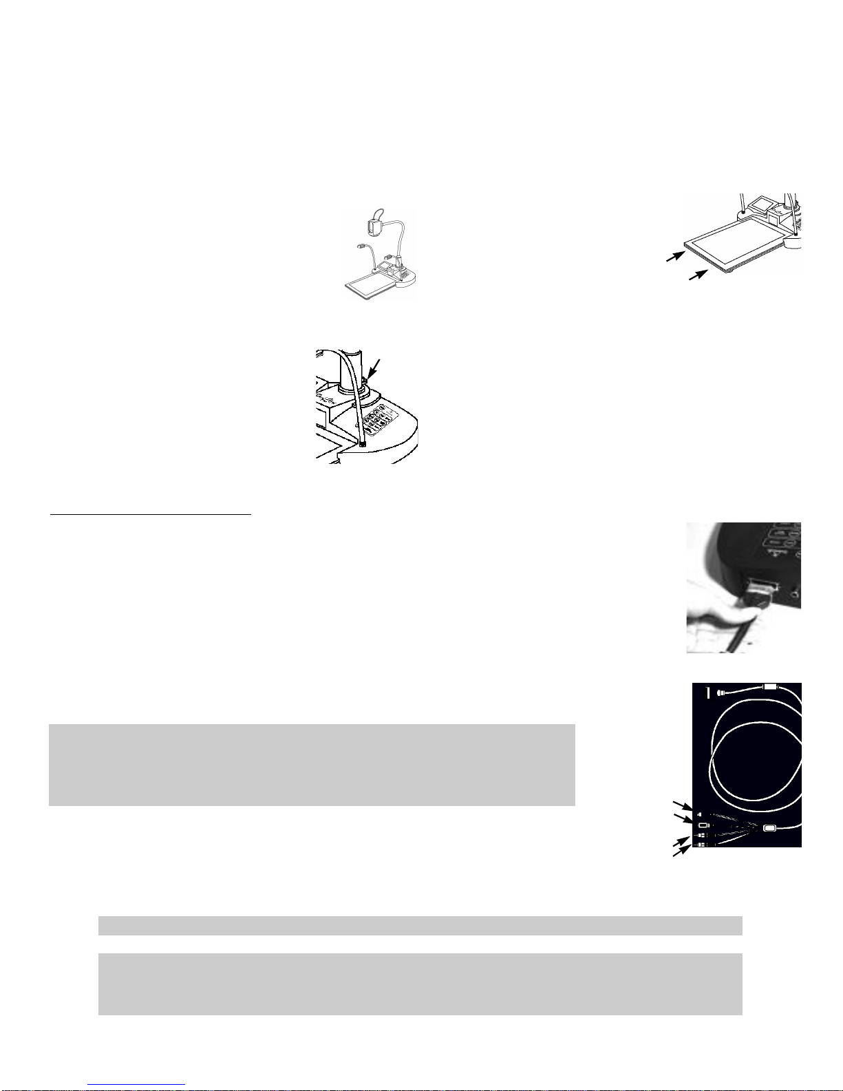
Setup and Operation Of The ProfCam
1. Set the camera unit on a flat,
solid surface.
4. Remove the light base from
its protective cover and slide it
as shown into the front of the
2. Grasp the camera module,
camera base
and raise the neck to its upright
position. When it is completely
vertical, slide the locking coupler
5. Remove the lens cover from
the head of the camera.
until it meets the base, locking
the neck in position.
thumb screw
6. Follow the instructions
below for information on how
3. Turn the thumb screw
clockwise until tight. T h i s
will further help to keep the
to connect the camera to a TV
or other monitor to view the
picture.
camera head steady.
Connecting The Main Cable
The main cable connects to the modular jack on the rear of the camera's base.
The cable will only connect one way and should snap in easily. If necessary,
turn the plug around and try inserting it again. Push the cable into the jack
until it snaps into place.
To remove the cable, press inward on the 'ears' of the connector, located on
each side of the plug and rock the connector gently from side-to-side while
pulling straight out from the camera base.
The other end of the main cable splits into four connectors:
Red RCA Audio; will connect to the audio-in jack of a TV
Yellow RCA Composite video; connects to the video-in jack of a TV
Black 4-pin S-Video; will connect to the video-in jack of S-Video capable TV's
Black Barrel Plug Power Connector; use with provided power supply to a wall outlet
In general, you will get a higher quality picture using the S-Video output.
However, many devices such as VCR's and TV's, are not capable of receiving
a S-Video signal. If your TV or VCR is not capable of receiving a S-video
signal, use the composite video jack on the camera's main cable.
THE AUDIO CONNECTION IS NOT REQUIRED TO VIEW A PICTURE FROM A PROFCAM
NOTE THAT THE S-VIDEO AND THE COMPOSITE VIDEO CONNECTORS ON THE PROFCAM ARE BOTH
ALWAYS LIVE. IT IS POSSIBLE TO CONNECT THE CAMERA TO TWO SEPARATE VIEWING SOURCES
(IE. A COMPUTER AND TV, OR TWO TV’S) AT THE SAME TIME.
S-video
power
audio
composite
Page 3
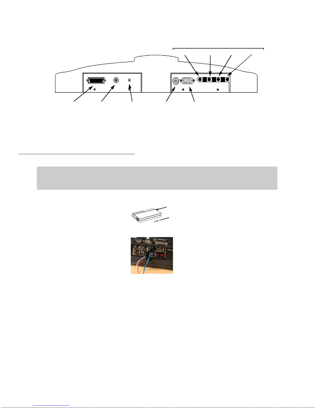
Connection Ports for ProfCam
LCD Screen Controls
Brightness Contrast Color Backlight
Main cable
connector
Video Passthrough
External
mic
Connecting The ProfCam To A TV Or VCR
THIS SECTION DOES NOT COVER REMOTE OPERATION USING THE CAMERA’S SERIAL PORT INTERFACE.
FOR MORE INFORMATION ON HOW TO CONFIGURE AND OPERATE THE CAMERA REMOTELY, REFER TO
THE “VIDEOLABS PROFCAM REMOTE OPERATIONS” MANUAL.
1. Plug the supplied power
adapter into a wall outlet and
connect the other end into the
black barrel jack on the main
camera cable.
2. Locate the video-in jacks
located on your T V or V C R .
Some units have these jacks
located on the front for convenience. If not, they will be in
the back.
3. Connect the S-Video jack
from the main cable to the
video-in jack on your TV/VCR.
If the TV/VCR is not S-Video
capable, use the composite
(RCA) video jack on the main
cable.
4. If desired, connect the audio
jack to the "audio in" jack on
the back of the TV/VCR.
External
synch
Serial Port
If your TV/ VCR has stereo
audio capabilities, connect the
audio jack to the right audio in
(normally the red jack).
5. If using a VCR, set the TV to
the channel normally used to
view VHS video tapes. Turn
the VCR to the auxiliary channel, or "line in". The VCR
power must be turned on.
6. If connecting directly to a
T V set, turn the channel to
a u x i l i a r y or "line in". T h e
p i c t u r e should appear on the
screen.
7. If you do not get a picture,
consult the manual for your TV
or VCR. Most of the time there
is a simple adjustment that
needs to be made that is
explained in the unit's manual.
Page 4

Connecting The ProfCam To A Computer (PC)
1. To be able to use the ProfCam
with a PC, the computer must
have a capture device installed
such as the StingerPro® and in
working condition.
2. Once you have a video capture
device installed, connect the SVideo jack from the main cable
to the video-in jack on the capture
device. If necessary, use the
composite (RCA) video jack on
the main cable.
3. Once you have a video capture
device installed, connect the SVideo jack from main cable to
the video-in jack.
If the capture device does not
have an S-Video jack, use the
composite (RCA) video jack on
the main cable.
4. Make sure the power adapter
is plugged into a wall outlet,
and that it is connected to the
black barrel-type jack on the
main camera cable.
5. Turn the camera power on,
then follow the instructions
provided with the capture
device on how to capture still
images or motion video.
Connecting The ProfCam To A Macintosh Computer
1. To be able to use the
ProfCam with a Macintosh
computer, the unit must be AVready; meaning it already has a
capture card installed inside the
computer. If you do not know
if your Macintosh is AV -ready,
contact your nearest Macintosh
dealer for assistance.
2. Connect the S-Video jack
from the camera's main cable to
the video-in jack on the back of
the computer. If the computer
is not S-Video capable, use the
composite RCA jack on the
main cable.
Remote Control
3. Plug the supplied power
adapter into a wall outlet, and
connect the other end to the
black barrel-type jack on the
main camera cable.
4. View the picture using Apple
Video Player or other similar
software. You may need to
change the settings for "video
source" before you can see a
picture.
The remote control for the ProfCam requires 4 'AAA' batteries (not included). Pull up the battery cover tab as
indicated to remove the back cover. Insert 4 'AAA' batteries, making sure the battery +/- terminal symbols line
up with the +/- symbols on the inside of the battery compartment.
IF THE REMOTE CONTROL WILL NOT BE USED FOR AN EXTENDED PERIOD OF TIME, REMOVE THE BATTERIES
AND STORE SEPARATELY. BATTERIES MAY LEAK AND DAMAGE THE REMOTE CONTROL UNIT.
Page 5

Turning The Camera On
Once the proper connections have been made, remove the lens cover from the
camera module. Press the power button on the camera keypad or remote control.
Allow a few seconds for the camera to warm up and set itself
accurately. If the picture is not seen, or is not properly in focus, refer to the
"Troubleshooting" section of this manual.
LCD Viewing Screen
For convenience, the ProfCam has a LCD monitor mounted permanently in the base of the camera. This will
allow the presenter to see exactly what is being shown on the screen without turning from the audience. If the
picture is not seen accurately on the LCD screen, try adjusting the controls on the back panel of the ProfCam for
optimal viewing. Note that viewing the LCD screen too far from the side may result in unnatural colors and/or
skewed images.
Using The Functions And Features Of Your ProfCam
Zoom
Lights
The ProfCam includes two halogen 'top' lights and a lightbase for enhanced
viewing of documents or other objects. To turn the lights on, press the
corresponding button - 'Top' to turn on the halogen top lights, or 'Lwr' to turn
on the light base.
Flex Lights
In the case that either of the halogen flex lights should ever burn out, they are easily replaceable. Unsnap the
metal heat shield from around the bulb, then twist the bulb a half-turn counter clockwise. This type of halogen
bulb can be purchased at most electronic stores or directly from VideoLabs, Inc.
brightness contrast color backlight
The ProfCam is capable of
zooming to a 14x magnification
factor. This will allow you to
quickly and easily show parts
of an object or document that
require close-up viewing.
1. Press and hold the corre-
sponding 'zoom' indicator button
on the keypad to zoom in or
out.
2. Release the button when the
zoom is at the desired level.
The camera will focus automat-
i c a l l y when the zoom motion
stops.
Page 6

HALOGEN LIGHTS GET VERY HOT DURING OPERATION.
WAIT FOR BULBS TO COOL BEFORE ATTEMPTING TO
REPLACE THEM.
Light Base
The ProfCam light base will not reach full luminescence until it has been powered up for at least 90 seconds. It
is a carefully designed piece of delicate electronics and there are no user-serviceable parts inside. Do not attempt
to change the bulbs in the light base! Doing so may expose you and others in the area to harmful chemicals.
The light base is rated for over 10,000 hours of operation and should not need replacement for the life of the
camera.
White Balance
The white balance of a camera is the function that determines what color is "true white". For example, under
some lighting conditions a white piece of paper may appear to have an undesirable yellow or blue tint. In these
cases you may wish to override the camera's automatic settings and set the white balance manually.
SOME OBJECTS MAY APPEAR TINTED INCORRECTLY IF THE WHITE BALANCE IS SET MANUALLY. IF THIS
OCCURS, RESET THE WHITE BALANCE TO ‘AUTO.’
The ProfCam's default white balance setting is automatic. If for any reason you
want this changed, press the 'manual' button on the keypad or remote control.
The camera will then 'snap to' the correct settings for what it is viewing at that moment. It will stay at this setting
even if the camera is powered down and turned back on. To return to the "auto" setting, press the auto button.
External Video Pass Through
The video pass through button switches between displaying the output from the ProfCam and the output from
another camera connected to the ProfCam. More information on viewing an external source is available in the
‘Using the Optional Ports’ section of the manual.
Document Viewing
The ProfCam's camera module can be easily rotated to adapt for different modes
of operation. When viewing a document on the light base, it is convenient to have
the document facing the presenter, as well as appear right-side up for the audience.
To rotate the camera for this type of operation, pull the spring pin on the camera
m o d u l e while sliding the module backwards. Remove the module completely from
the brackets, then rotate it 180º and reinsert.
spring pin
Remote Control
Operation of the remote control is the same as using the camera's keypad, with one exception - the ability to use
manual focusing rather than just the default auto-focus.
Page 7

Focus
External mic
For most general usage of the
ProfCam, the auto-focus setting
will suffice. However, for
focusing on close-up objects or
in other custom situations, you
may want to focus the camera
manually.
Using The Optional Ports On Your ProfCam
External Video Pass Through
1. Press and hold the corre-
sponding indicator button to
focus in or out.
2. Release the button when the
object is in focus.
3. To return the camera to auto
focus, press the 'auto' button on
the remote control.
The ProfCam has a built in feature
that allows another video
source to be displayed quickly
and easily without having to
disconnect the ProfCam. This
allows you to use smaller cameras
1. Connect the composite video
output from another source
(such as a camcorder or
VideoLabs’ ScholasticCam) to
the Video Pass-through jack on
the ProfCam.
Video Pass-through
to enhance your presentation
without having to disconnect the
ProfCam or connect new wires
with the alternate camera.
2. Press the Video Pass-through
button on either the remote
control or the keypad.
The video from the external source can then be viewed on both the LCD screen in the base of the ProfCam and
through the composite video output of the ProfCam. Note that the S-video jack will still be video output from
the ProfCam
External Microphone Input
If the built-in microphone in the base of the ProfCam is insufficient for your
audio needs, connect an external microphone into the mic-in jack on the rear
of the camera. This microphone will then operate identically to the internal
microphone in the camera. When an external microphone is connected,
the ProfCam's internal microphone is automatically turned off .
RS232 Serial Port Interface
Remote operation of the ProfCam is possible via a RS232 serial port.
This type of operation offers more features and options to customize your ProfCam.
For operation of the camera from a computer (PC) console, connect the supplied
serial cable between the serial port on the camera and a serial port on the computer.
Detailed information on how to configure and operate the camera remotely is
available in the "VideoLabs ProfCam Remote Operation" manual.
serial port
Page 8

External Sync
For times when the ProfCam is connected with other cameras to the same monitor, it may be convenient to take
advantage of the sync option on the ProfCam. This works best when there are two or more cameras connected
to the same video monitor, and you are continually switching between sources (i.e. between the ProfCam and
other cameras). Normally when the source is changed, the picture will flicker or run for a second or two before
being seen properly. Connecting the cameras together via the external synch port and a synch generator will
eliminate that flicker.
Packing The Camera For Storage Or Transportation
The carrying case provided with the ProfCam has been designed for maximum protection of the camera while
minimizing space and awkwardness for transportation. It is extremely important that the camera be packed properly
to avoid damaging both the electronics and the casing of the camera.
Care and Cleaning
• Do not attempt to take the camera apart. There are no user-serviceable components inside.
• Do not spill liquids onto the camera.
• Avoid touching the lens. For smears or smudges, clear any dust with a blower and wipe stains with a glass
cleaner and clean cloth.
• Do not use glass cleaner to clean the LCD screen! Any ammonia-based products will turn the glass cover
foggy and result in unsatisfactory images. For best results, use a damp cloth or paper towel.
• To clean exterior of camera, wipe with a clean damp cloth. Do not use any abrasive chemicals.
• Use both hands whenever adjusting the flexible neck on the camera. This will avoid any unnecessary strain
on the base of the camera and will help keep the camera from tipping over unexpectedly.
Operating And Storage Conditions
Do not store or operate the ProfCam under the following conditions:
• Above 40ºC (104ºF) or below 0ºC (32ºF)
• High humidity environments
• Dusty environments
• In inclement weather
• Under severe vibration
• In direct sunlight or other bright lights
1. Loosen the thumbscrew at
the base of the camera neck by
turning it counter-clockwise.
2. Collapse the neck by lifting
up the locking sleeve, then
wrap the neck around the base
of the camera.
3. Curve each of the flexible
'top' lights so they are in place
over the top of the camera
neck.
4. Slide the camera into the
main compartment in the carry
case with the jacks in the rear
of the base facing down.
5. Place the light base back into
its protective sleeve. T h e n
slide the light base into the narrow compartment along the
side of the carry case.
6. Wrap all cables, and place in
the remaining compartment.
Page 9

Troubleshooting
Problem
Green LED does not indicate camera
power is turned on.
Green LED is on, but no picture appears
on the screen.
Audio is weak, and/or excessive feedback
is heard.
Suggestion
Make sure the Power Adapter is plugged into a wall outlet and the
main video cable of the camera.
Check all cable connections to verify they are tight and fully
inserted.
Verify the lens cover has been removed.
Is the person speaking too far from the base of the camera or at
the rear of the base?
The camera mic should ideally be positioned behind the speakers
being used. This will help eliminate feedback.
Verify the audio out cable from the camera is plugged into a line-in
jack. If a mic-in jack is used, you will experience more feedback
and other noise.
Camera will not focus automatically.
Images on the LCD screen appear
distorted, and/or colors are inaccurate.
Make sure the camera is not in manual focus mode by pressing
the 'auto' button on the remote control.
When using maximum zoom capabilities, it is necessary to use
manual focus when viewing objects closer to the lens than 3 feet.
Use the control knobs on the rear of the base to adjust the LCD as
desired.
LCD screens have a limited range of visibility. Attempting to view
the picture too far from the side may result in an unsatisfactory
i m a g e .
 Loading...