

Page 1
PAN6400 Installation Guide
Addendum
Panorama PANVP700 Video Port
The PANVP700 Video Port provides a way of connecting to a video display from a source connected to the Panorama
PAN6400 Video Distribution Center (VDC) The PANVP700 also features an IR receiver input and ships with an IR receiver.
If you have the source remote, you can control the source from any room that has a PANVP700 connected to that source. The
PANVP700 is designed for installations using the PAN6400 as a standalone device or a PAN6400 that is controlled by a third-
party controller using RS-232.
NOTE: The PAN6400 IR receiver is disabled if the PAN6400 is connected to a Musica™ system. Musica keypads already
provide this functionality.
NOTE: Use standard, unshielded CAT5e cable for wiring between the PAN6400 and the PANVP700 and terminate it using
the 568a standard.
The PANVP700 ships with:
a NetStreams IR receiver,
wall plate,
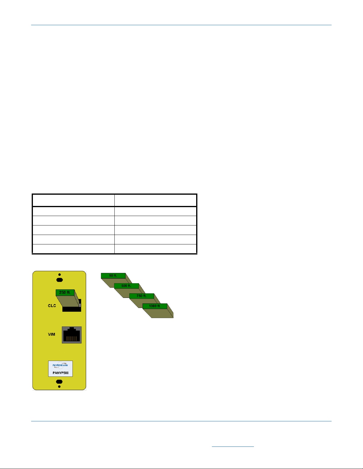
five Cable Length Compensation (CLC) cards (in 50-, 250-, 500-, 750-, and 1000-ft increments).
NOTE: The PANVP700 comes with the 250-ft CLC card already inserted into the CLC slot on the back panel.
Panels
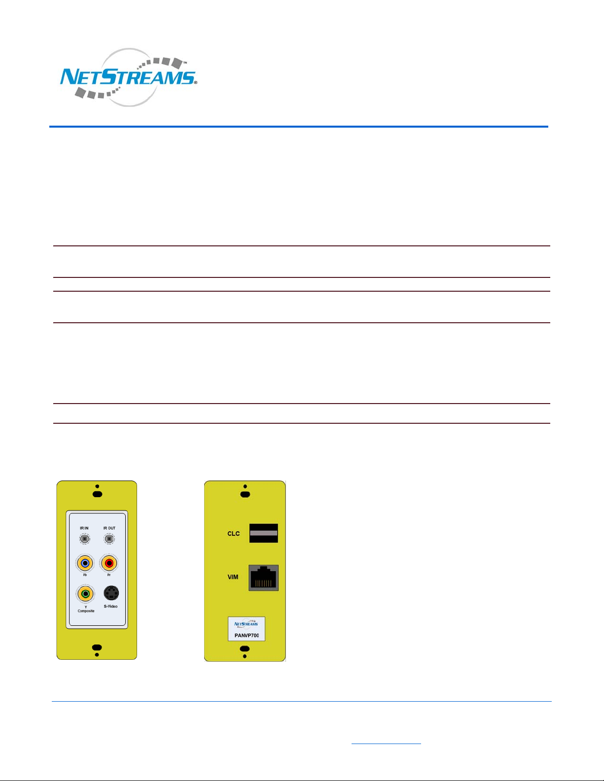
Figure 1 shows the front and back panels of a PANVP700.
Front Panel
Front Panel
Figure 1 PANVP700 front and back panels.
Back Panel
NS-0106-7149, Addendum 1
All specifications subject to change without notification. All rights reserved. Copyright © 2006 NetStreams
Main +1 512.977-9393 / fax +1 512.977.9398 / Toll Free Technical Support +1 866-353-3496
3600 W. Parmer Lane, Suite 100; Austin, TX 78727 / www.netstreams.com.
Page 2
PANVP700 Addendum
Front Panel
The front of the PANVP700 supports the following interfaces:
IR In - Connects to a PAN6400 IR receiver.
IR Out - Connects an IR emitter to the video source.
Pb/Pr - Connects to component display devi ces.
Y/Composite - Lets you connect composite or compon ent display devices and digital audio to the PAN6 400 using a
yellow or green RCA connector.
S-Video lets you connect S-Video to a display.
Rear Panel
The back panel of the PANVP700 includes:
CLC - this is an expansion slot for maximizing signal processing based on the distance the cable runs from the PAN VP700
to the PAN6400. The operation is handled by inserting the CLC card closest to the length of cable you are running (see
Table 2). CLC cards come in 50 ft, 250 ft, 500 ft, 750 ft, and 1000 ft allotments (included with your PANV P700). The
250-ft CLC card is pre-inserted for your convenience.
Table 1
CLC Usage
CLC Card Covers a Cable Length of
50 1 to 50 feet
250 51 to 250 feet
500 251 to 500 feet
750 501 to 750 feet
1000 751 to 1000 feet
See Figure 2 for an example of how to insert a CLC card into the PANVP700.
Figure 2 CLC card (insertion)
2 NS-0106-7149, Addendum
All specifications subject to change without notification. All rights reserved. Copyright © 2006 NetStreams
Main +1 512.977-9393 / fax +1 512.977.9398 / Toll Free Technical Support +1 866-353-3496
3600 W. Parmer Lane, Suite 100; Austin, TX 78727 / www.netstreams.com.
Page 3

Addendum PANVP700
Video Interface Module (VIM) port - uses RJ-45 connections to connect the PANVP700 with the room outputs on the
PAN6400.
Connecting IR
Figure 3 shows how to connect IR to and from the PANVP700. To connect IR, complete the following steps:
1. Connect the 3.5 mm phono jack of the NetStreams IR receiver (included) to the IR IN port of the PANVP700.
2. Place the NetStreams IR receiver in a location where it can receive the IR signal from the source remote.
NOTE: When placing the NetStreams IR receiver, choose a location that is shaded from fluorescent light. The NetStreams IR
receiver works best if the dome is placed so that the dome faces the IR remote.
3. Connect IR emitter to the IR window on the front of the display.
4. Connect the 3.5 mm phono jack to the IR OUT port of the PAN VP700.
Figure 3 Connecting PAN6400 IR receiver and emitter
Learning Source IR to the PAN6400
IR codes are divided into two states when a PANVP700 is connected:
Room IR
Source IR
NOTE: When using third party systems to control the PAN6400, you may need to store the source IR into the PAN6400.
NOTE: Always stand within 18 inches of the receiver on the PAN6400 when programming IR. Stay away from fluorescent
light or ambient sunlight as both will affect data transmission.
There is a time out after thirty seconds to perform each task.
1. Tur n the PA N6400 on.
2. Standing within 18 inches of the IR window on the PAN6400, point the PAN6400 remote control at the window.
NS-0106-7149, Addendum 3
All specifications subject to change without notification. All rights reserved. Copyright © 2006 NetStreams
Main +1 512.977-9393 / fax +1 512.977.9398 / Toll Free Technical Support +1 866-353-3496
3600 W. Parmer Lane, Suite 100; Austin, TX 78727 / www.netstreams.com.
Page 4

PANVP700 Addendum
3. Press and hold the Menu button on the PAN6400 remote for two seconds.
Lights on the PAN6400 will flash on and off. This means you’ve entered Learning mode.
4. Press the down arrow.
The LED turns from green to red. The first red light under “Source” indicates you are on the first step of IR Learning.
5. Use the left and right arrow keys on the remote to select the source you want to program.
When the LED on the front of the PAN6400 is on for that source, that source is being programmed.
6. Press the command (such as “Play”) you want to program on the PAN6400 remote.
The second red light under “Source” activates. This indicates you have completed the second step of IR Learning.
NOTE: The LEDs on the PAN6400 that are labeled “Display” are used for the sources.
When learning source IR, the Display LEDs on the PAN6400 indicate the source being learned. For example, if the
LED for Room 1 is lit, Source 1 is being programmed. Room 2 is Source 2, and so on. Since only four sources are
available for programming, the Room 5 and 6 LEDs are reserved for special functions.
7. From the remote for the source, press the button to be learned into the PAN6 400.
8. Press the button again on the source remote.
If IR is learned, the room and source LEDs will once again light in and out.
If IR is not learned, the source LEDs flash rapidly.
9. To exit Programming mode, press the Menu button.
4 NS-0106-7149, Addendum
All specifications subject to change without notification. All rights reserved. Copyright © 2006 NetStreams
Main +1 512.977-9393 / fax +1 512.977.9398 / Toll Free Technical Support +1 866-353-3496
3600 W. Parmer Lane, Suite 100; Austin, TX 78727 / www.netstreams.com.
 Loading...