

Page 1
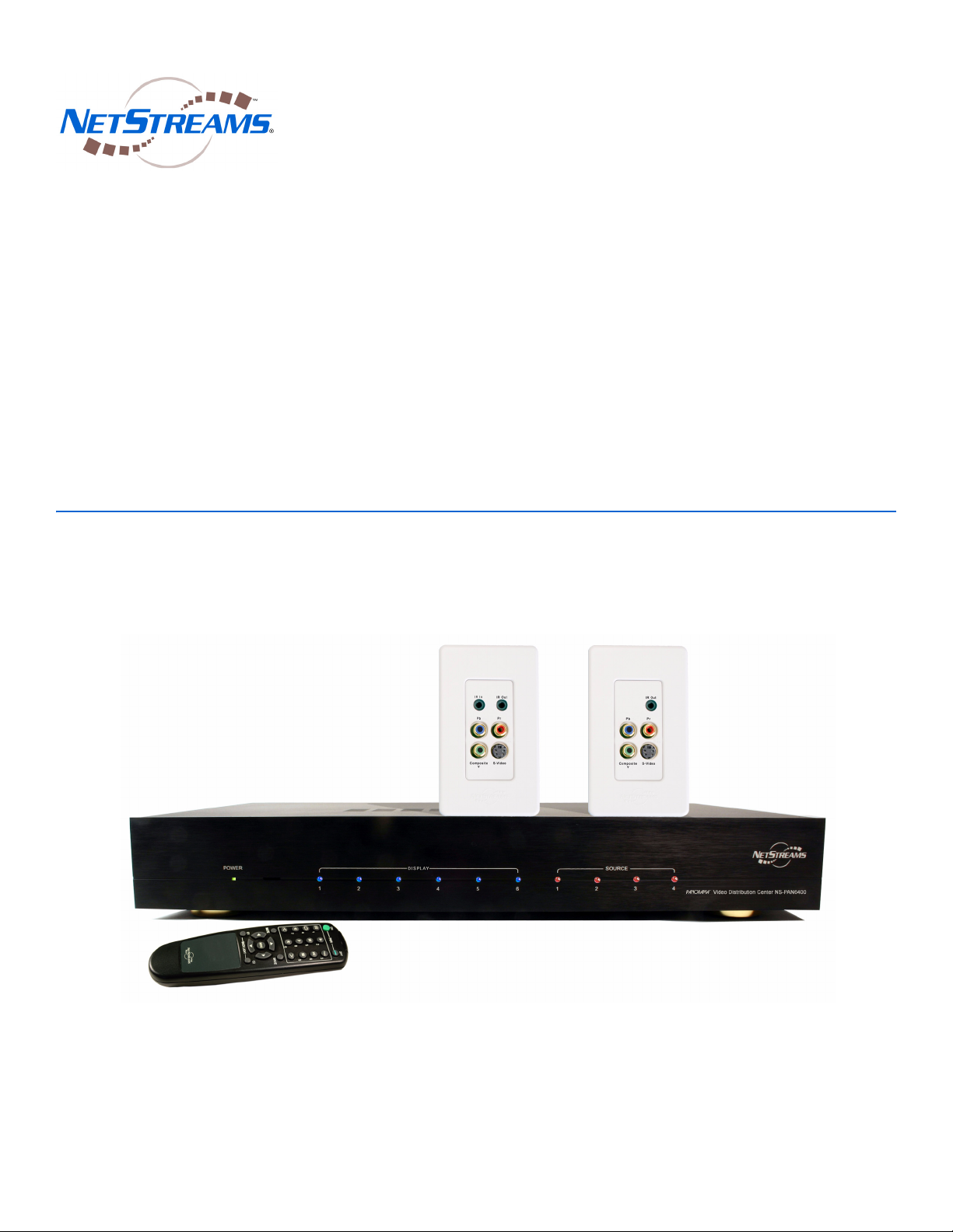
PANORAMA™ PAN6400
Multi-Room Video & Control
System
Installation Guide
Page 2

Title: PAN6400 Installation Guide
Document Number: 020001A
Original Publication Date: January 1, 2006
Revised Publication Date: November 3, 2006
All rights reserved.
Copyright © 2006 by NetStreams.
All brand names, product names, and trademarks are properties of their
respective owners.
Copyright
3600 W. Parmer Lane, Suite 100
Austin, TX 78727
USA
Phone: +1 512.977.9393
Fax: +1 512.977.9398
Toll Free Technical Support 1-866-353-3496
Page 3

Contents
Chapter 1: Introduction ................................................................................................................1-1
Features ...................................................................................................................................... 1-2
Package Contents ...................................................................................................................... 1-2
Required Tools .......................................................................................................................... 1-2
NetStreams Documentation ...................................................................................................... 1-3
Contacting NetStreams ............................................................................................................. 1-3
Safety Requirements ................................................................................................................. 1-3
Hardware Labels ................................................................................................................... 1-3
Safety Instructions ................................................................................................................ 1-4
Qualified Service Personnel .................................................................................................. 1-5
Chapter 2: System Overview ....................................................................................................... 2-1
Configuration ............................................................................................................................ 2-1
Standalone ............................................................................................................................. 2-1
Integrated with the Musica ................................................................................................... 2-1
Integrated with DigiLinX or Third-Party Control Systems .................................................. 2-2
System Components .................................................................................................................. 2-2
PAN6400 VDC ..................................................................................................................... 2-3
Remote Control ..................................................................................................................... 2-4
Panorama Video Ports: PANVP500 and PANVP700 ......................................................... 2-5
Chapter 3: Configuring Standalone Installations ......................................................................3-1
Configuring a Single PAN6400 VDC ...................................................................................... 3-1
Component Video ................................................................................................................. 3-2
S-Video with Coaxial Digital (S/PDIF) Audio ..................................................................... 3-4
Composite Video with Coaxial Digital (S/PDIF) Audio ...................................................... 3-6
Adding Additional Displays (Cascade Mode) ........................................................................ 3-7
Chapter 4: Integrating with NetStreams Musica 5000 Series ...................................................4-1
Integrating a Single Musica MU5066ADC and PAN6400 VDC ........................................... 4-1
Adding Additional Input Ports (Mirrored Mode) ................................................................. 4-3
Adding Additional Displays (Cascade Mode) ........................................................................ 4-6
Integrating the Musica MUR2EM Network Interface .......................................................... 4-7
Chapter 5: Integrating Panorama
Integrating a Single DigiLinX System and PAN6400 VDC .................................................. 5-1
Adding Additional Input Ports (Mirrored Mode) ................................................................. 5-4
Adding Additional Displays (Cascade Mode) ........................................................................ 5-7
with DigiLinX ........................................................................ 5-1
iii
Page 4

NetStreams Pan6400 Installation Guide
Chapter 6: Using IR ....................................................................................................................... 6-1
IR Overview ............................................................................................................................... 6-1
Remotes ................................................................................................................................ 6-2
Panorama remote .......................................................................................................... 6-2
Source/Display Remote or Universal Remote ............................................................... 6-3
PAN6400 VDC IR Storage and Access ................................................................................ 6-4
PAN6400 VDC LED Meaning ............................................................................................. 6-4
Learning IR ............................................................................................................................... 6-5
Standalone Installations ........................................................................................................... 6-7
Testing IR Integration ........................................................................................................... 6-7
Cascade Mode ....................................................................................................................... 6-7
Integrating with Musica ........................................................................................................... 6-8
Storing IR codes .................................................................................................................... 6-8
Testing IR Integration ........................................................................................................... 6-8
Learning IR in Mirrored Mode ............................................................................................. 6-9
Learning IR in Cascade Mode .............................................................................................. 6-9
Integrating with DigiLinX ........................................................................................................ 6-9
Testing IR Integration .........................................................................................................6-10
Learning IR in Mirrored Mode ........................................................................................... 6-10
Learning IR in Cascade Mode ............................................................................................ 6-10
Chapter 7: Troubleshooting ......................................................................................................... 7-1
iv
Page 5

Chapter
1
Introduction
Congratulations on the purchase of your new Panorama™ PAN6400 Video
Distribution & Control system. Offering a new breed of video products, the
NetStreams® Panorama system combines video distribution and switching with
infrared (IR) control of displays and sources, instead of requiring a dedicated control
system. The NetStreams Panorama system’s value and performance is unmatched in
today’s market: delivering phenomenal video clarity and source content of up to
1080p (high definition resolution).
With Panorama’s “cable length compensation” (CLC) technology you can distribute
high definition video sources up to 1,000 feet per room from the headend. Now your
HDTV, Blu-ray, or HD-DVD experience can be shared around the residential or
commercial project with no discernible video quality degradation. Panorama was
designed for installers and customers who demand great quality, an affordable price,
and ease of installation.
The Panorama PAN6400 Video Distribution Center (VDC) distributes four sources to
six rooms (expandable to 18). The system selects any available video source and
distributes it to any of the rooms selected. Users can simultaneously access and control
any of the four different sources from separate rooms. Compensating automatic gain
adjustments at the inputs ensure that the sources are distributed at equal levels.
™
The PAN6400 VDC offers plug and play integration with NetStreams Musica
MU5066 Multi-Room Audio system and also works with the NetStreams DigiLinX™
IP-Based Multi-Room Audio and Control system to provide the video solution for
your project. With the PAN6400 VDC, you can distribute component, S-Video, or
composite video signals and/or coaxial digital S/PDIF digital audio signals to as many
as six rooms per PAN6400 VDC.
Up to three PAN6400 VDCs can be cascaded to achieve a total of 18 zones of high
definition video and audio when integrated with Musica. When used with DigiLinX or
a third-party system, there is no limit to the number of Panorama VDCs that can be
used in a system.
PAN6400 VDCs can also be mirrored to double the number of connections from three
(with one VDC) to six (with two VDCs), allowing the distribution of component video
and S/PDIF digital audio simultaneously. In this case Panorama distributes both video
and audio and Musica or DigiLinX controls the PAN6400 VDCs.
All specifications subject to change without notification. All rights reserved. Copyright © 2006 NetStreams
Main +1 512.977-9393 / fax +1 512.977.9398 / Toll Free Technical Support +1 866-353-3496
3600 W. Parmer Lane, Suite 100; Austin, TX 78727 / www.netstreams.com.
1-1
Page 6

NetStreams Panorama System Installation Guide
NOTE
Many other exciting combinations for unique installations exist. For more information
on some of these applications, please see the Panorama Application Notes in the
dealer section of the NetStreams website (www.netstreams.com).
Features
The PAN6400 VDC features include:
display outputs - supports six displays (expandable to 18)
source inputs - supports four sources
IR inputs and outputs - supports IR for four sources and provides a common input
and output
IR learning and storage - controls up to four sources and six displays per VDC
RS-232 ports - supports connection to Musica, DigiLinX, or other third-party
control systems
hand-held remote control.
Package Contents
The PAN6400 VDC
requires 2U of rack
space. To mount the
PAN6400 VDC, use the
supplied non-standard
rack mount ears or
purchase a Middle
Atlantic
(www.middleatlantic.com)
shelf (part number
RSH4A2S) for
mounting into a
standard 19-inch rack.
Required Tools
The NetStreams Panorama system consists of the PAN6400 VDC and the Panorama
Video Ports (sold separately). Your PAN6400 VDC comes with the following:
PAN6400 VDC (video distribution center)
12v DC power supply
five S-Video to RCA adapters
four 3.5 mm male to 3.5 mm male IR extension cables
one remote control
one RS-232 null modem cable
installation guide
one set non-standard rack mount ears.
Tools required for installation of a PAN6400 VDC include:
small flathead screwdriver
CAT5 tester
volt meter
RJ45 crimping tool
RJ45 connectors
1-2
All specifications subject to change without notification. All rights reserved. Copyright © 2006 NetStreams
Main +1 512.977-9393 / fax +1 512.977.9398 / Toll Free Technical Support +1 866-353-3496
3600 W. Parmer Lane, Suite 100; Austin, TX 78727 / www.netstreams.com.
Page 7

wire cutters
wire strippers.
NetStreams Documentation
To view or print NetStreams documentation:
1. From a web browser, go to www.netstreams.com.
2. Click the Dealer Login button.
3. Log in with your dealer user name and password.
4. Select Dealer Documents.
Contacting NetStreams
If you have technical questions about the PAN6400 VDC that are not covered in this
manual:
visit the dealer section of the NetStreams website (www.netstreams.com) for
application notes
Introduction
email support@netstreams.com
call 1-866-353-3496 or 1-512-977-9393.
Safety Requirements
Safe installation and use of NetStreams products requires a thorough knowledge of the
products and proper installation practices. Therefore, please read this manual before
beginning and heed all warnings. Follow all instructions provided and retain them.
Adhere to all warnings on the product and in the instructions.
Hardware Labels
CAUTION! TO REDUCE THE RISK OF FIRE OR ELECTRIC SHOCK, DO NOT EXPOSE THIS
APPLIANCE TO RAIN OR MOISTURE. TO REDUCE THE RISK OF ELECTRIC SHOCK, DO
NOT REMOVE COVER. NO USER - SERVICEABLE PARTS INSIDE. REFER SERVICING TO
QUALIFIED SERVICE PERSONNEL.
. The lightning flash with arrowhead symbol, within an equilateral triangle, is intended
to alert the user to the presence of un-insulated “dangerous voltage” within the
products enclosure that may be of sufficient magnitude to constitute a risk of electric
shock to persons.
The exclamation point within an equilateral triangle is intended to alert the user to the
presence of important operating and maintenance (servicing) instructions in the
literature accompanying the appliance.
All specifications subject to change without notification. All rights reserved. Copyright © 2006 NetStreams
Main +1 512.977-9393 / fax +1 512.977.9398 / Toll Free Technical Support +1 866-353-3496
3600 W. Parmer Lane, Suite 100; Austin, TX 78727 / www.netstreams.com.
1-3
Page 8

NetStreams Panorama System Installation Guide
WARNING
NOTE
Safety Instructions
CAUTION! To reduce the risk of possible fire or electrical shock, make all connections and finish all terminations
before turning on power to the unit.
Do not block any ventilation openings. For example; do not place on a rug, bed,
sofa, or similar surface which impedes airflow across the chassis. Airflow through
the ventilation openings should be unobstructed. Provide ventilation on all sides of
the appliance, especially if placed in a rack. If ventilation is blocked, the appliance
may overheat and malfunction.
Do not install near heat sources such as radiators, heat registers, stoves, or other
appliances (including amplifiers) that produce heat. Do not expose the appliance to
direct sun light as the appliance’s internal components temperature may rise and
shorten the life of the components. Avoid damp and dusty places.
Before turning the
power on for the first
time, read this section
carefully. All models are
designed for use only
with the power supply
voltage of the region
where they are sold.
NetStreams provides a
VSPW 12v DC power
supply. Review whether
this is the appropriate
voltage and power
supply for your country
and call NetStreams
Technical Services at
(866) 353-3496 if you
have any questions.
Unplug this apparatus during lightning storms or when unused for long periods of
time.
Only connect the appliance to a power supply described in the operating
instructions or as marked on the appliance.
Do not defeat the safety purpose of the polarized or grounding-type plug. A
polarized plug has two blades with one wider than the other. A grounding type plug
has two blades and a third grounding prong. The wide blade or the third prong is
provided for your safety. If the provided plug does not fit into your outlet, consult
an electrician for replacement of the obsolete outlet.
A label located at the rear panel power connection indicates the DC power input for
the unit. The label will read 100-240V DC 12V/1.5A Adapter.
Route power cord and other cables so that they are not likely to be walked on,
tripped over, pinched, or stressed. Pay particular attention to condition of cords and
cables at plugs, and the point where they exit from the apparatus. To prevent risk of
fire or injury, damaged cords and cables should be replaced immediately.
Only use attachments/accessories specified by the manufacturer.
The apparatus should be serviced by qualified service personnel when:
the power supply cord or the plug has been damaged
objects have fallen or liquid has spilled into the unit
the apparatus has been exposed to rain or other moisture
the apparatus does not appear to operate normally
the apparatus has been dropped, or the enclosure damaged.
Do not attempt to service the appliance beyond that described in the operating
instructions. All other servicing should be referred to qualified service personnel.
Clean only with a dry cloth. Do not use rough material, thinners, alcohol or other
chemical solvents or cloths since this may damage the finish or remove the panel
lettering. Never pour any liquid on or in the device.
1-4
All specifications subject to change without notification. All rights reserved. Copyright © 2006 NetStreams
Main +1 512.977-9393 / fax +1 512.977.9398 / Toll Free Technical Support +1 866-353-3496
3600 W. Parmer Lane, Suite 100; Austin, TX 78727 / www.netstreams.com.
Page 9

Do not use near water, for example, near a bathtub, washbowl, kitchen sink,
laundry tub, in a wet basement, near a swimming pool, etc.
Do not expose the appliance to dripping or splashing and do not place objects filled
with liquids, such as vases, on the appliance.
Do not touch the appliance with wet hands. Do not handle the appliance or the
power cord when your hands are wet or damp. If water or any other liquid enters
the appliance chassis, take the appliance to qualified service personnel for
inspection.
Only use the appliance with a cart or stand recommended by the manufacturer. An
appliance and cart combination should be moved with care. Quick stops, excessive
force and uneven surfaces may cause the appliance and cart combination to
overturn.
Only mount the appliance to a wall or ceiling as recommended by the
manufacturer.
Qualified Service Personnel
Only NetStreams employees are qualified to inspect or repair internal damage to
NetStreams equipment. If your NetStreams device is damaged, contact NetStreams
Technical Support for a Return Merchandise Authorization.
Introduction
All specifications subject to change without notification. All rights reserved. Copyright © 2006 NetStreams
Main +1 512.977-9393 / fax +1 512.977.9398 / Toll Free Technical Support +1 866-353-3496
3600 W. Parmer Lane, Suite 100; Austin, TX 78727 / www.netstreams.com.
1-5
Page 10

NetStreams Panorama System Installation Guide
1-6
All specifications subject to change without notification. All rights reserved. Copyright © 2006 NetStreams
Main +1 512.977-9393 / fax +1 512.977.9398 / Toll Free Technical Support +1 866-353-3496
3600 W. Parmer Lane, Suite 100; Austin, TX 78727 / www.netstreams.com.
Page 11

Configuration
You can install the PAN6400 VDC alone or in conjunction with Musica, DigiLinX, or
other control systems. In any of these configurations, you can also install multiple
PAN6400 VDCs to add additional zones or signals.
Standalone
You can use the Panorama as a standalone video distribution and control system.
Panorama can switch video and control both video sources and displays without a
third-party controller. The PAN6400 VDC can connect to video sources with
component, composite, or S-Video cables.
Chapter
2
System Overview
The displays are controlled either locally with the display’s remote control or from the
headend with learned IR commands stored in the PAN6400 VDC.
The sources are controlled by learned IR stored in the VDC. Panorama also offers IR
pass-through with the PANVP700 to control the source using the source’s remote
control.
Two or more PAN6400 VDCs can be connected in a cascade to increase the number of
rooms where the video and audio sources are distributed. Each VDC adds six more
zones, while the sources available for distribution remains at four. For an example of a
cascaded configuration, see Figure 3-6 on page 3-9
Integrated with the Musica
When Panorama is integrated with the NetStreams Musica 5000 Series Multi-Room
Audio & Control system, the two systems are virtually plug and play. Use the Musica
MU5066ADC to distribute analog audio and the PAN6400 VDC to distribute
balanced, line-level video.
The PANVP500 (VP500) Video Port connects as many as six displays to each
PAN6400 VDC. The AP450 or AP500 Audio Ports provide fixed or variable audio
output and/or local source input. The Musica keypads control all of the audio and
video functions as well as IR pass-through functions via the IR receiver window on the
front of the keypad.
.
All specifications subject to change without notification. All rights reserved. Copyright © 2006 NetStreams
Main +1 512.977-9393 / fax +1 512.977.9398 / Toll Free Technical Support +1 866-353-3496
3600 W. Parmer Lane, Suite 100; Austin, TX 78727 / www.netstreams.com.
2-1
Page 12

NetStreams Panorama System Installation Guide
When integrated with Musica, you can mirror multiple PAN6400 VDCs and have them
function as a single VDC to increase the number of connections. When mirroring two
PAN6400 VDCs, you increase the connections per source from three to six.
As with standalone configurations, you can cascade a configuration with PAN6400
VDC and Musica to add additional zones.
You can include a Musica MUR2EM Network Interface in the integrated installation.
This allows the system to be controlled from a web browser.
Integrated with DigiLinX or Third-Party Control Systems
The Panorama video distribution system also integrates with the NetStreams DigiLinX
IP-Based Multi-Room Audio and Control system or other control systems through
RS-232 connections.
The PAN6400 VDC distributes balanced, line-level video and controls displays.
DigiLinX controls the PAN6400 VDC switching functions through a ControLinX™
driver and distributes the video sources’ audio over the DigiLinX network using a
MediaLinX™ for each source. Each MediaLinX also serves as the controller for each
video source.
PAN6400 VDC can also distribute S/PDIF digital audio to audio-video (A/V)
receivers in tandem with MediaLinX distributing the audio over network when using
S-Video or composite video connections. Alternatively, you can mirror multiple
PAN6400 VDCs and have them function as a single VDC to increase the number of
connections. This allows you to distribute component video from one PAN6400 VDC
and coaxial digital (S/PDIF) audio from the other PAN6400 VDC.
You can cascade a configuration with PAN6400 VDC and DigiLinX integrated to add
additional zones. This requires a ControLinX for each Panorama.
The Panorama can send and receive RS-232 commands allowing third-party
controllers to use the Panorama as a video switcher. The same general wiring
procedure applies when integrating with third-party control systems as with DigiLinX.
The RS-232 port wiring in particular is the same.
A full RS-232 protocol guide is available to authorized dealers from the dealer section
of the NetStreams website (www.netstreams.com).
System Components
There are many ways to use Panorama, but the components of the system are finite.
The main components include:
2-2
PAN6400 VDC
PANVP500 or PANVP700 Video Ports
third-party video source (cable, satellite dish, or other input device)
third-party display (TV, Plasma/DLP/LCD or projectors).
All specifications subject to change without notification. All rights reserved. Copyright © 2006 NetStreams
Main +1 512.977-9393 / fax +1 512.977.9398 / Toll Free Technical Support +1 866-353-3496
3600 W. Parmer Lane, Suite 100; Austin, TX 78727 / www.netstreams.com.
Page 13
NOTE
Additional equipment may include:
Musica MU5066ADC (for Musica system integration)
AP300 or AP500 (for Musica system integration)
ControLinX (for DigiLinX system integration)
MediaLinX (for DigiLinX system integration)
MUR2EM (in conjunction with Musica MU5066ADC system integration).
PAN6400 VDC
System Overview
The PAN6400 VDC
requires 2U of rack
space. To mount the
PAN6400 VDC, use the
supplied non-standard
rack mount ears or
purchase a Middle
Atlantic
(www.middleatlantic.co
m) shelf (part number
RSH4A2S) for
mounting into a
standard 19-inch rack.
Familiarize yourself with the physical properties of the PAN6400 VDC to help plan for
your installation.
The physical dimensions of the PAN6400 VDC are:
16.95 inches (or 424 mm) wide
2.28 inches (or 57 mm) high
9.04 inches (or 226 mm) deep.
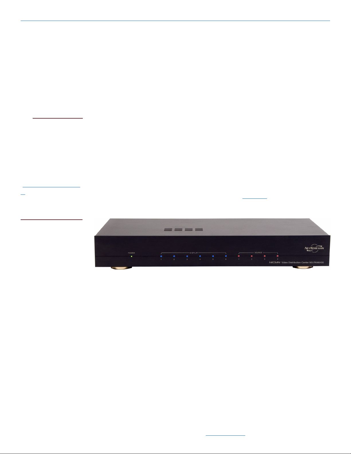
The front panel of the PAN6400 VDC has LEDs that indicate the state of the VDC
when in normal mode and assist with IR learning (see Using IR on page 6-1 for more
information). Figure 2-1 shows the front of the PAN6400 VDC.
Figure 2-1 PAN6400 VDC (front panel)
The front panel consists of the following LEDs:
one (green/red) power LED
an IR window (located next to the POWER LED)
six blue DISPLAY LEDs
four red SOURCE LEDs.
2-3
All specifications subject to change without notification. All rights reserved. Copyright © 2006 NetStreams
Main +1 512.977-9393 / fax +1 512.977.9398 / Toll Free Technical Support +1 866-353-3496
3600 W. Parmer Lane, Suite 100; Austin, TX 78727 / www.netstreams.com.
Page 14

NetStreams Panorama System Installation Guide
NOTE
NOTE
The display connected
to the MONITOR ports
shows what is playing
on the display and
source currently lit on
the PAN6400 VDC
LEDs. If Sources 3 and
4 are playing on
different displays, and
the Display 2 and
Source 4 LEDs are on,
the MONITOR display
shows Source 4.
Use a CAT5, 568aterminated cable for
Video Port connections.
For further information
on the VP500 or VP700,
see Panorama
Video
Ports: PANVP500 and
PANVP700 on page 2-5.
The rear panel of the PAN6400 VDC has ports and the power input. Figure 2-2 shows
the rear panel.
Figure 2-2 PAN6400 VDC (rear panel)
Available ports include:
six RCA-type input/output ports for each of four video sources labeled S1 - S4
three RCA-type output ports labeled MONITOR for connecting a monitor to the
PAN6400 VDC at the headend which displays last selected source and room
six RJ45 ports transmits the video signal to a VP500 or VP700 Video Port for use
with up to six displays
four IR input/output ports for each of four video sources labeled S1 - S4 and a
common input and output connection labeled C
two RS-232 ports (IO1 and IO2):
IO1 - connects to the Musica MU5066ADC
IO2 - connects to DigiLinX, another PAN6400 VDC (when integrated with
Musica), a computer, or other control devices
power - DC12V power supply and power cord (included).
Remote Control
The PAN6400 VDC comes with an IR remote that can control the PAN6400. The
remote can execute IR commands stored in the PAN6400 VDC, allowing the
PAN6400 to control sources. Use of the remote is covered in Chapter 6,
The PAN6400 VDC stores 10 IR codes for each source and 10 IR codes for each
display. Each of the 10 definable buttons on the Panorama remote access both a stored
IR command for a display and a source. Both commands execute simultaneously. See
PAN6400 VDC IR Storage and Access
and accessing IR commands.
Using IR .
on page 6-4 for complete information on storing
2-4
All specifications subject to change without notification. All rights reserved. Copyright © 2006 NetStreams
Main +1 512.977-9393 / fax +1 512.977.9398 / Toll Free Technical Support +1 866-353-3496
3600 W. Parmer Lane, Suite 100; Austin, TX 78727 / www.netstreams.com.
Page 15

NOTE
NOTE
If you need more advanced functions, you can use the Panorama remote to teach a
universal remote control the Panorama IR codes and also IR codes for any other
source or display that you plan to use.
Figure 2-3 PAN6400 VDC remote control
Panorama Video Ports: PANVP500 and PANVP700
The Panorama Video Ports are single-gang devices designed to be mounted in a
standard single-gang backless electrical outlet box near the display device. The Video
Ports provide an interface to connect the video displays, IR emitters, and IR receivers
to the PAN6400 VDC.
System Overview
The VP700 is
compatible only with
the IR receiver included
in the unit.
Both Panorama Video
Ports come with the
250-ft. CLC chip
already inserted into the
CLC slot on the rear
panel.
Two models are available (both sold separately): the PANVP500 and PANVP700. The
main difference between the two models is that the VP700 includes an IR Receiver for
control of the sources connected to the VDC.
Use standard, unshielded CAT5 cable for wiring between the PAN6400 VDC and the
Video Ports and terminate the cable using the 568a standard.
The PANVP700 ships with:
NetStreams IR Receiver (4 ft. cable) - 3.5 mm plug
NetStreams IR Emitter - 3.5 mm plug
wall plate
five Cable Length Compensation (CLC) chips (in 50-, 250-, 500-, 750-, and
1000-ft. increments).
The PANVP500 ships with:
NetStreams IR Emitter
wall plate
five Cable Length Compensation (CLC) chips (in 50-, 250-, 500-, 750-, and 1000-
ft. increments).
2-5
All specifications subject to change without notification. All rights reserved. Copyright © 2006 NetStreams
Main +1 512.977-9393 / fax +1 512.977.9398 / Toll Free Technical Support +1 866-353-3496
3600 W. Parmer Lane, Suite 100; Austin, TX 78727 / www.netstreams.com.
Page 16
NetStreams Panorama System Installation Guide
o
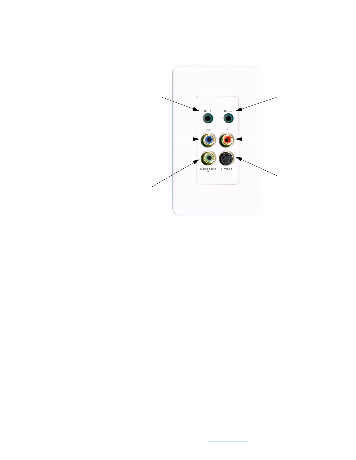
The front of the Panorama Video Port supports component, composite/digital audio,
and S-Video display interfaces. Figure 2-4 displays the front panel of the Panorama
Video Port.
IR In port- PANVP700 only
Pb port Component connections
Composite Y port Composite or
component video
connections or digital
audio connection
Figure 2-4 PANVP700 (front panel)
IR Out port
Pr port - Component
connections
S-Video port - S-Vide
connections
The type of video signal used determines how the connections on a Video Port are
used. The same type of video cables used to connect the source and PAN6400 VDC
must also be used to connect the Video Ports and the displays.
2-6
The ports on the front of the Panorama Video Ports include:
IR Out - connects an IR Emitter to the video source
IR In - connects the supplied IR Receiver (VP700 only)
Pb and Pr - connects component display devices
Composite/Y - connects composite or component display devices or digital audio
devices, depending on the configuration
S-Video - connects S-Video display devices. A special S-Video adaptor is required
to connect the source to the PAN6400 VDC. The red and blue cables of the adaptor
map to the Video Port’s S-Video port.
Whatever ports and cables you use on the PAN6400 VDC, duplicate that configuration
on the Video Ports.
The rear of the Video Ports have a CLC expansion slot and a Video Interface Module
(VIM).
All specifications subject to change without notification. All rights reserved. Copyright © 2006 NetStreams
Main +1 512.977-9393 / fax +1 512.977.9398 / Toll Free Technical Support +1 866-353-3496
3600 W. Parmer Lane, Suite 100; Austin, TX 78727 / www.netstreams.com.
Page 17
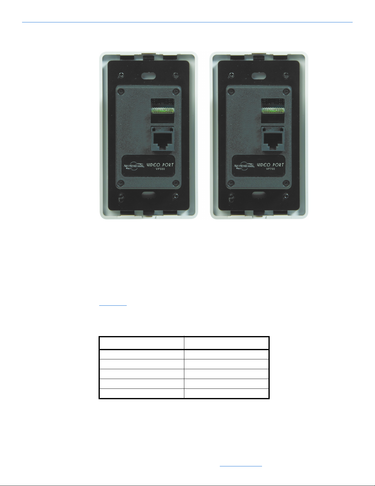
Figure 2-5 displays the rear panel of the Panorama Video Ports.
System Overview
Figure 2-5 PANVP500/PANVP700 (rear panel)
The CLC expansion slot helps optimize the video signal quality for each display by
attenuating the video signal to better suit the distance of your cable runs from the
PAN6400 VDC to the Video Port. The VIM uses an RJ45 connection to connect the
Video Port with the room outputs on the PAN6400 VDC.
Insert the provided chip that is closest to the length of cable you are running (see
Figure 2-6). Chips come in 50-, 250-, 500-, 750-, and 1000- ft. allotments as shown in
Table 2-1
. The Video Port ships with the 250 ft. chip inserted.
Table 2-1
CLC Usage
Chip Covers a Cable Length of
50 1 to 50 feet
250 51 to 250 feet
500 251 to 500 feet
750 501 to 750 feet
1000 751 to 1000 feet
All specifications subject to change without notification. All rights reserved. Copyright © 2006 NetStreams
Main +1 512.977-9393 / fax +1 512.977.9398 / Toll Free Technical Support +1 866-353-3496
3600 W. Parmer Lane, Suite 100; Austin, TX 78727 / www.netstreams.com.
2-7
Page 18
NetStreams Panorama System Installation Guide
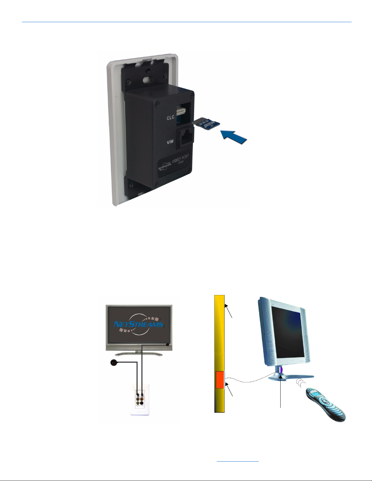
Figure 2-6 shows an example of how to insert a chip into the Panorama Video Port.
Figure 2-6 CLC chip (insertion)
Figure 2-7 shows the IR connection to and from the Video Ports. Connect the IR
Receiver to the Video Port and place it in a location where it can receive the IR signal
from the source remote. The best location is shaded from fluorescent light with the
dome facing the IR remote.
Place the IR Emitter over the IR window on the front of the display and connect it to
the Video Port.
Wall
IR
IR Receiver
Emitter
2-8
PANVP700
IR Emitter
PANVP700
Figure 2-7 Connecting PAN6400 VDC IR Receiver and Emitter
All specifications subject to change without notification. All rights reserved. Copyright © 2006 NetStreams
Main +1 512.977-9393 / fax +1 512.977.9398 / Toll Free Technical Support +1 866-353-3496
3600 W. Parmer Lane, Suite 100; Austin, TX 78727 / www.netstreams.com.
Page 19

Chapter
3
Configuring Standalone Installations
NetStreams Panorama system is much more than a typical video distribution system.
It is designed to offer full IR control of sources and displays without the need for a
third-party control system or IR infrastructure products and can distribute S/PDIF
audio. Panorama’s capability to function as a standalone video distribution and
control system provides unprecedented value over other products in the market that
simply do video switching.
The standalone configuration is useful for projects where a universal remote control
manages the video distribution system. The standalone configuration also greatly
simplifies control for third-party systems by combining video switching, source
control, and display control in one device. The model of Panorama Video Ports used
determines how the system is controlled. For example, in a project where the system is
controlled from each room with a universal remote control, use the VP700 Video Ports
to offer two-way IR (with an IR Receiver as well as an Emitter for the display). On the
other hand, if the project is a bar or restaurant where the rack location is the only
control point, the VP500 Video Ports work just fine.
There are many standalone configurations including the following:
component video
S-Video with coaxial digital (S/PDIF) audio
composite video with coaxial digital (S/PDIF) audio
cascading: adding displays by adding one or more additional PAN6400 VDC.
Configuring a Single PAN6400 VDC
The PAN6400 VDC can connect to video sources with component, composite, or
S-Video cables. It is important to note that Panorama does not transcode video
signals. If you connect your first source using component cables, you must connect the
display with component cables. The remaining three sources and the remaining
displays must also use component cables.
Connecting a cable to a PAN6400 VDC source input port defines that port for all
sources. For example, if source 1 has a composite video cable in the green (Y) port and
a digital audio cable in the red (Pr) port, the connections must remain consistent for
All specifications subject to change without notification. All rights reserved. Copyright © 2006 NetStreams
Main +1 512.977-9393 / fax +1 512.977.9398 / Toll Free Technical Support +1 866-353-3496
3600 W. Parmer Lane, Suite 100; Austin, TX 78727 / www.netstreams.com.
3-1
Page 20
NetStreams Panorama System Installation Guide
source inputs 2-4. (Do not put any video cable in the red port, or anything but a
composite cable in the green port.)
Because S-Video and composite video signals do not use all input ports, you can mix
them between sources. The S-Video adapter (provided) uses the blue (Pb) and red (Pr)
ports leaving the green (Y) port available for composite video distribution for a
different source.
However, you cannot connect digital audio through the PAN6400 VDC in this
configuration. In addition, the display would need to have available ports for
simultaneous S-Video and composite connections to accommodate the sources with
differing video connections. You can use the remote control for the display to toggle
between the two sources by selecting the source input.
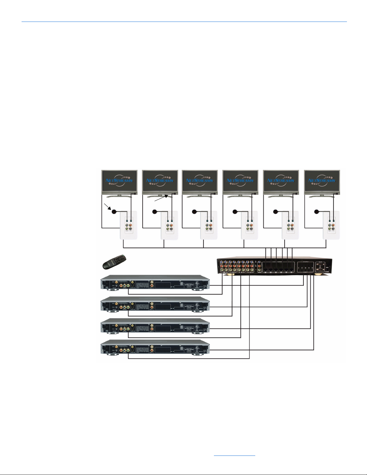
Figure 3-1 shows an example of how you might connect a video switch in a standalone
configuration.
Display 1 Display 2 Display 3 Display 4 Display 5 Display 6
IR Receiver
PANVP700
Figure 3-1 Video switch in a standalone environment
IR Emitter
VIDEO SOURCES
PAN6400
3-2
Component Video
The following procedures show how to connect a component video source to a
PAN6400 VDC. This is easily accomplished using one PAN6400 VDC. This
configuration is useful in environments that do not need audio, such as restaurants or
bars.
All specifications subject to change without notification. All rights reserved. Copyright © 2006 NetStreams
Main +1 512.977-9393 / fax +1 512.977.9398 / Toll Free Technical Support +1 866-353-3496
3600 W. Parmer Lane, Suite 100; Austin, TX 78727 / www.netstreams.com.
Page 21

L
egen
d
Configuring Standalone Installations
If you want to distribute the video to more than six displays, you can connect two or
more PAN6400 VDCs in cascade mode as discussed in Adding Additional Displays
(Cascade Mode) on page 3-7.
Since Panorama is being configured as a standalone system, the VP700s are highly
recommended. The IR Receiver (included with the VP700) permits control and
switching of the sources using the Panorama remote or a universal remote control. The
IR Emitters allow Panorama to control the display and source. Figure 3-2 shows a
complete wiring diagram for this configuration. For more detail on the ports on the rear
panel of the Panorama, see PAN6400 VDC on page 2-3.
IR Emitter
CAT5
Component
Display
u
y
IR
Receiver
PANVP700
Front
Back
t
r
w
IR
e
Emitter
PAN6400
Figure 3-2 Component video
To connect this component video configuration, complete the following steps:
1. Ensure power is off to all devices.
2. Connect the component cable from the component video out ports of the source to
the PAN6400 VDC source IN ports for that source. Match the jacks to the
appropriate PbPrY color-coded ports.
3. Connect an IR Emitter to the PAN6400 VDC IR OUTPUT port for the
corresponding source and place the emitter end over the IR window on the front of
the source.
All specifications subject to change without notification. All rights reserved. Copyright © 2006 NetStreams
Main +1 512.977-9393 / fax +1 512.977.9398 / Toll Free Technical Support +1 866-353-3496
3600 W. Parmer Lane, Suite 100; Austin, TX 78727 / www.netstreams.com.
Source
3-3
Page 22

NetStreams Panorama System Installation Guide
4. Connect the CAT5 cable from the display output on the PAN6400 VDC for that
source to the VIM port of a VP700.
5. Connect the VP700 attached to the PAN6400 VDC to the display using a
component cable.
You can route the video from the VP700 to an A/V Receiver and then the display.
6. Connect the IR Receiver to the IR IN port for that source on the VP700 and place
the IR Receiver where it can receive a signal from the remote. See Panorama
Ports: PANVP500 and PANVP700 on page 2-5 for information on effective IR
Receiver placement.
7. Connect an IR Emitter to the IR Out port of the VP700 and place the emitter end
over the IR window on the display.
8. Turn power on to all devices.
S-Video with Coaxial Digital (S/PDIF) Audio
The following procedures show you how to connect and distribute an S-Video and
coaxial digital (S/PDIF) audio source to Panorama. This can be easily accomplished
using one PAN6400 VDC. If you choose to distribute the audio and video to more than
six zones, more than one PAN6400 VDCs is necessary to provide the additional
DISPLAY OUTPUT ports, as discussed in Adding Additional Displays (Cascade
Mode) on page 3-7.
Video
When Panorama is installed as a standalone system, the VP700 Video Ports are highly
recommended, as the IR Receiver (included) permits control and switching of the
sources with a Panorama remote or universal remote control. Figure 3-3 shows a
3-4
All specifications subject to change without notification. All rights reserved. Copyright © 2006 NetStreams
Main +1 512.977-9393 / fax +1 512.977.9398 / Toll Free Technical Support +1 866-353-3496
3600 W. Parmer Lane, Suite 100; Austin, TX 78727 / www.netstreams.com.
Page 23

Configuring Standalone Installations
complete wiring diagram for this configuration. For more detail on the ports on the rear
panel of the Panorama, see PAN6400 VDC on page 2-3.
Legend
IR Emitter
CAT5
S-Video
Coaxial audio
Speaker
5.1 or higher
channel speaker outputs
a
PANVP700
Back
we
t
i
IR
Receiver
u
o
y
PANVP700
Front
IR
r
Emitter
Display
PAN6400
Source
This configuration does not
work for component video.
Figure 3-3 S-Video and coaxial digital (S/PDIF) audio
To make the connections for S-Video and digital audio, complete the following steps:
1. Ensure power is off to all devices.
2. Connect the S-Video cable (provided with the source) from the source to the
S-Video adapter (provided) and connect the blue (Pb) and red (Pr) RCA
connections to the PAN6400 VDC IN ports for that source.
3. Connect the coaxial digital (S/PDIF) cable from the source to the PAN6400 VDC
IN port (green) for that source.
4. Connect an IR Emitter to the PAN6400 VDC IR OUTPUT port for that source and
place the emitter end over the IR window on the front of the source.
5. Connect the CAT5 cable from the room output on the PAN6400 VDC to the VIM
port of the VP700.
6. Use an S-Video cable to connect the VP700 to the display.
You can also route the video from the VP700 to an A/V Receiver and then to the
display.
7. Connect the Y/Composite port of the VP700 to the Digital Audio In of the A/V
Receiver.
All specifications subject to change without notification. All rights reserved. Copyright © 2006 NetStreams
Main +1 512.977-9393 / fax +1 512.977.9398 / Toll Free Technical Support +1 866-353-3496
3600 W. Parmer Lane, Suite 100; Austin, TX 78727 / www.netstreams.com.
3-5
Page 24

NetStreams Panorama System Installation Guide
8. Connect the IR Receiver to the IR IN port on the VP700 and place the IR Receiver
where it can receive a signal from the remote. See Panorama Video Ports:
PANVP500 and PANVP700 on page 2-5 for information on effective IR Receiver
placement.
9. Connect an IR Emitter to the IR Out port of the VP700 and place the emitter end
over the IR window on the display.
10. Connect 5.1 or higher channel speakers from the output ports of the A/V Receiver.
11. Turn power on to all devices.
Composite Video with Coaxial Digital (S/PDIF) Audio
The following procedures show how to connect composite video and coaxial digital
(S/PDIF) audio to easily provide both video and audio distribution from one PAN6400
VDC. If you want to distribute the audio and video to more than six zones, you can
connect two or more PAN6400 VDCs in cascade mode as discussed in Adding
Additional Displays (Cascade Mode) on page 3-7.
When Panorama is installed as a standalone system, the VP700 Video Ports are highly
recommended as the IR Receiver permits control and switching of the sources with a
Panorama or universal remote control. Figure 3-4 shows a complete wiring diagram
for this configuration. For more detail on the ports on the rear panel of the Panorama,
see PAN6400 VDC on page 2-3.
Legend
IR Emitter
CAT5
Composite
Coaxial audio
Speaker
5.1 or higher
i
IR
Receiver
channel speaker outputs
a
o
y
PANVP700
Back
t
u
PANVP700
Front
we r
Display
PAN6400
IR
Emitter
3-6
Source
Figure 3-4 Composite video and coaxial digital (S/PDIF) audio
All specifications subject to change without notification. All rights reserved. Copyright © 2006 NetStreams
Main +1 512.977-9393 / fax +1 512.977.9398 / Toll Free Technical Support +1 866-353-3496
3600 W. Parmer Lane, Suite 100; Austin, TX 78727 / www.netstreams.com.
Page 25

Configuring Standalone Installations
NOTE
NOTE
To make the connections for composite video and digital audio, complete the
following steps:
1. Ensure power is off to all devices.
2. Connect the composite video cable from the video out port of the source to the
PAN6400 VDC IN port (red) for that source.
The composite video
cable can be plugged
into the Pb, Pr, or Y IN
ports. However, once a
port has been used for
composite, all sources
must use that port. For
example, if source 1
plugs the composite
cable into the red (Pr)
port, the three remaining
sources must use the Pr
port for composite
cables.
3. Connect the coaxial digital (S/PDIF) cable from the source to the PAN6400 VDC
IN port (green) for that source.
4. Connect an IR Emitter to the PAN6400 VDC IR OUTPUT port for the source and
place the emitter end over the IR window on the front of the source.
5. Connect the CAT5 cable from the display output on the PAN6400 VDC to the VIM
port on the VP700.
6. Connect the VP700 to the display using a composite cable.
You can also route the video from the VP700 to an A/V Receiver and then to the
display.
7. Connect the Y/Composite port of the VP700 to the digital audio in of the A/V
Receiver.
8. Connect the IR Receiver to the IR IN port on the VP700 and place the IR Receiver
where it can receive a signal from the remote. See Panorama Video Ports:
PANVP500 and PANVP700 on page 2-5 for information on effective IR Receiver
placement.
9. Connect an IR Emitter to the IR Out port of the VP700 and place the emitter end
over the IR window on the display.
10. Connect 5.1 or higher channel speakers from the output ports of the A/V Receiver.
11. Turn power on to all devices.
Adding Additional Displays (Cascade Mode)
Only the number of
displays can be
increased by cascading,
not the number of
sources.
All specifications subject to change without notification. All rights reserved. Copyright © 2006 NetStreams
Cascading two or more PAN6400 VDCs allows you to distribute video and audio
signal to more than six displays. You can display four sources to hundreds of displays.
This can be useful in commercial environments, such as sports bars or airports, where
audio is routed separately and the video needs to be displayed on many displays.
As many as 100 PAN6400 VDCs can be cascaded in this manner, for a total of 600
displays.
3-7
Main +1 512.977-9393 / fax +1 512.977.9398 / Toll Free Technical Support +1 866-353-3496
3600 W. Parmer Lane, Suite 100; Austin, TX 78727 / www.netstreams.com.
Page 26

NetStreams Panorama System Installation Guide
Figure 3-5 shows an example of how you might connect a VDC to more than six
displays in a standalone, cascaded configuration.
Displays 1-6 Displays 7-12
PANVP700 PANVP700
PAN6400 VDC
Displays 7-12
Sources
Figure 3-5 Video switch in a standalone, cascaded environment
PAN6400 VDC
Displays 1-6
Any type of video signal can be cascaded. Zones 1-6 and zones 7-12 in Figure 3-6 each
show connections for one source, display, and A/V Receiver. To connect additional
sources, displays, or A/V Receivers, connect them in the same fashion as the ones
3-8
All specifications subject to change without notification. All rights reserved. Copyright © 2006 NetStreams
Main +1 512.977-9393 / fax +1 512.977.9398 / Toll Free Technical Support +1 866-353-3496
3600 W. Parmer Lane, Suite 100; Austin, TX 78727 / www.netstreams.com.
Page 27

Configuring Standalone Installations
shown in Figure 3-6. For more detail on the ports on the rear panel of the Panorama,
see PAN6400 VDC on page 2-3.
Legend
IR Emitter
CAT5
S-Video
Coaxial audio
Speaker
5.1 or 7.1 channel
speaker outputs
Display Display
j
Zones 7-12Zones 1-6
o
IR Emitter IR Emitter
IR Receiver IR Receiver
h
a
A/V Receiver A/V Receiver
g
i
PAN6400
VDC (1)
e
u
r
w
t
y
IR Emitter
Source
h
s
5.1 or 7.1 channel
speaker outputs
j
d
f
g
PANVP700PANVP700
PAN6400
VDC (2)
Figure 3-6 Cascaded installation: S-Video and coaxial audio
To make the connections for a standalone, cascaded, S-Video installation, complete the
following steps:
1. Ensure power is off to all devices.
2. Connect the S-Video cable (provided with the source) from the source to the
S-Video adapter (provided) and connect the blue (Pb) and red (Pr) RCA
connections to the PAN6400 VDC (1) video input connections.
3. Connect a set of RCA video cables from the video output connections on the
PAN6400 VDC (1) to the respectively colored input ports for that source on the
PAN6400 VDC (2).
This distributes the video to more than six zones.
4. Connect the coaxial digital (S/PDIF) cable from the source to the PAN6400 VDC
IN port (green) for that source on the PAN6400 VDC (1).
5. Connect another coaxial digital (S/PDIF) cable from the green output port on the
PAN6400 VDC (1) to the green input port for that source on the PAN6400
VDC (2).
6. Connect an IR Emitter to the PAN6400 VDC (1) IR OUTPUT port for the source
and place the emitter end over the IR window on the front of the source.
7. Connect a 3.5 mm jack cable from the PAN6400 VDC (1) IR INPUT for the source
to the PAN6400 VDC (2) IR OUTPUT for the source.
All specifications subject to change without notification. All rights reserved. Copyright © 2006 NetStreams
Main +1 512.977-9393 / fax +1 512.977.9398 / Toll Free Technical Support +1 866-353-3496
3600 W. Parmer Lane, Suite 100; Austin, TX 78727 / www.netstreams.com.
3-9
Page 28

NetStreams Panorama System Installation Guide
8. Connect the Ethernet CAT5 cable from the room output for the source on the
PAN6400 VDC (1) to the VIM port of the VP700 you are using to connect to a
display.
9. Use an S-Video cable to connect the VP700 attached to the PAN6400 VDC (1) to
the display.
You can also route the video from the VP700 to an A/V Receiver and then to the
display.
10. Connect the Y/Composite port of the VP700 attached to the PAN6400 VDC (1) to
the Digital Audio In of the A/V Receiver.
11. Connect the Ethernet CAT5 cable from the room output for the source on the
PAN6400 VDC (2) to the VIM port of the VP700 you are using to connect to a
display.
12. Use an S-Video cable to connect the VP700 attached to the PAN6400 VDC (1) to
the display.
You can also route the video from the VP700 to an A/V Receiver and then to the
display.
13. Connect the Y/Composite port of the VP700 attached to the PAN6400 VDC (1) to
the Digital Audio In of the A/V Receiver.
14. Connect the IR Receiver supplied with the VP700 that is attached to the PAN6400
VDC (1) to the IR IN port on the VP700 and place the IR Receiver dome where it
can receive an IR signal from the remote. See Panorama Video Ports: PANVP500
and PANVP700 on page 2-5 for information on effective IR Receiver placement.
Repeat for each VP700.
15. Connect an IR Emitter to the IR Out port of the VP700 attached to the PAN6400
VDC (2) and place the emitter end over the IR window on the display.
Repeat for each VP700.
16. Connect 5.1 or 7.1 channel speakers from the output ports of the A/V Receiver.
Repeat for each A/V Receiver.
17. Turn power on to all devices.
3-10
All specifications subject to change without notification. All rights reserved. Copyright © 2006 NetStreams
Main +1 512.977-9393 / fax +1 512.977.9398 / Toll Free Technical Support +1 866-353-3496
3600 W. Parmer Lane, Suite 100; Austin, TX 78727 / www.netstreams.com.
Page 29

Chapter
4
Integrating with NetStreams Musica 5000 Series
Panorama PAN6400 VDC and Musica MU5066ADC integrate to provide video and
analog audio. You can connect as many as three PAN6400 VDCs to as many as three
Musica MU5066ADCs for 18-zone coverage.
When integrated with Musica, the PAN6400 VDC can distribute component, S-Video,
or composite video signals. When integrated, the Musica MU5066ADC system
handles analog audio distribution.
Integrating a Single Musica MU5066ADC and PAN6400 VDC
The PAN6400 VDC can connect to video sources with component, composite, or
S-Video cables. It is important to note that Panorama does not transcode video
signals. If you connect your first source using component cables, you must connect the
display with component cables. The remaining three sources and the remaining
displays must also use component cables.
Connecting a cable to a PAN6400 VDC source input port defines that port for all
sources. For example, if Source 1 has a composite video cable in the green (Y) port
and a digital audio cable in the red (Pr) port, the connections must remain consistent
for source inputs 2-4. (Do not put any video cable in the red port, or anything but a
composite cable in the green port.)
Because S-Video and composite video signals do not use all input ports, you can mix
them between sources. The S-Video adapter (provided) uses the blue (Pb) and red (Pr)
ports leaving the green (Y) port available for composite video distribution for a
different source.
However, you cannot connect digital audio through the PAN6400 VDC in this
configuration. In addition, the display would need to have available ports for
simultaneous S-Video and composite connections to accommodate the sources with
differing video connections. You can use the remote control for the display to toggle
between the two sources by selecting the source input.
When integrating Panorama and Musica, the Musica MU5066KP routes the IR signal.
Therefore, NetStreams recommends the use of VP500 Video Ports when integrating
Panorama and Musica.
All specifications subject to change without notification. All rights reserved. Copyright © 2006 NetStreams
Main +1 512.977-9393 / fax +1 512.977.9398 / Toll Free Technical Support +1 866-353-3496
3600 W. Parmer Lane, Suite 100; Austin, TX 78727 / www.netstreams.com.
4-1
Page 30

NetStreams Panorama System Installation Guide
Figure 4-1 shows a typical method of integrating the two systems. Notice that analog
audio is connected through the Musica ADC and the video (composite in this case) is
connected through the PAN6400 VDC. For more detail on the ports on the rear panel
of the Panorama, see PAN6400 VDC on page 2-3.
Legend
IR Emitter &
null modem
CAT5
Composite
Coaxial audio
Analog audio
Power and
speaker
PANVP500
Back
e
r
y
Display
u
i
PANVP500
Front
Speakers
Musica Keypad
Front Back
t
s
a
o
Musica
MU5066ADC
PAN6400
VDC
4-2
w
Figure 4-1 Integrated with Musica
To make this connection, complete the following steps:
1. Ensure power is off to all devices.
2. Connect the video (composite in this example) from the source to the PAN6400
VDC.
3. Connect the analog audio from the source to the Musica MU5066ADC.
You must connect to the same source number (S1 - S4) that the video is connected
to. If a source is connected to the S2 ports for video on the PAN6400 VDC, that
source must be connected to the S2 ports on the Musica MU5066ADC.
All specifications subject to change without notification. All rights reserved. Copyright © 2006 NetStreams
Main +1 512.977-9393 / fax +1 512.977.9398 / Toll Free Technical Support +1 866-353-3496
3600 W. Parmer Lane, Suite 100; Austin, TX 78727 / www.netstreams.com.
Source
Page 31

Integrating with NetStreams Musica 5000 Series
4. Connect an IR Emitter to the Musica MU5066ADC IR OUTPUT port and place
the emitter end over the IR window on the front of the source.
5. Connect a null modem cable from the RS-232C port of the Musica MU5066ADC
to the RS-232 IO1 port of the PAN6400 VDC.
6. Connect a CAT5 cable from the appropriate DISPLAY OUTPUT port on the
PAN6400 VDC to the VIM port of the VP500 you are using to connect to a display.
7. Connect the video (composite in this example) from the VP500 output to the
display.
8. Connect an IR Emitter to the IR Out port of the VP500 and place the emitter end
over the IR window on the display.
9. Connect a CAT5 cable from the appropriate room CLASS 2 WIRING port on the
Musica MU5066ADC to the ADC port of the Musica Keypad.
Use the same output number on both the PAN6400 VDC and the Musica
MU5066ADC ports. Otherwise the system will not synchronize the display and the
audio connected to the VP500 and the Musica Keypad.
10. Connect a 16/4 cable with 2-pin Phoenix connectors from the PWR port on the
Musica Keypad to the appropriate display ROOM POWER port on the Musica
MU5066ADC.
A 16/4 and CAT5 Siamese (combo) cable is easier to run and less likely to break.
You can use a 16/2 cable since two wires on the 16/4 cable are clipped and not
used. However, using the 16/4 cable allows for easy future expansion or upgrades.
11. Connect speakers using 4-pin Phoenix connectors from the rear of the Musica
MU5066KP Keypad to the left and right speakers.
12. Turn power on to all devices.
Adding Additional Input Ports (Mirrored Mode)
Mirroring two PAN6400 VDCs provides a total of six inputs per source over which
you can distribute signals. This allows you to distribute synchronized component video
signals and digital audio. The Musica MU5066ADC sends RS-232 commands to a
PAN6400 VDC to which it is connected and additional PAN6400 VDCs mirror the
actions of the first PAN6400 VDC.
Although you can mirror the PAN6400 VDC with any supported video signal, most
installations use mirroring to distribute component video with coaxial digital audio
(S/PDIF) while Musica distributes analog audio. The digital audio signal distributed
from the PAN6400 VDC can be used with a digital surround sound home theater.
Figure 4-2 and the associated steps show how to wire a Musica MU5066ADC and two
PAN6400 VDCs. The Musica MU5066KP provides IR capability, so two VP500s
connect the video and audio. The IR input port of a VP700 is disabled if included in an
All specifications subject to change without notification. All rights reserved. Copyright © 2006 NetStreams
Main +1 512.977-9393 / fax +1 512.977.9398 / Toll Free Technical Support +1 866-353-3496
3600 W. Parmer Lane, Suite 100; Austin, TX 78727 / www.netstreams.com.
4-3
Page 32

NetStreams Panorama System Installation Guide
installation with a Musica MU5066KP. For more detail on the ports on the rear panel
of the Panorama, see PAN6400 VDC on page 2-3.
Legend
IR Emitter and
null modem
CAT5
Component
Coaxial audio
Speaker and
analog audio
Power and
speaker
i
Display
PANVP500
Back BackFrontFront
a
o
5.1 or 7.1 channel
speaker outputs
f
d
PANVP500
s
j
Musica Keypad
Front Back
h
g
y
t
IR Emitter
PAN6400 (1)
PAN6400 (2)
u
e
r
Source
w
Figure 4-2 Integrating PAN6400 VDC with Musica MU5066ADC in mirrored mode
To integrate PAN6400 VDC with Musica MU5066ADC in mirrored mode, complete
the following steps:
4-4
1. Ensure power is off to all devices.
All specifications subject to change without notification. All rights reserved. Copyright © 2006 NetStreams
Main +1 512.977-9393 / fax +1 512.977.9398 / Toll Free Technical Support +1 866-353-3496
3600 W. Parmer Lane, Suite 100; Austin, TX 78727 / www.netstreams.com.
Page 33

Integrating with NetStreams Musica 5000 Series
2. Connect a component video cable from the component video out ports of the
source to the PAN6400 VDC (2) IN ports for that source.
3. Connect the coaxial digital (S/PDIF) audio cable from the source to the PAN6400
VDC (1) IN port (green) for that source.
4. Connect the analog audio from the source to the Musica MU5066ADC.
The Musica and PAN6400 VDC devices must all connect to the same number
source input (S1 - S4). If you connect the video cables to the S2 ports, the coaxial
digital (S/PDIF) cable and the analog cables must also connect to the S2 ports on
the respective devices.
5. Connect an IR Emitter to the Musica MU5066ADC IR OUTPUT port for the
source and place the emitter end over the IR window on the front of the source.
6. Connect a null modem cable from the RS-232C port of the Musica MU5066ADC
to the RS-232 IO1 port of the PAN6400 VDC (1).
7. Connect a null modem cable from the RS-232 IO2 port of the PAN6400 VDC (1)
to the RS-232 IO1 port of the PAN6400 VDC (2).
8. Connect a CAT5 cable from the DISPLAY OUTPUT port for that source on the
PAN6400 VDC (2) to the VIM port of a VP500.
9. Connect the VP500 attached to PAN6400 VDC (2) to the display using a
component cable.
You can also route the video from the VP500 to the A/V Receiver and then to the
display.
10. Connect an IR Emitter to the IR Out port of the VP500 attached to PAN6400
VDC (2) and place the emitter end over the IR window on the display.
11. Connect a CAT5 cable from the DISPLAY OUTPUT for that source on the
PAN6400 VDC (1) to the VIM port of a VP500.
12. Connect a coaxial digital (S/PDIF) cable from the Y/Composite port of the VP500
attached to the PAN6400 VDC (1) to the Digital Audio In of the A/V Receiver.
13. Connect 5.1 or 7.1 channel speakers from the output ports of the A/V Receiver.
14. Connect a CAT5 cable from the appropriate room CLASS 2 WIRING port on the
Musica MU5066ADC to the ADC port of the Musica Keypad.
Use the same output number on both the PAN6400 VDC and the Musica
MU5066ADC ports. Otherwise the system will not synchronize the display and the
audio connected to the VP500 and the Musica Keypad.
15. Connect a 16/4 cable with 2-pin Phoenix connectors from the PWR port on the
Musica Keypad to the appropriate display ROOM POWER port on the Musica
MU5066ADC.
A 16/4 and CAT5 Siamese (combo) cable is easier to run and less likely to break.
You can use a 16/2 cable since two wires on the 16/4 cable are clipped and not
used. However, using the 16/4 cable allows for easy future expansion or upgrades.
16. Connect speakers using 4-pin Phoenix connectors from the rear of the Musica
MU5066KP Keypad to the left and right speakers.
17. Turn power on to all devices.
All specifications subject to change without notification. All rights reserved. Copyright © 2006 NetStreams
Main +1 512.977-9393 / fax +1 512.977.9398 / Toll Free Technical Support +1 866-353-3496
3600 W. Parmer Lane, Suite 100; Austin, TX 78727 / www.netstreams.com.
4-5
Page 34

NetStreams Panorama System Installation Guide
Adding Additional Displays (Cascade Mode)
One Musica and one NetStreams Panorama system together provide for the
distribution of four audio and video sources to as many as six zones. For the
distribution of four sources to as many as 18 zones, integrate up to three Panorama
PAN6400 VDC and Musica MU5066ADC pairs.
Connect each additional PAN6400 VDC and Musica MU5066ADC with null modem
RS-232 cables from the IO2 to IO1 ports as discussed above.
A null modem RS-232 cable connects two PAN6400 VDCs to provide a total of 12
displays (zones) (NS-MUXK-12) and the null modem RS-232 cable included in the
Musica 18-Zone Expansion Kit (NS-MUXK-18) connects three PAN6400 VDCs to
provide 18 displays. The RS-232 cable connects into the PAN6400 VDC I01 port on
all VDCs.
The analog audio expansion cables (also provided in the Musica expansion kit)
connect to all Musica MU5066ADCs. Figure 4-3 focuses on integrating Panorama and
Musica, including IR connections. The figure does not show the analog digital cables
connecting the Musica MU5066ADC. See Application Note 030017 on the
NetStreams website for a figure that includes those cables as well as complete
information on expanding Musica to 18 displays and keypads.
Legend
IR Emitter and
null modem
CAT5 from VP
CAT5 from
keypad
Component
Component
Figure 4-3 shows how to integrate two additional PAN6400 VDCs with a Musica
system in cascade mode.
Zones 1-6 Zones 7-12 Zones 12-18
Display
IR Emitter
Musica
keypad
PANVP500
4-6
PAN6400 VDCs Musica MU5066ADCs
Figure 4-3 Integrating PAN6400 VDC with Musica MU5066ADC in cascade mode
All specifications subject to change without notification. All rights reserved. Copyright © 2006 NetStreams
Main +1 512.977-9393 / fax +1 512.977.9398 / Toll Free Technical Support +1 866-353-3496
3600 W. Parmer Lane, Suite 100; Austin, TX 78727 / www.netstreams.com.
MUXK-18 null
modem cable
Null modem
cable
IR Emitters
Page 35

Integrating with NetStreams Musica 5000 Series
Integrating the Musica MUR2EM Network Interface
When integrating the Panorama with the NetStreams Musica 5000 Series Multi-Room
Audio & Control system, you can use the Musica MUR2EM Network Interface to
provide web browser-based control of your system (see Figure 4-4).
Legend
Null modem
CAT5
Home Network Switch
e
w
Power
r
Musica MU5066ADC
Computer SystemMUR2EM
t
PAN6400 VDC
Figure 4-4 PAN6400 VDC and Musica MUR2EM
To connect the MUR2EM for IP configuration, complete the following steps:
1. Ensure power is off to all devices.
2. Connect the MUR2EM to the IO2 port of the PAN6400 VDC using the null modem
cable provided.
3. Connect the Musica MU5066ADC to the IO1 port of the PAN6400 VDC using a
null modem cable.
4. Connect the Ethernet port of the MUR2EM to the home network switch with CAT5
cable.
5. Connect the Ethernet port of the computer to the home network switch with CAT5
cable.
6. Ensure all power cables are plugged in.
7. Start the computer.
For further information on the MUR2EM (such as configuring the IP address), see the
Musica MUR2EM Installation Guide.
All specifications subject to change without notification. All rights reserved. Copyright © 2006 NetStreams
Main +1 512.977-9393 / fax +1 512.977.9398 / Toll Free Technical Support +1 866-353-3496
3600 W. Parmer Lane, Suite 100; Austin, TX 78727 / www.netstreams.com.
4-7
Page 36

NetStreams Panorama System Installation Guide
4-8
All specifications subject to change without notification. All rights reserved. Copyright © 2006 NetStreams
Main +1 512.977-9393 / fax +1 512.977.9398 / Toll Free Technical Support +1 866-353-3496
3600 W. Parmer Lane, Suite 100; Austin, TX 78727 / www.netstreams.com.
Page 37

Chapter
5
Integrating Panorama with DigiLinX
The NetStreams Panorama system can easily be integrated with the NetStreams
DigiLinX IP-Based Multi-Room Audio and Control system or other third-party
control systems. In this scenario, the Panorama system distributes high-definition
video over its balanced, line-level connection and provides IR control of each display.
Panorama learns and stores the IR necessary for display control and source switching.
DigiLinX provides display and source control over the network, as well as audio
distribution.
If integrating with a third-party control system, the wiring follows the same
configuration as the DigiLinX system, in particular when connecting RS-232 cables.
A DigiLinX system includes ControLinX, MediaLinX, PowerLinX™, SwitchLinX™,
and SpeakerLinX components to distribute and control video and audio. ControLinX
connects to the RS-232 port labeled IO2 on the PAN6400 VDC to provide control of
the video source switching and video displays. Connect the audio outputs from each
video source to a MediaLinX for distribution of the audio over TCP/IP and control of
the video source. You can install either one MediaLinX MLA101 device per source or
an MLA4000 per every four sources. Any network product or device with a web
browser and Adobe Flash® can control either MediaLinX device. ControLinX and
MediaLinX are connected to SwitchLinX, which manages the network.
Integrating a Single DigiLinX System and PAN6400 VDC
The PAN6400 VDC can connect to video sources with component, S-Video, or The
PAN6400 VDC can connect to video sources with component, composite, or S-Video
cables. It is important to note that Panorama does not transcode video signals. If you
connect your first source using component cables, you must connect the display with
component cables. The remaining three sources and the remaining displays must also
use component cables.
Connecting a cable to a PAN6400 VDC source input port defines that port for all
sources. For example, if Source 1 has a composite video cable in the green (Y) port
and a digital audio cable in the red (Pr) port, the connections must remain consistent
for source inputs 2-4. (Do not put any video cable in the red port, or anything but a
composite cable in the green port.)
All specifications subject to change without notification. All rights reserved. Copyright © 2006 NetStreams
Main +1 512.977-9393 / fax +1 512.977.9398 / Toll Free Technical Support +1 866-353-3496
3600 W. Parmer Lane, Suite 100; Austin, TX 78727 / www.netstreams.com.
5-1
Page 38

NetStreams Panorama System Installation Guide
Because S-Video and composite video signals do not use all input ports, you can mix
them between sources. The S-Video adapter (provided) uses the blue (Pb) and red (Pr)
ports leaving the green (Y) port available for composite video distribution for a
different source.
However, you cannot connect digital audio through the PAN6400 VDC in this
configuration. In addition, the display would need to have available ports for
simultaneous S-Video and composite connections to accommodate the sources with
differing video connections. You can use the remote control for the display to toggle
between the two sources by selecting the source input.
Figure 5-1 shows an example of the components you might use when integrating a
NetStreams Panorama system and DigiLinX. Not all DigiLinX components are shown.
IR
Receiver
PANVP700
Display
Speakers
SpeakerLinX
IR Emitter
ControLinX
MediaLinX
Front Back
SwitchLinX
5-2
PAN6400 VDC
IR Emitters
Sources
Figure 5-1 Video switch integrated with DigiLinX
All specifications subject to change without notification. All rights reserved. Copyright © 2006 NetStreams
Main +1 512.977-9393 / fax +1 512.977.9398 / Toll Free Technical Support +1 866-353-3496
3600 W. Parmer Lane, Suite 100; Austin, TX 78727 / www.netstreams.com.
Page 39

Integrating Panorama with DigiLinX
The following procedures show how to integrate Panorama and DigiLinX systems.
Figure 5-2 shows Panorama integrated with DigiLinX using VP700s for IR passthrough. If using VP500, there is no IR pass-through from the displays and you do not
need to connect IR extension cables between the Panorama and the MediaLinX.
For more detail on the ports on the rear panel of the PAN6400 VDC, see PAN6400
VDC on page 2-3.
Legend
IR Emitter and
null modem
CAT5
Component
Coaxial audio
Speaker
i
o
IR
Receiver
Display
a
Front Back
PANVP700
u
IR Emitter
SwitchLinX
TouchLinX
SpeakerLinX
s
ControLinX
sss
Speakers
y
MediaLinX
PAN6400 VDC
IR Emitter
r
w
Figure 5-2 Integrated with DigiLinX with IR pass-through from displays
e
The following procedure focuses on the steps integral to integrating Panorama and
DigiLinX. For complete instructions on installing a DigiLinX system, see the DigiLinX
Installation & Design Guide from the dealer section of the NetStreams website
All specifications subject to change without notification. All rights reserved. Copyright © 2006 NetStreams
Main +1 512.977-9393 / fax +1 512.977.9398 / Toll Free Technical Support +1 866-353-3496
3600 W. Parmer Lane, Suite 100; Austin, TX 78727 / www.netstreams.com.
t
Source
5-3
Page 40

NetStreams Panorama System Installation Guide
NOTE
(www.netstreams.com). To integrate a NetStreams Panorama system with a DigiLinX
system, complete the following steps:
Select the Panorama
driver for the
ControLinX when
configuring the
DigiLinX system using
the DigiLinX Dealer
Setup Program 1.5 or
higher. You cannot
configure the
ControLinX device to
control the Panorama
video switching and
displays until the
connections are made.
The DigiLinX devices
must be running
firmware version 1.25
or higher.
1. Ensure power is off to all devices.
2. Connect the component cable from the component video out ports of the source to
the PAN6400 VDC IN ports for that source.
3. Connect the coaxial digital (S/PDIF) or analog audio cable from each video source
to each MediaLinX.
4. Connect an IR Emitter to the PAN6400 VDC IR OUTPUT port for that source and
place the emitter end over the IR window on the front of the source.
For example, if the video source is connected to the PAN6400 VDC source IN port
S2, then plug the IR Emitter into IR OUTPUT S2.
5. Connect an IR extension cable (3.5 mm to 3.5 mm, shipped with Panorama) from
the PAN6400 VDC IR INPUT port for that source (in the example above, this
would be IR INPUT S2) to the MediaLinX IR/RS-232 port.
6. Connect the 3.5 mm to RS-232 cable (included with ControLinX) from the
RS-232C port of the ControLinX to a null modem cable and connect it to the
RS-232 IO2 port on the rear panel of the PAN6400 VDC.
This allows a DigiLinX system to control Panorama functions.
7. Connect the CAT5 cable from the room output on the PAN6400 VDC to the VIM
port on the VP700.
This procedure assumes you are using VP700s for IR pass-through functionality.
8. Connect the VP700 to the display using a component cable.
9. Connect the IR Receiver to the IR IN port on the VP700 and place the IR Receiver
where it can receive a signal from the remote. See Panorama Video Ports:
PANVP500 and PANVP700 on page 2-5 for information on effective IR Receiver
placement.
5-4
10. Connect an IR Emitter to the IR Out port of the VP700 and place the emitter end
over the IR window on the display.
11. Connect CAT5 Ethernet cables from each MediaLinX, TouchLinX, and
SpeakerLinX and from the ControLinX to the SwitchLinX-managed Ethernet
switch.
This provides the DigiLinX devices with network connectivity.
12. Continue connecting the rest of the DigiLinX system as per the DigiLinX Design &
Installation Guide.
13. Turn power on to all devices.
Adding Additional Input Ports (Mirrored Mode)
Mirroring two PAN6400 VDCs provides a total of six inputs per source over which
you can distribute signals. This allows you to distribute synchronized component video
signals and digital audio. One ControLinX controls both PAN6400 VDCs by sending
All specifications subject to change without notification. All rights reserved. Copyright © 2006 NetStreams
Main +1 512.977-9393 / fax +1 512.977.9398 / Toll Free Technical Support +1 866-353-3496
3600 W. Parmer Lane, Suite 100; Austin, TX 78727 / www.netstreams.com.
Page 41

Integrating Panorama with DigiLinX
RS-232 commands to the PAN6400 VDC it is connected to and the additional
PAN6400 VDCs mirror the actions of the first PAN6400 VDC.
Although you can mirror the PAN6400 VDC with any supported video signal, most
installations use mirroring to distribute component video with coaxial digital audio
(S/PDIF) while the DigiLinX system distributes analog audio. Although the DigiLinX
system can read digital audio, it only outputs analog audio. When the PAN6400 VDC
distributes digital audio, the system can support a digital surround sound home theater.
Figure 5-3 and the associated steps show how to wire a DigiLinX system and two
PAN6400 VDCs. Use a VP700 to connect the display and provide IR capability and a
VP500 to connect the digital audio. For more detail on the ports on the rear panel of the
Panorama, see PAN6400 VDC on page 2-3.
Legend
IR Emitter and
null modem
CAT5
Component
Coaxial audio
Speaker and
analog audio
Power and
speaker
Display
f
Front
VP700
IR Receiver
IR Emitter
g
Back
d
5.1 or 7.1 channel
speaker outputs
k
j
VP500
BackFront
h
SwitchLinX
Speakers
SpeakerLinX
ControLinX
TouchLinX
MediaLinX
l
i
PAN6400 (1)
yu
s
PAN6400 (2)
IR Emitter
t
e
w
Source
Figure 5-3 Integrating PAN6400 VDC with DigiLinX in mirrored mode
All specifications subject to change without notification. All rights reserved. Copyright © 2006 NetStreams
Main +1 512.977-9393 / fax +1 512.977.9398 / Toll Free Technical Support +1 866-353-3496
3600 W. Parmer Lane, Suite 100; Austin, TX 78727 / www.netstreams.com.
a
o
r
5-5
Page 42

NetStreams Panorama System Installation Guide
To integrate a PAN6400 VDC with DigiLinX in mirrored mode, complete the
following steps:
1. Ensure power is off to all devices.
2. Connect a component video cable from the component video out ports of the
source to the PAN6400 VDC (2) IN ports for that source.
3. Connect the coaxial digital (S/PDIF) audio cable from the source to the PAN6400
VDC (1) IN port (green) for that source.
4. Connect the analog audio cable from the video source to a MediaLinX.
5. Connect an IR Emitter to the PAN6400 VDC (2) IR OUTPUT port for the source
and place the emitter end over the IR window on the front of the source.
6. Connect an IR extension cable (3.5 mm to 3.5 mm, shipped with Panorama) from
the PAN6400 VDC (2) IR INPUT for the source to the PAN6400 VDC (1) IR
OUTPUT for the source.
7. Connect an IR extension cable (3.5 mm to 3.5 mm, shipped with Panorama) from
the PAN6400 VDC (2) C (Common) IR INPUT to the PAN6400 VDC (1) C
(Common) IR OUTPUT.
8. Connect an IR extension cable (3.5 mm to 3.5 mm, shipped with Panorama) from
the PAN6400 VDC (1) IR INPUT port for that source to the MediaLinX IR/RS-232
port.
9. Connect the 3.5 mm to RS-232 cable (included with ControLinX) from the
IR/RS-232 port of the ControLinX to a null modem cable and connect it to the
RS-232 IO2 port on the rear panel of PAN6400 VDC (2).
This allows a DigiLinX system to control Panorama functions.
10. Connect a null modem cable from the RS-232 IO1 port of the PAN6400 VDC (2)
to the RS-232 IO2 port of the PAN6400 VDC (1).
This allows the two PAN6400 VDCs to mirror each other.
11. Connect a CAT5 cable from the DISPLAY OUTPUT port for that source on the
PAN6400 VDC (2) to the VIM port of a VP700.
This procedure assumes you are using VP700s for IR pass-through functionality.
12. Connect the VP700 attached to PAN6400 VDC (2) to the display using a
component cable.
You can also route the video from the VP700 to the A/V Receiver and then to the
display.
13. Connect the IR Receiver to the IR IN port on the VP700 and place the IR Receiver
where it can receive a signal from the remote. See Panorama Video Ports:
PANVP500 and PANVP700 on page 3-4 for information on effective IR Receiver
placement.
14. Connect an IR Emitter to the IR Out port of the VP700 attached to PAN6400
VDC (2) and place the emitter end over the IR window on the display.
5-6
15. Connect a CAT5 cable from the DISPLAY OUTPUT for that source on the
PAN6400 VDC (1) to the VIM port of a VP500.
16. Connect a coaxial digital (S/PDIF) cable from the Y/Composite port of the VP500
attached to the PAN6400 VDC (1) to the Digital Audio In of the A/V Receiver.
All specifications subject to change without notification. All rights reserved. Copyright © 2006 NetStreams
Main +1 512.977-9393 / fax +1 512.977.9398 / Toll Free Technical Support +1 866-353-3496
3600 W. Parmer Lane, Suite 100; Austin, TX 78727 / www.netstreams.com.
Page 43

17. Connect 5.1 or 7.1 channel speakers from the output ports of the A/V Receiver.
18. Connect CAT5 Ethernet cables from each MediaLinX, TouchL inX, and
SpeakerLinX and from the ControLinX to the SwitchLinX-managed Ethernet
switch. This provides the DigiLinX devices with network connectivity.
19. Continue connecting the rest of the DigiLinX system as per the DigiLinX Design &
Installation Guide.
20. Turn power on to all devices.
Adding Additional Displays (Cascade Mode)
One DigiLinX system and one NetStreams Panorama system together provide for the
distribution of four audio and video sources to as many as six zones. For the
distribution of four sources to more than six zones, integrate additional Panorama
PAN6400 VDC and ControLinX pairs.
Connect each additional PAN6400 VDC and ControLinX with a 3.5 mm to RS-232
cable and connect the PAN6400 VDCs with null modem RS-232 cables. Connect
video sources from the video OUT ports of the primary VDC to the video IN ports of
the secondary VDC.
Integrating Panorama with DigiLinX
All specifications subject to change without notification. All rights reserved. Copyright © 2006 NetStreams
Main +1 512.977-9393 / fax +1 512.977.9398 / Toll Free Technical Support +1 866-353-3496
3600 W. Parmer Lane, Suite 100; Austin, TX 78727 / www.netstreams.com.
5-7
Page 44

NetStreams Panorama System Installation Guide
Figure 5-4 shows how to integrate two PAN6400 VDCs with a DigiLinX system in
cascade mode.
Legend
IR Emitter and
null modem
CAT5
Component
Coaxial audio
Speaker and
analog audio
Power and
speaker
d
IR
Receiver
PANVP700
a
f
Display
i
IR Emitter
ControLinX
Zones 1-6 Zones 7-12
Speakers
SpeakerLinX
SpeakerLinX
s
TouchLinX
BackFront
o
l
SwitchLinX
TouchLinX
MediaLinX
Display
IR Emitter
k
IR
Receiver
j
Back Front
g
PAN VP700
h
SwitchLinX
e
PAN6400
VDC (1)
u
y
PAN6400
VDC (2)
IR Emitters
t
r
w
Figure 5-4 Integrating PAN6400 VDC with DigiLinX in cascade mode
To integrate PAN6400 VDC with DigiLinX in cascade mode, complete the following
steps:
1. Ensure power is off to all devices.
2. Connect the component cables from the component video out ports of the source to
the PAN6400 VDC (2) IN ports for that source.
Source
5-8
All specifications subject to change without notification. All rights reserved. Copyright © 2006 NetStreams
Main +1 512.977-9393 / fax +1 512.977.9398 / Toll Free Technical Support +1 866-353-3496
3600 W. Parmer Lane, Suite 100; Austin, TX 78727 / www.netstreams.com.
Page 45

Integrating Panorama with DigiLinX
NOTE
3. Connect the component cables from the component PAN6400 VDC (2) OUT ports
for that source to the PAN6400 VDC (1) IN ports for that source.
Give each display in the
additional zones a
unique name when
configuring the
DigiLinX system using
the DigiLinX Dealer
Setup Program 1.5 or
higher.
4. Connect the coaxial digital (S/PDIF) or analog audio cable from the video source
to a MediaLinX.
Each video source connects to its own MediaLinX (unless you are using a
MediaLinX Pro, in which case each source connects to one of a pair of RCA
inputs).
5. Connect an IR Emitter to the PAN6400 VDC (2) IR OUTPUT port for that source
and place the emitter end over the IR window on the front of the source.
For example, if the video source is connected to the PAN6400 VDC (2) IN port S2,
then plug the IR Emitter into IR OUTPUT S2.
6. Connect an IR extension cable (3.5 mm to 3.5 mm, shipped with Panorama) from
the PAN6400 VDC (2) IR INPUT port for that source (in the example above, this
would be IR INPUT S2) to the PAN6400 VDC (1) IR OUTPUT port for that
source.
7. Connect an IR extension cable (3.5 mm to 3.5 mm, shipped with Panorama) from
the PAN6400 VDC (1) IR INPUT port for that source (in the example above, this
would be IR INPUT S2) to the MediaLinX IR/RS-232 port.
8. Connect the 3.5 mm to RS-232 cable (included with ControLinX) from the
RS-232C port of the ControLinX (2) to a null modem cable and connect it to the
RS-232 IO2 port on the rear panel of the PAN6400 VDC (2).
This allows a DigiLinX system to control Panorama functions.
9. Connect the 3.5 mm to RS-232 cable (included with ControLinX) from the
RS-232C port of the ControLinX (1) to a null modem cable and connect it to the
RS-232 IO2 port on the rear panel of the PAN6400 VDC (1).
10. Connect the CAT5 cable from the room output on the PAN6400 VDC (2) to the
VIM port on a VP700.
This procedure assumes you are using VP700s for IR pass-through functionality.
11. Connect the VP700 connected to PAN6400 VDC (2) to the display using a
component cable.
12. Connect the IR Receiver to the IR IN port on the VP700 connected to PAN6400
VDC (2) and place the IR Receiver where it can receive a signal from the remote.
See Panorama Video Ports: PANVP500 and PANVP700 on page 2-5 for
information on effective IR Receiver placement.
13. Connect an IR Emitter to the IR Out port of the VP700 connected to PAN6400
VDC (2) and place the emitter end over the IR window on the display.
14. Connect the CAT5 cable from the room output on the PAN6400 VDC (1) to the
VIM port on a VP700.
This procedure assumes you are using VP700s for IR pass-through functionality.
15. Connect the VP700 connected to PAN6400 VDC (1) to the display using a
component cable.
16. Connect the IR Receiver to the IR IN port on the VP700 connected to PAN6400
VDC (1) and place the IR Receiver where it can receive a signal from the remote.
5-9
All specifications subject to change without notification. All rights reserved. Copyright © 2006 NetStreams
Main +1 512.977-9393 / fax +1 512.977.9398 / Toll Free Technical Support +1 866-353-3496
3600 W. Parmer Lane, Suite 100; Austin, TX 78727 / www.netstreams.com.
Page 46

NetStreams Panorama System Installation Guide
See Panorama Video Ports: PANVP500 and PANVP700 on page 2-5 for
information on effective IR Receiver placement.
17. Connect an IR Emitter to the IR Out port of the VP700 connected to PAN6400
VDC (1) and place the emitter end over the IR window on the display.
18. Connect CAT5 Ethernet cables from each MediaLinX, TouchLinX, and
SpeakerLinX and from the ControLinX to the SwitchLinX-managed Ethernet
switch.
This provides the DigiLinX devices with network connectivity.
19. Continue connecting the rest of the DigiLinX system as per the DigiLinX Design &
Installation Guide.
20. Turn power on to all devices.
5-10
All specifications subject to change without notification. All rights reserved. Copyright © 2006 NetStreams
Main +1 512.977-9393 / fax +1 512.977.9398 / Toll Free Technical Support +1 866-353-3496
3600 W. Parmer Lane, Suite 100; Austin, TX 78727 / www.netstreams.com.
Page 47

Chapter
6
Using IR
The NetStreams Panorama system provides a straightforward method to learn and
store IR codes for the displays and sources in your environment. All you need is the
PAN6400 VDC, the Panorama remote, and remotes for each source and display.
Depending on your installation, the Panorama IR abilities allow you to control
sources and displays with the original source and display remotes, the Panorama
remote, the Musica keypad and remote, and DigiLinX-compatible devices including
TouchLinX and web browsers.
If you want to control the sources and displays with IR, your installation must use
appropriate IR Receivers and Emitters.
IR Overview
To control a source, use a VP700 Panorama Video Port and an attached IR receiver or
use the built-in IR receiver in each Musica keypad (when integrated with Musica). The
source must be connected to the PAN6400 VDC with an IR Emitter.
To control a display while in the room with the display, you can use the display remote
control that ships with that display or a universal remote control that has been
programmed to control that display. You can also attach an IR Emitter to the display
and connect it to either a VP500 or VP700 and use a Panorama remote to execute
display commands stored in the PAN6400 VDC. This is useful when the display is
enclosed and there is no line of sight for IR control. Is important to note that if you
want to control the display from the Panorama, the appropriate IR command must be
stored in the Panorama and assigned to a button, then that button will toggle the power
for the TV or other function. The Panorama remote can be used to teach another
remote if desired.
Before learning IR, you should understand the remote control’s role in IR learning,
how the PAN6400 VDC stores and accesses IR codes, and the information the
PAN6400 VDC provides to assist in learning IR.
All specifications subject to change without notification. All rights reserved. Copyright © 2006 NetStreams
Main +1 512.977-9393 / fax +1 512.977.9398 / Toll Free Technical Support +1 866-353-3496
3600 W. Parmer Lane, Suite 100; Austin, TX 78727 / www.netstreams.com.
6-1
Page 48

NetStreams Panorama System Installation Guide
Remotes
A remote can control a device in the NetStreams Panorama system using Panorama’s
learned IR or pass-through capabilities.
Learned IR allows the Panorama remote to control sources and displays while the
pass-through ability allows the source remote to control the source through the
NetStreams Panorama system. If you prefer to use your own universal remote, it can
use either pass-through or learned IR abilities, depending on how you have configured
the universal remote.
Panorama remote
The PAN6400 VDC learns and stores IR commands using the source and display
remotes. The Panorama remote tells the PAN6400 VDC which stored IR commands to
execute. You only need to store the codes once for each source and display. If you add
additional Panorama remotes in the future, they will have the same control as the
original Panorama remote. Figure 6-1 identifies the buttons on the Panorama remote.
Power
The < and > buttons provide
functionality when integrated
with Musica
Left/Right arrows select
specific source or display
C1 turns on the front
panel LED indicators
Figure 6-1 Panorama remote capabilities.
Definable buttons access stored IR
commands
Switches among sources
Up/Down arrows select source
or display
C2 turns off the front
panel LED indicators
6-2
The NetStreams Panorama system can learn any single code on the original remote for
a source or display. However, macros containing multiple steps programmed into a
source or display remote cannot be learned.
All specifications subject to change without notification. All rights reserved. Copyright © 2006 NetStreams
Main +1 512.977-9393 / fax +1 512.977.9398 / Toll Free Technical Support +1 866-353-3496
3600 W. Parmer Lane, Suite 100; Austin, TX 78727 / www.netstreams.com.
Page 49

Using IR
Figure 6-2 identifies the 10 definable buttons on the Panorama remote with icons
representing standard remote functions. However, you can attach any function from
the source or display remote to any of the 10 buttons.
Pause Play Shuffle
Repeat Back
Rewind
Figure 6-2 Panorama definable button suggested usage.
Fast
forward
Mode
Next
Stop
When you push a button on the remote, the PAN6400 VDC executes the IR commands
stored in two memory locations, one for the active source and one for the active
display. Memory locations are discussed further in PAN6400 VDC IR Storage and
Access.
Source/Display Remote or Universal Remote
Source remotes use IR pass-through and there must be an IR Receiver in the room with
the displays. The VP700 and Musica keypad both have IR Receivers.
Display remotes communicate directly or use the IR pass-through function. When the
remote is in the room with the display, it communicates directly with the display. At
the headend, the remote uses IR pass-through to send IR through the PAN6400 VDC
built-in IR receiver.
If you learn source and display IR codes directly into a universal remote, it can control
devices directly or through IR pass-through. If you learn source and display IR codes
from the Panorama remote, the universal remote uses IR learning and accesses the IR
commands stored in the PAN6400 VDC. The universal remote can also use a mix of
the two.
You can download Panorama IR HEX codes for universal remotes from the dealer
section of the NetStreams website (www.netstreams.com). These codes have been
tested with Pronto remotes and may not work with other brands. The codes include
discrete IR codes that execute a certain command, such as source 1 play. You can use
these discrete codes to build macros on the universal remote. The NetStreams
Panorama PAN6400 Multi-Room Video System RS-232 Integration Guide (available
on the dealer section of the NetStreams website (www.netstreams.com
)) provides a list
of IR codes.
All specifications subject to change without notification. All rights reserved. Copyright © 2006 NetStreams
Main +1 512.977-9393 / fax +1 512.977.9398 / Toll Free Technical Support +1 866-353-3496
3600 W. Parmer Lane, Suite 100; Austin, TX 78727 / www.netstreams.com.
6-3
Page 50

NetStreams Panorama System Installation Guide
PAN6400 VDC IR Storage and Access
The PAN6400 VDC has 40 source memory locations and 60 display memory
locations, 10 for each source and display. Each of these memory locations is stored
separately. Any button on a source or display original remote that executes a single
command can be learned into a memory location. However, a memory location cannot
store a macro.
Each of the Panorama remote’s 10 definable buttons accesses two memory locations:
one for the selected source and one for the selected display. If there is an IR command
in both memory locations, both commands are executed. If only one memory location
has a stored IR command, it is the only one executed.
Because each definable button executes both a display and source IR command,
carefully consider how you learn IR. It could be an advantage, for example, if you
learn the power command for each display and source into button 0. Then whichever
source and display are selected turn off and on together. Note that power buttons are
usually a toggle, so if one device is already on, you could turn off the display when you
turn on the source.
If you learn a display power command and a source play command into the same
button, you could turn off a display at the same time you start a DVD. The two
commands that are executed depend on which source and display are selected.
To avoid any unwanted overlap, learn source and display IR commands into separate
buttons.
Examples
A residential installation uses a PAN6400 VDC with a VP700 Video Port to provide
IR pass-through from the display end to the source. A universal remote learns all the
IR codes for each source and display. NetStreams Panorama system passes the IR
information to the appropriate source from a Video Port or to the appropriate display
from the headend.
A pub provides various sporting events with a PAN6400 VDC behind the bar and
many displays connected with VP500 Video Ports. Basic display IR codes such as
power on/off and aspect ratio are learned. Two buttons on the Panorama remote
access these display IR commands, leaving eight definable buttons for source
commands. The bartender can control both sources and displays from the Panorama
remote without any overlap issues.
A restaurant provides sports and news over displays located around the dining area.
The displays are connected with VP500 Video Ports and the PAN6400 VDC is
located in the locked manager’s office. Only source IR codes are learned. The
manager uses a Panorama remote in the office to control the sources and the waitstaff
manually turn off the displays when the restaurant closes.
6-4
PAN6400 VDC LED Meaning
While in the PAN6400 VDC is in IR learning mode, the LEDs on the front of the unit
provide information to assist you in monitoring the learning process.
All specifications subject to change without notification. All rights reserved. Copyright © 2006 NetStreams
Main +1 512.977-9393 / fax +1 512.977.9398 / Toll Free Technical Support +1 866-353-3496
3600 W. Parmer Lane, Suite 100; Austin, TX 78727 / www.netstreams.com.
Page 51

Using IR
The front of the VDC has 11 LEDs in three groups: Power (1 LED), Displays (6
LEDs), and Sources (4 LEDs) (see Figure 2-1 on page 2-3).
During normal operations, these LEDs indicate power status, selected display, and
selected source, as the labels on the PAN6400 VDC indicate. During IR learning
mode, these LEDs change their functions to assist in learning and the labels on the
PAN6400 VDC do not reflect LED meaning during learning mode.
In IR learning mode, the POWER LED becomes a status indicator for what is being
learned. The LED is green when displays are being learned and red when sources are
being learned. The POWER LED flashes when IR learning is complete.
The six LEDs in the DISPLAY group represent which specific source or display is
currently being learned. For example, if the Power LED is red and the second Display
LED is lit, then the PAN6400 VDC is set to learn IR codes for Source 2.
The four LEDs in the SOURCE group represent which step the PAN6400 VDC is on
during learning mode. As PAN6400 VDC and source or display remote button presses
successfully register with the PAN6400 VDC during learning mode, SOURCE LEDs
come on and stay on until all steps in the learning process are completed.
Table 6-1
LED definitions during IR learning mode
Learning IR
LED Definition
POWER Green= Learn Displays
Red= Learn Sources
DISPLAY Indicates the specific source or display being learned
SOURCE Indicates step in IR learning
Figure 6-3 shows a PAN6400 VDC storing IR codes for Display 5, after a user has
pressed the source or display remote button.
Figure 6-3 LEDs during IR learning mode.
The PAN6400 VDC can store 10 IR codes each per source and display.
All specifications subject to change without notification. All rights reserved. Copyright © 2006 NetStreams
Main +1 512.977-9393 / fax +1 512.977.9398 / Toll Free Technical Support +1 866-353-3496
3600 W. Parmer Lane, Suite 100; Austin, TX 78727 / www.netstreams.com.
6-5
Page 52

NetStreams Panorama System Installation Guide
NOTE
NOTE
NOTE
Before learning the IR codes, you must configure one or more PAN6400 VDCs and
you need the Panorama remote as well as the remotes for all of your sources and
displays. Each remote should have fresh batteries.
Always stand within 18
inches of the receiver
when storing IR codes.
Stay away from
fluorescent light or
ambient sunlight as both
affect data transmission.
After you press the
Panorama remote
button, you have 30
seconds to complete the
steps involving the
source or display
remote. IR learning
mode times out after 30
seconds of inactivity.
To store IR in the NetStreams Panorama system, complete the following steps:
1. Enter IR learning mode: point the Panorama remote at the PAN6400 VDC and
press and hold the MENU button until all three sets of LEDs on the front of the
VDC flash.
2. Select the source or display to be learned.
a. To learn IR codes for displays, press the up arrow button on the Panorama
remote until the Power LED changes to green.
To learn IR codes for sources, press the down arrow button on the Panorama
until the Power LED changes to red.
b. Select the specific source or display you want to learn IR codes for by pressing
the left arrow and right arrow buttons on the Panorama remote.
The Display LED on the front of the PAN6400 VDC indicates the specific
source or display you are working with. The first Source LED continues
blinking.
3. Press the button on the Panorama remote you want to learn.
The second Source LED light comes on, indicating this step has successfully
completed.
4. Point the source or display remote at the VDC and press the button on the source or
display remote you want to learn once.
The exact sequence
starts with all LEDs on,
eliminates one LED at a
time from right to left
until only S1 is on, then
adds one LED at a time
from left to right.
The third Source LED light comes on, indicating this step has successfully
completed.
5. Press the same source or display button again to confirm the command.
The four Source LEDs blink in sequence, indicating this step has been successfully
completed. The PAN6400 VDC has learned the source or remote IR code and the
Panorama remote button now provides the function.
If the button presses do not match, the source and display LEDs rapidly blink five
times. Exit IR programming mode and start the process for that button again.
6. Exit IR programming mode: Point the Panorama remote at the PAN6400 VDC and
press the MENU button.
All three sets of LEDs on the front of the VDC flash.
Test the new IR programming by pointing the Panorama remote at the VDC and
pressing the button with the new source or display function. The NetStreams
Panorama system should replicate the action of the button from the source or display
remote.
At the headend, some PAN6400 VDC Power LEDs flash when they receive an IR
signal, depending on the firmware version. At the displays, the IR Receiver attached to
the VP700 Video Port flashes when it receives an IR signal.
6-6
All specifications subject to change without notification. All rights reserved. Copyright © 2006 NetStreams
Main +1 512.977-9393 / fax +1 512.977.9398 / Toll Free Technical Support +1 866-353-3496
3600 W. Parmer Lane, Suite 100; Austin, TX 78727 / www.netstreams.com.
Page 53

Standalone Installations
Most standalone installations benefit more from learning source IR codes than display
IR codes. The following example may help further illustrate the simplicity of
programming IR for the PAN6400 VDC.
Example
You have a standalone configuration and want to program in the play and pause
commands for the DVD player, and the on and off commands for the display.
After you hook up the NetStreams Panorama system following the instructions in
Configuring a Single PAN6400 VDC
display remotes and go to the headend. Point the Panorama remote at the VDC and
hold the MENU button on the Panorama remote until the LEDs on the PAN6400
VDC flash.
To program the DVD, which is connected as Source 1, press the up arrow on the
Panorama remote until the Power button turns red. Verify the first LED under the
Displays group is lit, indicating you are programming Source 1.
Press the Pause button (button #1) on the Panorama remote. The second LED under
the Sources group lights, indicating success.
Using IR
on page 3-1, get the Panorama, DVD, and
Switch to the OEM remote supplied with the DVD player, point it at the VDC, and
press the pause button. When the third LED under the Sources group comes on, press
the pause button again. After the fourth LED comes on and all four LEDs in the
Source group are lit, the IR code has been successfully learned and the function
assigned to the Panorama remote.
Repeat the procedure for the play button. To program the on and off commands for the
display, press the up arrow on the Panorama remote until the Power button turns
green, indicating you are programming a display. Repeat the rest of the procedure,
pressing the appropriate power buttons.
Testing IR Integration
Learn an IR code according to the procedure outlined above.
To test IR pass-through abilities, point the source remote at the VP700 IR Emitter and
press a button. The IR code should pass through the Video Port, the PAN6400 VDC,
and arrive at the source which performs the action selected on the remote.
To test the IR commands stored in the PAN6400 VDC, point the Panorama remote at
the VP700 and press a button that learned a source command into the PAN6400 VDC.
The source should perform the action selected on the remote.
Cascade Mode
In a standalone installation in cascade mode, you learn and store the display IR codes
in the PAN6400 VDC connected to the display through a Video Port. Therefore, each
PAN6400 VDC stores IR codes for some of the displays.
Learn and store the source IR codes in the PAN6400 VDC the IR Emitters are
connected to.
All specifications subject to change without notification. All rights reserved. Copyright © 2006 NetStreams
Main +1 512.977-9393 / fax +1 512.977.9398 / Toll Free Technical Support +1 866-353-3496
3600 W. Parmer Lane, Suite 100; Austin, TX 78727 / www.netstreams.com.
6-7
Page 54

NetStreams Panorama System Installation Guide
NOTE
Integrating with Musica
When you integrate with Musica, you gain additional control capabilities: you can use
the IR window on the Musica keypad to pass IR codes to the Panorama, use the
buttons on the keypad to change the sources on the PAN6400 VDC, and also to control
the displays (if you learn the display IR codes). NetStreams recommends the use of
PANVP500 Video Ports when integrating Panorama with Musica.
Storing IR codes
When integrating Panorama with Musica (See Chapter 4, Integrating with NetStreams
Musica 5000 Series ), the IR Emitters run from video sources to the Musica
MU5066ADC, so you store the video source IR codes in the Musica. The display IR
Emitters connect to the VP500, and you store display IR codes in the PAN6400 VDC.
Use the Musica keypad to learn and store the video source commands into the Musica
MU5066ADC and the Panorama remote to learn and store the display commands into
the PAN6400 VDC. You can access any display IR command stored in the PAN6400
VDC from the Musica keypad.
The IR inputs on the
VP700 are disabled
when Panorama and
Musica are integrated.
In this configuration, IR
commands pass through
the Musica keypad IR
window.
Testing IR Integration
The Panorama and Musica remotes offer the same functionality, including Musica’s
two layers of button presses for IR commands stored on the Musica MU5066ADC. For
IR commands stored on the PAN6400 VDC, only the top button press layer on the
Musica remote or keypad accesses commands.
Learning at least the most basic display commands—such as power and aspect ratio—
increases the convenience of using the keypad, while leaving most remote buttons
available to access source IR commands without overlap.
At the display end, the Musica or Panorama remote sends IR commands to the IR
Receiver on the Musica keypad. The keypad instructs the Musica MU5066ADC to
execute the IR command, if any, in the memory location associated with that button.
The Musica MU5066ADC executes the IR commands and also sends the commands to
the PAN6400 VDC through the RS-232 cable.
At the headend, the Musica or Panorama remote sends IR commands to the PAN6400
VDC which in turn sends the IR commands to the display.
Program an IR code according to the procedure outlined above.
To test IR pass-through abilities, point the source remote at the IR window on the
Musica keypad and press a button. The IR code should pass through the Musica
keypad, ADC, arrive at the source which performs the action selected on the remote.
To test the IR commands learned into the PAN6400 VDC, point the Musica or
Panorama remote at a Musica keypad and press a button that learned a source
command into the PAN6400 VDC. The source should perform the action you selected
on the remote.
6-8
All specifications subject to change without notification. All rights reserved. Copyright © 2006 NetStreams
Main +1 512.977-9393 / fax +1 512.977.9398 / Toll Free Technical Support +1 866-353-3496
3600 W. Parmer Lane, Suite 100; Austin, TX 78727 / www.netstreams.com.
Page 55

NOTE
Learning IR in Mirrored Mode
In an integrated and mirrored installation, store the IR codes in the PAN6400 VDC
connecting the video. This PAN6400 VDC controls the additional PAN6400 VDC.
You do not need to store any IR codes in the PAN6400 VDC that is connecting the
coaxial digital (S/PDIF) audio.
Learning IR in Cascade Mode
In an integrated and cascaded installation, you only need to store IR codes in one
Musica MU5066ADC, but you must learn IR codes into each PAN6400 VDC.
All the sources (as many as four) are connected to one Musica MU5066ADC, which is
where you learn and store all source IR commands.
Up to six displays connect to a PAN6400 VDC (through a Video Port), and you only
store IR commands for the displays connected to it.
Integrating with DigiLinX
Using IR
The IR pass-through
ability only works with
sources connected to the
PAN6400 VDC. Other
sources (audio or
control) that are
connected to the
DigiLinX and not
directly connected to the
PAN6400 VDC will not
have pass-through
ability.
All specifications subject to change without notification. All rights reserved. Copyright © 2006 NetStreams
You can also integrate the NetStreams Panorama system with DigiLinX, NetStreams’
IP-Based Multi-Room Audio and Control system (See Chapter 5, Integrating
Panorama with DigiLinX on page 5-1).
When integrating Panorama and DigiLinX, DigiLinX stores all the relevant IR codes
for audio and video sources. The PAN6400 VDC stores the IR codes for displays.
Each source connects to either a MediaLinX MLA101 or an MLA4000 which converts
the audio signal into a TCP/IP stream. Learn and store the IR codes for each source
into the MediaLinX it is connected to.
You can install VP700s to provide IR pass-through ability, allowing you to send IR
commands from the display to the headend. However, since the PAN6400 VDC does
not control sources when integrated with DigiLinX, you must connect the MediaLinX
to the PAN6400 VDC and then to the source.
By using VP700s at the display end, IR commands from source or universal remotes
are transported back to the PAN6400 VDC. When connected with this method, both IR
commands originating from the MediaLinX (commands that were learned and stored
into the MediaLinX for the source), and IR commands originating from a VP700 IR
Receiver are routed through the PAN6400 VDC to the source.
Example
A client wants six rooms to access four video sources and the rest of the house to
access the video sources and two audio sources. The six sources include:
HD-DVD player
regular DVD player
cable box
Tivo™
two CD players.
6-9
Main +1 512.977-9393 / fax +1 512.977.9398 / Toll Free Technical Support +1 866-353-3496
3600 W. Parmer Lane, Suite 100; Austin, TX 78727 / www.netstreams.com.
Page 56

NetStreams Panorama System Installation Guide
Every source connects the audio to a MediaLinX to digitize the audio for the DigiLinX
system. Each of the video sources also connect to the appropriate SOURCE INPUT
ports on the PAN6400 VDC with component video cables.
In the six rooms with access to video sources, a Panorama VP700 connects to the
PAN6400 VDC.
Learn the IR for the HD-DVD player into the attached MediaLinX, which is Source 1.
Connect the 3.5 mm male to 3.5 mm male IR extension cable from the MediaLinX to
the IR INPUT for the Source 1 on the back of the VDC, and the IR Emitter from IR
OUTPUT of Source 1 on the VDC to the IR eye on the HD-DVD player. Now, IR
commands coming from either the MediaLinX, or routed from the VP700 in the
remote room are routed to the HD-DVD player.
Testing IR Integration
Program an IR code according to the procedure outlined above.
To test IR pass-through abilities, point the source remote at the VP700 IR Emitter and
press a button. The IR code should pass through the Video Port, the PAN6400 VDC,
and arrive at the source that performs the action selected on the remote.
To test the IR commands learned into the MediaLinX, press a button on a TouchLinX
that learned a source command into the PAN6400 VDC. The source should perform
the action selected.
Learning IR in Mirrored Mode
In an integrated and cascaded installation, you do not need to store any IR codes in the
PAN6400 VDC that is connecting the coaxial digital (S/PDIF) audio.
Learning IR in Cascade Mode
When using mirrored mode with an integrated PAN6400 VDC and DigiLinX
installation, each PAN6400 VDC stores display IR codes. Up to six displays connect to
a PAN6400 VDC (through a Video Port), and you only store IR commands for the
displays connected to it. This means each PAN6400 VDC in the installation stores
some of the IR codes.
6-10
All specifications subject to change without notification. All rights reserved. Copyright © 2006 NetStreams
Main +1 512.977-9393 / fax +1 512.977.9398 / Toll Free Technical Support +1 866-353-3496
3600 W. Parmer Lane, Suite 100; Austin, TX 78727 / www.netstreams.com.
Page 57

Chapter
7
Troubleshooting
The following solutions may help you resolve common problems.
The remote control doesn’t control the display/source.
First, verify the remote control batteries are charged.
Next, verify the IR Receiver by the display is placed in a location the signal can reach.
It is best if the IR Receiver is placed vertically; however, it can be placed horizontally.
Verify the IR Emitter is placed firmly over the IR window on the display. Verify the
IR Receiver on the PAN6400 VDC is not covered or otherwise obstructed. Stay away
from fluorescent light or direct sunlight whenever possible.
Lastly, verify IR is learned correctly. Your learned source IR and display IR fire
simultaneously. If the two IR commands are not compatible, it may cause errors in
use. Learn the IR command again to make sure it is stored correctly.
I need to clear IR commands.
You can erase a stored IR command by learning the desired IR command over the
existing command.
If you do not want any valid IR command stored in that memory location, you can use
a remote from a non audio-visual component that is not connected to the NetStreams
system to store an IR command in that location. For example, you can store the power
IR command from a ceiling fan remote. PAN6400 VDC will not recognize or execute
the command.
The picture quality on my display isn’t perfect.
Verify there are no cable distance or construction problems. First, check that the CLC
chip inserted in the Video Port matches the length of cable from the source to that
Video Port.
Second, check that the cables are placed in the same input ports on both the PAN6400
VDC and the Video Port. Especially if distributing component video, the color of the
All specifications subject to change without notification. All rights reserved. Copyright © 2006 NetStreams
Main +1 512.977-9393 / fax +1 512.977.9398 / Toll Free Technical Support +1 866-353-3496
3600 W. Parmer Lane, Suite 100; Austin, TX 78727 / www.netstreams.com.
7-1
Page 58

NetStreams Panorama System Installation Guide
cable connectors must match the color of the ports. You can also verify the connectors
are in the appropriate ports by the PbPrY color coding.
Lastly, check that the cables are terminated using the required 568a standard.
My picture is the wrong size for my display.
Check the source for proper output settings. The PAN6400 VDC acts as a conduit for
the signal and does not control any signal settings.
PAN6400 VDC is connected to a third-party control device
through RS-232 but the device isn’t recognized.
If you are sure the device is programmed properly and all connections are properly
made and the device does not work, disconnect power to the PAN6400 VDC and
reconnect it while the RS-232 cable is connected. Try to operate the third-party control
device again. If still no operation, contact technical support.
However, disconnecting the power supply reboots the system and causes the PAN6400
VDC to check the RS-232 for a current connection and should resolve the problem.
The audio does not match the display.
When integrating PAN6400 VDC with another system, verify the output ports match
the source number. If the source is plugged into S2, for example, the display, speakers,
and IR emitters must use the appropriate S2 output ports.
There is no picture on my monitor at the headend.
Verify that the display you are on has a source connected and powered on.
Also verify that the video connections to the monitor are the same type as your sources.
If the source is connected with component video cables, the monitor must also be
connected with component cables. If the sources connect with different cable types, the
monitor at the headend will only work with some of the sources.
7-2
All specifications subject to change without notification. All rights reserved. Copyright © 2006 NetStreams
Main +1 512.977-9393 / fax +1 512.977.9398 / Toll Free Technical Support +1 866-353-3496
3600 W. Parmer Lane, Suite 100; Austin, TX 78727 / www.netstreams.com.
Page 59

Glossary
C
Cable Length Compensation (CLC). An expansion slot for maximizing signal
processing based on the distance your cable runs from the VP500 to the
Panorama Video Ports (VP500 or VP700).
CAT5. A description of network cabling that consists of four twisted pairs of
copper wire terminated by an RJ45 connector.
ControLinX. The DigiLinX component that enables control of non-IP-Based
sources from the DigiLinX Multi-Room Audio and Control system using
RS-232, IR, or voltage sensing.
Component Cables. Component cables look just like composite cables. The
difference is that, where a composite cable carries the entire video signal on a
single cable, component cables split the signal in three. This connection gives
a superior image over composite or S-video connections. The signal itself is
referred to as either Y,Cr,Cb, or Y,Pb,Pr. Most manufacturers make
connecting these cables easy by color coordinating them. The tips of the
cables and jacks will be red, green and blue.
Composite Cables. See RCA Cable.
D Display. Device that converts a video signal to an image. Panorama supports
displays that accept component, composite, and S-Video signals.
E EIM. Expansion Interface Module. A port used for expanding the capabilities of
a device. Used with the Musica MU5066ADC and the DigiLinX system.
Ethernet cable. A network cable used to connect switches and Audio/Video
ports.
H Headend. The closet, rack, or other location containing the PAN6400 VDC and
other NetStreams devices, as well as the video and audio sources.
I Infrared (IR). A wireless medium of remote control, which sends signals to a
device via pulses, transmitted in the infrared light spectrum. Its use is
restricted to equipment within line-of-sight or surface reflections.
K KeyLinX. The KL100/200 KeyLinX keypads are single-gang in-wall keypads
that works for applications or audio zones where basic control of audio is all
that is required.
M MediaLinX. The DigiLinX component that converts (in real-time) analog or
digital audio signals from a legacy source into uncompressed WAV audio
Glossary-1
All specifications subject to change without notification. All rights reserved. Copyright © 2006 NetStreams
Main +1 512.977-9393 / fax +1 512.977.9398 / Toll Free Technical Support +1 866-353-3496
3600 W. Parmer Lane, Suite 100; Austin, TX 78727 / www.netstreams.com.
Page 60

NetStreams Panorama System Installation Guide
streams that can then be distributed over a home entertainment network using
TCP/IP.
Musica MU5066ADC. The Musica (ADC) Audio Distribution Center is the heart
and backbone of the Musica Multi-Room Audio system. It powers all the
keypads, stores and directs all the IR commands, is the input switcher for all
the global audio sources, and contains interfaces for other home systems.
MUR2EM. a web-based browser interface for control of most of the features
offered by a Musica MU5066 Multi-Room Audio system. The MUR2EM
provides realtime, two-way control of the entire Musica MU5066 Multi-Room
Audio system using web pages on a browser-equipped device (such as a
computer or wireless PDA with Adobe® Flash®).
P Preset. Programmable button.
R RCA Cable. The standard, single-ended analog cables used to connect audio
and video devices to each other. Typically, they are color-coded: red, white,
and yellow. Red is for right channel audio. White is for left channel audio.
Yellow is for video.
Registered Jack 45 (RJ45) - Modular 8 pin connector.
Room. See Zone.
RS-232. A serial device control protocol that allows for computers to control
video decks and other hardware.
S Sony/Philips Digital Interface (S/PDIF). A format for sending digital audio
information.
Source. A video or audio input signal, such as DVD or CD player.
SpeakerLinX. The DigiLinX component that functions as the room controller
and amplifier and has a built-in web server for the user interface.
S-Video. Separated Video, an encoded video signal which separates the
luminance (brightness) and chrominance (color) signals; it improves the picture
quality when connecting televisions and video projectors to any high quality
video source such as Digital Broadcast, Satellite, D-VHS and DVD’s.
SwitchLinX. The DigiLinX component that handles distributing signals.
T TouchLinX. The DigiLinX component that provides an in-wall touch screen that
includes a four-port Ethernet switch and power input/output for distribution.
Glossary-2
V VIM. Video Interface Module. A port used for expanding the video capabilities
of a device.
Z Zone. An area containing one set of devices connected to a Panorama
PAN6400 VDC and/or Musica MU5066ADC (such as a monitor, receiver,
speakers, KeyLinX, etc.). See also, Room.
All specifications subject to change without notification. All rights reserved. Copyright © 2006 NetStreams
Main +1 512.977-9393 / fax +1 512.977.9398 / Toll Free Technical Support +1 866-353-3496
3600 W. Parmer Lane, Suite 100; Austin, TX 78727 / www.netstreams.com.
Page 61

Glossary
All specifications subject to change without notification. All rights reserved. Copyright © 2006 NetStreams
Main +1 512.977-9393 / fax +1 512.977.9398 / Toll Free Technical Support +1 866-353-3496
3600 W. Parmer Lane, Suite 100; Austin, TX 78727 / www.netstreams.com.
Glossary-3
Page 62

NetStreams Panorama System Installation Guide
Glossary-4
All specifications subject to change without notification. All rights reserved. Copyright © 2006 NetStreams
Main +1 512.977-9393 / fax +1 512.977.9398 / Toll Free Technical Support +1 866-353-3496
3600 W. Parmer Lane, Suite 100; Austin, TX 78727 / www.netstreams.com.
Page 63

Index
Numerics
568a
Cable ....................................2-4
A
Adding ........................................4-3
Audio Port ................................... 2-3
C
Cable
568a ..................................... 2-4
IR extension .. 1-2, 5-4, 5-6, 5-9,
6-10
null modem ..........................1-2
Cable Length Compensation Chips .
2-5
Cascade Mode
DigiLinx ................................ 5-7
Musica .................................. 4-6
Cascading ................................... 3-7
CAT5 ..........................................1-1
Component
display .................................. 2-2
PAN6400 VDC ..................... 2-2
source .................................. 2-2
Video Ports .......................... 2-2
Components ............................... 2-2
ControLinX
CL100 .................................. 2-3
D
DigiLinX ............................... 1-2, 5-1
cascade mode ...................... 5-7
ContoLinX ............................2-3
integrated with Panorama .... 5-1
MediaLinX ............................ 2-3
mirrored mode ...................... 5-4
Display ........................................2-2
outputs ................................. 1-2
I
IP ................................................ 4-7
IR
extension cables ...1-2, 5-4, 5-6,
5-9, ............................. 6-10
hex codes ............................. 6-3
inputs ................................... 1-2
learning ................................ 1-2
LEDs ....................................6-4
memory locations ................. 6-4
outputs ................................. 1-2
overview ...............................6-1
window ................................. 2-3
L
LED
display .................................. 2-3
learning mode ...................... 6-4
power ................................... 2-3
source .................................. 2-3
M
MediaLinX
MLA101 ............................... 2-3
Mirrored Mode
DigiLinx ................................ 5-4
Musica .................................. 4-3
Mode
integrated via RS-232 .......... 2-2
integrated with DigiLinX 2-2, 5-1
integrated with Musica .. 2-1, 4-1
standalone .............2-1, 3-2, 3-8
MU5066ADC .............................. 2-3
MUR2EM .................................... 2-3
Musica ........................................ 1-2
cascade mode ...................... 4-6
integrated with Panorama .... 4-1
mirrored mode ...................... 4-3
MU5066ADC ................. 2-3, 4-1
MUR2EM ...................... 2-3, 4-7
N
NetStreams
contacting ............................ 1-3
documentation ..................... 1-3
website ................................. 1-3
P
PAN6400 .................................... 2-2
dimensions ........................... 2-3
front panel ............................ 2-3
overview ............................... 1-1
package contents ................. 1-2
rear panel ............................. 2-4
Ports
I/O ........................................ 2-4
IR input/output ..................... 2-4
output ................................... 2-4
RJ45 .................................... 2-4
RS-232 ................................. 2-4
Power Supply ............................. 1-2
R
Rack Mount Ears ................. 1-2, 2-3
Remote Control ...................1-2, 2-4
display .................................. 6-3
IR learning ............................ 6-2
Panorama ............................ 6-2
source .................................. 6-3
universal remote .................. 6-3
S
Safety Requirements .................. 1-3
Source ........................................ 2-2
inputs ................................... 1-2
Standalone
cascading ............................. 3-7
S/PDIF to composite ..... 3-6, 3-7
S/PDIF to composite video .. 3-1
S/PDIF to S-Video ........ 3-1, 3-4
standalone ........................... 3-2, 3-8
S-Video
adapters ............................... 1-2
T
Tools .......................................... 1-2
V
Video Interface Module .............. 2-6
Video Ports ................................. 2-5
VP500 ................................. 2-2, 2-4
component ........................... 2-6
composite ............................ 2-6
front panel ............................ 2-6
IR emitter ............................. 2-5
IR out ................................... 2-6
package contents ................. 2-5
S-Video ................................ 2-6
wall plate .............................. 2-5
VP700 ................................. 2-2, 2-4
IR in ..................................... 2-6
package contents ................. 2-5
Z
Zone. See Display
All specifications subject to change without notification. All rights reserved. Copyright © 2006 NetStreams
Main +1 512.977-9393 / fax +1 512.977.9398 / Toll Free Technical Support +1 866-353-3496
3600 W. Parmer Lane, Suite 100; Austin, TX 78727 / www.netstreams.com.
Index-1
Page 64

NetStreams Pan6400 Installation Guide
Index-2
All specifications subject to change without notification. All rights reserved. Copyright © 2006 NetStreams
Main +1 512.977-9393 / fax +1 512.977.9398 / Toll Free Technical Support +1 866-353-3496
3600 W. Parmer Lane, Suite 100; Austin, TX 78727 / www.netstreams.com.
 Loading...