

Page 1

™
™
NetStreams DigiLinX
Dealer Setup
Project Configuration Guide
Page 2

Title: DigiLinX Dealer Setup
Document Number: 020006C
Original Publication Date: April 1, 2006
Revision Date: June 16, 2006
August 25, 2006
October 31, 2006
March 11, 2009
Copyright © 2006 by NetStreams.
All brand names, product names, and trademarks are properties of their
Copyright
All rights reserved.
respective owners.
3600 W. Parmer Lane, Suite 100
Austin, TX 78727
USA
Phone: +1 512.977.9393
Fax: +1 512.977.9398
Toll Free Technical Support 1-866-353-3496
Page 3

Contents
Chapter 1: Introduction ................................................................................................................1-1
DigiLinX Dealer Setup ............................................................................................................. 1-1
Manuals ...................................................................................................................................... 1-1
Prerequisites ..............................................................................................................................1-2
Installer Requirements .......................................................................................................... 1-2
PC Requirements .................................................................................................................. 1-2
Prior to Installation ..................................................................................................................1-2
Additional Hardware ................................................................................................................ 1-3
How It Works ............................................................................................................................1-3
Interface ................................................................................................................................ 1-4
Buttons .................................................................................................................................. 1-4
Areas of the Interface Screen ................................................................................................1-6
Chapter 2: Installing and Running DigiLinX Dealer Setup ........................................................2-1
Installing DigiLinX Dealer Setup Version 2.3 ........................................................................2-1
Configuring the Network Interface Card (NIC) in Windows ............................................... 2-8
Disable the Wireless NIC .....................................................................................................2-8
Setting the IP Address ........................................................................................................... 2-9
Contents
Running DigiLinX Dealer Setup ...........................................................................................2-10
Configuring the NIC in Dealer Setup ................................................................................... 2-11
IP and DigiLinX Tutorial .......................................................................................................2-13
IP Address and the Subnet Mask ........................................................................................ 2-13
Building a DigiLinX IP Network ........................................................................................ 2-14
Configuring the Home Network and DigiLinX .................................................................. 2-17
Chapter 3: Creating and Saving Projects ...................................................................................3-1
Creating a New Project ............................................................................................................ 3-1
Discovering Devices ............................................................................................................. 3-1
Updating Devices .................................................................................................................. 3-2
Entering New Project Information ........................................................................................ 3-4
Adding Devices to the Project .............................................................................................. 3-4
Entering MediaLinX A/V Information.......................................................................... 3-8
Entering ViewLinX Information ................................................................................... 3-9
Entering MediaLinX Information.................................................................................. 3-9
Entering SpeakerLinX Information ............................................................................. 3-11
Entering TouchLinX Information................................................................................ 3-13
Entering ControLinX Information............................................................................... 3-14
Entering DoorLinX Information.................................................................................. 3-15
Entering TheaterLinX Information.............................................................................. 3-15
Entering IP Speaker Information................................................................................. 3-16
Entering Media Server Information............................................................................. 3-17
Entering Panasonic IP Camera Information ................................................................ 3-19
Configuring your project for International Languages ...................................................... 3-20
iii
Page 4

DigiLinX Dealer Setup Version 2.35.00
Saving Your Project ................................................................................................................ 3-21
Chapter 4: Matching Devices .......................................................................................................4-1
Connecting to DigiLinX ............................................................................................................4-1
Restarting the Wizard ..............................................................................................................4-2
Updating StreamNet Devices ................................................................................................... 4-3
Opening a Project .....................................................................................................................4-4
Matching Media Servers .......................................................................................................... 4-5
Matching Devices ......................................................................................................................4-9
Chapter 5: Editing Devices ..........................................................................................................5-1
Editing Media Servers ..............................................................................................................5-1
Assigning Streams ................................................................................................................ 5-3
Editing Streams ..................................................................................................................... 5-3
MediaLinX A/V .........................................................................................................................5-6
MotionXT Video Compression ..................................................................................... 5-8
Digital Video Recorder/ Cable Set-Top Box Source Types.......................................... 5-9
ViewLinX ................................................................................................................................. 5-13
MediaLinX MLA101 .............................................................................................................. 5-19
MediaLinX MLA4000 ............................................................................................................ 5-24
MediaLinX MLA4000 Tabs ............................................................................................... 5-24
MLA4000 Info Tab...................................................................................................... 5-24
MLA4000 Slots Tab .................................................................................................... 5-25
MLA4000 Input Sensors Tab ...................................................................................... 5-26
MediaLinX Contained in an MLA4000 - Source Tab ........................................................ 5-29
ControLinX Contained in an MLA4000 ............................................................................. 5-30
Input Sensor Tab for a ControLinX Contained in a MLA4000................................... 5-32
ControLinX and the Lutron RadioRA Lighting System.............................................. 5-33
ControLinX and Aprilaire............................................................................................ 5-36
ControLinX and the General Purpose Driver .............................................................. 5-40
ControLinX and HomeWorks...................................................................................... 5-48
ControLinX and NetStreams Panorama....................................................................... 5-51
ControLinX and GE Concord Security System........................................................... 5-55
ControLinX and Vantage .................................................................................................... 5-58
ControLinX and the Generic Lighting System ................................................................... 5-62
ControLinX and Secant ............................................................................................... 5-65
SpeakerLinX ............................................................................................................................5-68
iv
TouchLinX ............................................................................................................................... 5-79
Programming Hard Buttons ................................................................................................ 5-82
ControLinX .............................................................................................................................5-84
Input Sensor Tab ................................................................................................................. 5-85
ControLinX and the Lutron RadioRA Lighting System ..................................................... 5-85
ControLinX and Aprilaire ................................................................................................... 5-90
Page 5

Contents
ControLinX and the General Purpose Driver ..................................................................... 5-94
ControLinX and HomeWorks ............................................................................................. 5-99
ControLinX and NetStreams Panorama ............................................................................ 5-104
ControLinX and GE Concord Security System ................................................................ 5-109
ControLinX and Vantage .................................................................................................. 5-112
ControLinX and the Generic Lighting System ................................................................. 5-117
ControLinX and Secant ............................................................................................. 5-121
DoorLinX ............................................................................................................................... 5-125
TheaterLinX .......................................................................................................................... 5-129
IP Speakers ............................................................................................................................5-137
Panasonic IP Cameras ..........................................................................................................5-142
Finalizing Device Edits ......................................................................................................... 5-143
Chapter 6: Sending Configuration ..............................................................................................6-1
Sending Configuration Using the Dealer Setup Wizard ....................................................... 6-1
Finishing the Project ............................................................................................................. 6-2
Sending the Configuration Without the Wizard .................................................................... 6-2
Chapter 7: IR Tools .......................................................................................................................7-1
Learning IR ............................................................................................................................... 7-2
Testing Commands ...................................................................................................................7-8
Erase IR ..................................................................................................................................... 7-8
Get IR Files ..............................................................................................................................7-10
Send IR ..................................................................................................................................... 7-11
Upgrade IR Firmware ............................................................................................................7-12
Reboot IR .................................................................................................................................7-14
Chapter 8: Subscribers and Groups ...........................................................................................8-1
Subscribers ................................................................................................................................ 8-1
Adding Subscribers to a Service ........................................................................................... 8-1
Removing a Subscriber from Service ................................................................................... 8-4
Removing all Subscribers.............................................................................................. 8-4
Removing Individual Subscribers.................................................................................. 8-5
Editing a Subscriber .............................................................................................................. 8-7
Groups ........................................................................................................................................8-7
Creating a Group ................................................................................................................... 8-7
Deleting Groups .................................................................................................................. 8-10
Editing a Group ...................................................................................................................8-11
Chapter 9: DigiLinX and IP Addresses .......................................................................................9-1
Introduction ............................................................................................................................... 9-1
Setting Static IP Addresses ......................................................................................................9-1
v
Page 6

DigiLinX Dealer Setup Version 2.35.00
Configuring the DigiLinX System ........................................................................................... 9-2
Add DigiLinX Devices to the Project ...................................................................................... 9-5
Configuring the Home PC Network ........................................................................................9-6
Chapter 10: Using PDAs with DigiLinX .......................................................................................10-1
Requirements ..........................................................................................................................10-1
Procedure .................................................................................................................................10-2
Chapter 11: Favorites ...................................................................................................................11-1
Understanding Macros ........................................................................................................... 11-1
Basic Macro Process ........................................................................................................... 11-1
Macro Guidelines ................................................................................................................ 11-2
Creating Macros .....................................................................................................................11-3
Creating Favorites .................................................................................................................. 11-7
Example Macros .....................................................................................................................11-8
Goodnight ........................................................................................................................... 11-9
Quick Party ......................................................................................................................... 11-9
Exercise 1 .......................................................................................................................... 11-10
Exercise 2 .......................................................................................................................... 11-11
Movie Time ....................................................................................................................... 11-11
Macro Actions ....................................................................................................................... 11-12
Audio Player Services ....................................................................................................... 11-12
Control Services Actions .................................................................................................. 11-13
Intercom Services Actions ................................................................................................ 11-14
Rooms Actions .................................................................................................................. 11-15
Source Services Actions ................................................................................................... 11-15
User Interface Services ..................................................................................................... 11-18
Chapter 12: KeyLinX .....................................................................................................................12-1
Introduction ............................................................................................................................. 12-1
Wiring ...................................................................................................................................... 12-2
Installing a KeyLinX with an Audio Port ............................................................................. 12-3
Installing an IRLinX in a KeyLinX Configuration .............................................................. 12-3
Configuring in Dealer Setup .................................................................................................. 12-5
Defining Presets for KeyLinX ................................................................................................ 12-5
Downloading KeyLinX Firmware ......................................................................................... 12-5
Resetting the KeyLinX ........................................................................................................... 12-6
Configure Using the KeyLinX Tab ....................................................................................... 12-6
Chapter 13: TheaterLinX ..............................................................................................................13-1
Adding TheaterLinX to the Project ....................................................................................13-1
............................................................................................................................................ 13-3
vi
Page 7

Contents
TheaterLinX Product tabs ................................................................................................... 13-4
Programming IR with TheaterLinX .................................................................................... 13-9
Chapter 14: Skins ..........................................................................................................................14-1
Skins Interface ......................................................................................................................... 14-1
Selecting a Skin ....................................................................................................................... 14-3
Standard Skins ........................................................................................................................14-4
Designer Skins ......................................................................................................................... 14-4
Editing Skins ...........................................................................................................................14-5
The Color Pallet .................................................................................................................. 14-5
Color Pallet Help ......................................................................................................... 14-6
Selecting Skin Colors .......................................................................................................... 14-7
Saving Color Schemes ........................................................................................................ 14-7
Copying a Saved Color Scheme ......................................................................................... 14-8
Color Combinations ............................................................................................................ 14-8
Applying Skins ........................................................................................................................14-8
Resetting Colors ......................................................................................................................14-8
Cancel Changes ....................................................................................................................... 14-9
Sending the Configuration Files ............................................................................................ 14-9
Chapter 15: DigiLinX Streaming Music Manager .......................................................................15-1
Step 1: Configure the SMM100 with DigiLinX Dealer Setup ............................................ 15-2
Adding an SMM100 to a Project................................................................................. 15-2
Editing Information...................................................................................................... 15-5
Assigning Streams ....................................................................................................... 15-8
Editing Streams............................................................................................................ 15-8
Sending the Configuration........................................................................................... 15-9
Step 2: Configure the PC .................................................................................................... 15-9
Enable the Guest Account............................................................................................ 15-9
Set the Workgroup to NetStreams ............................................................................. 15-10
Set the DNS and Gateway ........................................................................................ 15-10
Step 3: Setting Security (if applicable) ............................................................................. 15-12
Step 5: Adding Cover Art ................................................................................................. 15-13
Installation Review Checklist .............................................................................................. 15-14
On the PC:.................................................................................................................. 15-14
On the Network:......................................................................................................... 15-15
On the SMM100: ....................................................................................................... 15-15
On DigiLinX:............................................................................................................. 15-15
Troubleshooting ....................................................................................................................15-15
Playlist Support .....................................................................................................................15-17
Ripping Music ....................................................................................................................... 15-17
General Guidelines for Ripping Music ............................................................................. 15-18
Windows Media Player Example ..................................................................................... 15-18
iTunes Example ................................................................................................................ 15-18
vii
Page 8

DigiLinX Dealer Setup Version 2.35.00
Chapter 16: Playmates .................................................................................................................16-1
Important Notes ......................................................................................................................16-3
Chapter 17: Using Static Menus ..................................................................................................17-1
Chapter 18: IP Intercom ................................................................................................................18-1
Settings ..................................................................................................................................... 18-2
Intercom Groups .....................................................................................................................18-4
Creating a New Intercom Group ......................................................................................... 18-5
Intercom Menu ........................................................................................................................ 18-5
Monitor Menu ......................................................................................................................... 18-6
Sending the Configuration Files ............................................................................................ 18-7
Chapter 19: Troubleshooting .......................................................................................................19-1
Stop Load .................................................................................................................................19-1
Troubleshooting Phase 1 ..................................................................................................... 19-1
Troubleshooting Phase 2 ..................................................................................................... 19-2
DigiLinX Dealer Setup Design Rules Check Function ........................................................ 19-2
Running the Design Rules Check Function ........................................................................ 19-3
Troubleshooting Files and Logs ............................................................................................. 19-3
Creating a Shortcut ............................................................................................................. 19-4
Creating a Net Debug Log .................................................................................................. 19-4
Diagnostics ............................................................................................................................... 19-5
Troubleshooting ......................................................................................................................19-6
Index ...............................................................................................................................Index-1
Glossary .........................................................................................................................Glossary-1
viii
Page 9

Introduction
Chapter
1
Introduction
The NetStreams® DigiLinX™ IP-Based Multi-Room Audio and Video Distribution
and Control system streams audio, video, control, and metadata over TCP/IP on an
Ethernet network.
DigiLinX is a decentralized system. This means that different computer processes are
distributed between the various devices in the network. This manual covers
configuration of these devices.
DigiLinX Dealer Setup
The NetStreams DigiLinX Dealer Setup is a PC-based interface that can be used to
configure all DigiLinX products and legacy devices. For DigiLinX installation
instructions, see the DigiLinX Installation and Design Guide.
IMPORT ANT! The DigiLinX Dealer Setup Program only works over a wired
connection to the switch. DO NOT use a wireless connection to run the
program.
IMPORT ANT! The DigiLinX Dealer Setup Program will not work properly if it is not
connected directly to a NetStreams SwitchLinX™ or Qualified 3rd
Party Switch.
IMPORT ANT! Properly label all cables on the front end to facilitate installation.
Manuals
All NetStreams manuals can be downloaded by authorized NetStreams dealers from
the Dealer section of the NetStreams website at www.netstreams.com.
All specifications subject to change without notification. All rights reserved. Copyright © 2008 NetStreams
Main +1 512.977-9393 / fax +1 512.977.9398 / Toll Free Technical Support +1 866-353-3496
3600 W. Parmer Lane, Suite 100; Austin, TX 78727 / www.netstreams.com.
1-1
Page 10

DigiLinX Dealer Setup Version 2.35.00
Prerequisites
Before you begin installing and configuring the DigiLinX IP-Based Multi-Room
Audio and Video Distribution and Control system, please note the following
prerequisites.
Installer Requirements
This manual assumes the installer:
has completed DigiLinX Dealer Certification Training and other training such as
Custom Electronic Design and Installation Association’s (CEDIA’s) boot camp
knows how to install audio keypads and connect audio components
knows how to install and connect video components
knows how to use basic installation tools such as an RJ45 crimper to terminate
CAT5 cables
has pulled all necessary wire to the locations where the preamp, keypads, and
speakers are to be installed
understands basic Microsoft
®
Windows® commands such as how to browse, create
folders, save files, etc.
For more information on meeting the prerequisites, contact NetStreams Technical
Support at +1866-353-3496.
PC Requirements
The minimum PC requirements for the DigiLinX Dealer Setup Program are:
Windows XP operating system with SP2 or Windows Vista
512 MB of RAM (XP) 1GB of RAM (Vista)
1.2GHz processor (1.6GHz processor recommended).
Prior to Installation
The following are important to know before installing the DigiLinX system:
Cable Connections. Ensure all cables are connected and terminated properly as
covered in the DigiLinX Installation and Design Guide
Firewall. Temporarily disable all firewalls that may be running on your PC
IP Addressing for third-party hardware. Set the IP address for IP cameras and
speakers prior to configuring them in DigiLinX. Consult the product user’s guide
for information on setting the IP address
1-2
Diagnostics Tool. Run diagnostics to test your connection. This is covered in
Diagnotics in Chapter 17.
Restart. Restarting your PC enables some network setting changes. To restart, close
the DigiLinX Dealer Setup program and reboot your computer.
All specifications subject to change without notification. All rights reserved. Copyright © 2008 NetStreams
Main +1 512.977-9393 / fax +1 512.977.9398 / Toll Free Technical Support +1 866-353-3496
3600 W. Parmer Lane, Suite 100; Austin, TX 78727 / www.netstreams.com.
Page 11

Introduction
NOTE: If you have difficulty establishing a network connection after completing these
steps, call NetStreams tech support at +1866-353-3496.
Additional Hardware
There are several third-party devices that can work with the DigiLinX system. Each
should be installed and set up using the manufacturer’s software before configuration
with the DigiLinX Dealer Setup program. These additional products include:
Panasonic
IP Speakers
Media Servers
Lutron
Lutron
Aprilaire
GE
Vantage™ Lighting system
Sonance
Devices connected to the system through use of NetStreams’ General Purpose
®
®
IP Cameras
®
RadioRA
®
HomeWorks
®
HVAC system
Concord™
®
iPort™
®
®
Driver.
NOTE: RS-232 connections for General Purpose devices are one-way. Two-way
drivers are programmed by the installer (refer to Writing NetStreams Device
Drivers available on the Dealer Documents page of the NetStreams web site).
NOTE: If any devices use an IP address, note the address for use later in these
procedures.
How It Works
There are several basic steps to installing a DigiLinX system:
create the project
match the physical hardware devices to the hardware setup in the project
configure devices with system-specific information
save the project
send the configuration files to the project
learn IR commands.
All specifications subject to change without notification. All rights reserved. Copyright © 2008 NetStreams
Main +1 512.977-9393 / fax +1 512.977.9398 / Toll Free Technical Support +1 866-353-3496
3600 W. Parmer Lane, Suite 100; Austin, TX 78727 / www.netstreams.com.
1-3
Page 12
DigiLinX Dealer Setup Version 2.35.00
Wizard Buttons
Advanced Buttons
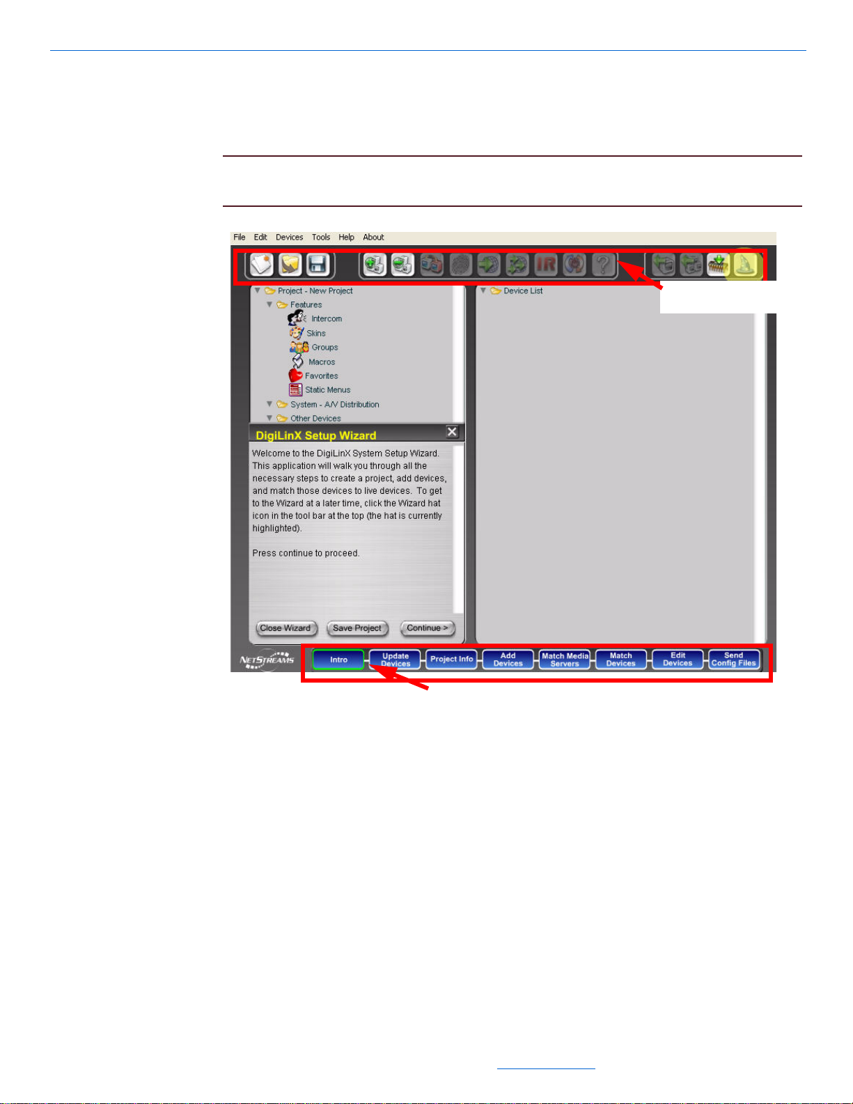
Interface
You can set up devices using DigiLinX Dealer Setup either manually or with the
Wizard.
NOTE: This manual uses the Wizard as the basis for installation. See Figure 1-1 for the
DigiLinX Dealer Setup interface.
1-4
Figure 1-1 DigiLinX Dealer Setup Interface
Buttons
There are two rows of buttons available from the DigiLinX Dealer Setup interface. The
ones at the top are available for use when you are not using the DigiLinX Dealer Setup
Wizard to configure your system. The bottom row buttons are only visible when you
are using the Wizard.
Table 1-1 defines the use of each button.
All specifications subject to change without notification. All rights reserved. Copyright © 2008 NetStreams
Main +1 512.977-9393 / fax +1 512.977.9398 / Toll Free Technical Support +1 866-353-3496
3600 W. Parmer Lane, Suite 100; Austin, TX 78727 / www.netstreams.com.
Page 13
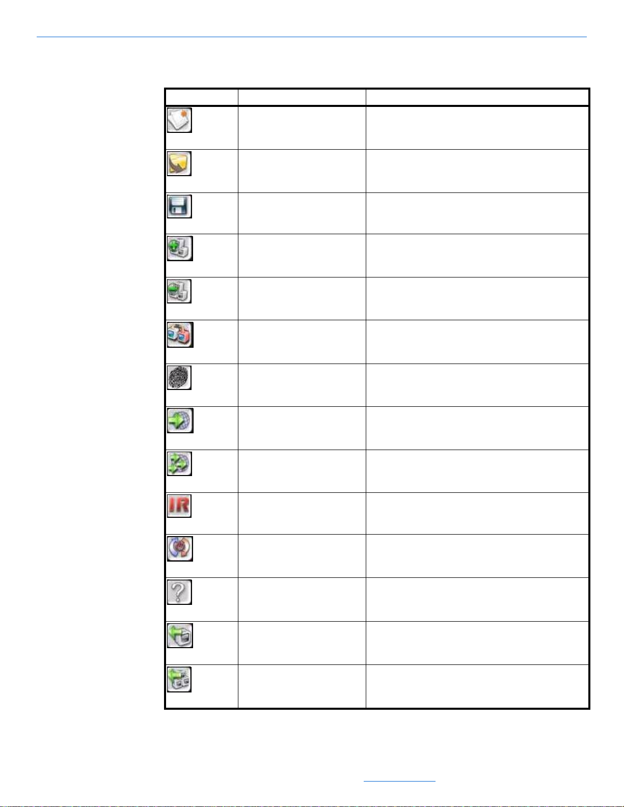
Table 1-1
Buttons
Button Means Function
New Project Creates a new project.
Open Project Opens a previously-saved project.
Save Project Saves the current project to a file.
Add Device Lets you add another device to the current project.
Remove Device Lets you remove a device from the current project.
Match Device Lets you match the physical device by MAC (machine
addressable code).
Introduction
ID Devices Lets you identify and match physical devices with the project.
Send Configuration to Device Sends information from the project file to the device.
Send Configuration to Multiple
Devices
IR Tools Configures IR to work with the DigiLinX system.
Restart Device Lets you restart the selected device.
About Device Displays important information about the device.
Import Device Troubleshooting tool that allows you to take a device that
Sends information from the device to multiple devices.
physically exists on the network and import its configuration.
Import System Troubleshooting tool that allows you to take all devices that
physically exist on the network and import their configuration.
All specifications subject to change without notification. All rights reserved. Copyright © 2008 NetStreams
Main +1 512.977-9393 / fax +1 512.977.9398 / Toll Free Technical Support +1 866-353-3496
3600 W. Parmer Lane, Suite 100; Austin, TX 78727 / www.netstreams.com.
1-5
Page 14
DigiLinX Dealer Setup Version 2.35.00
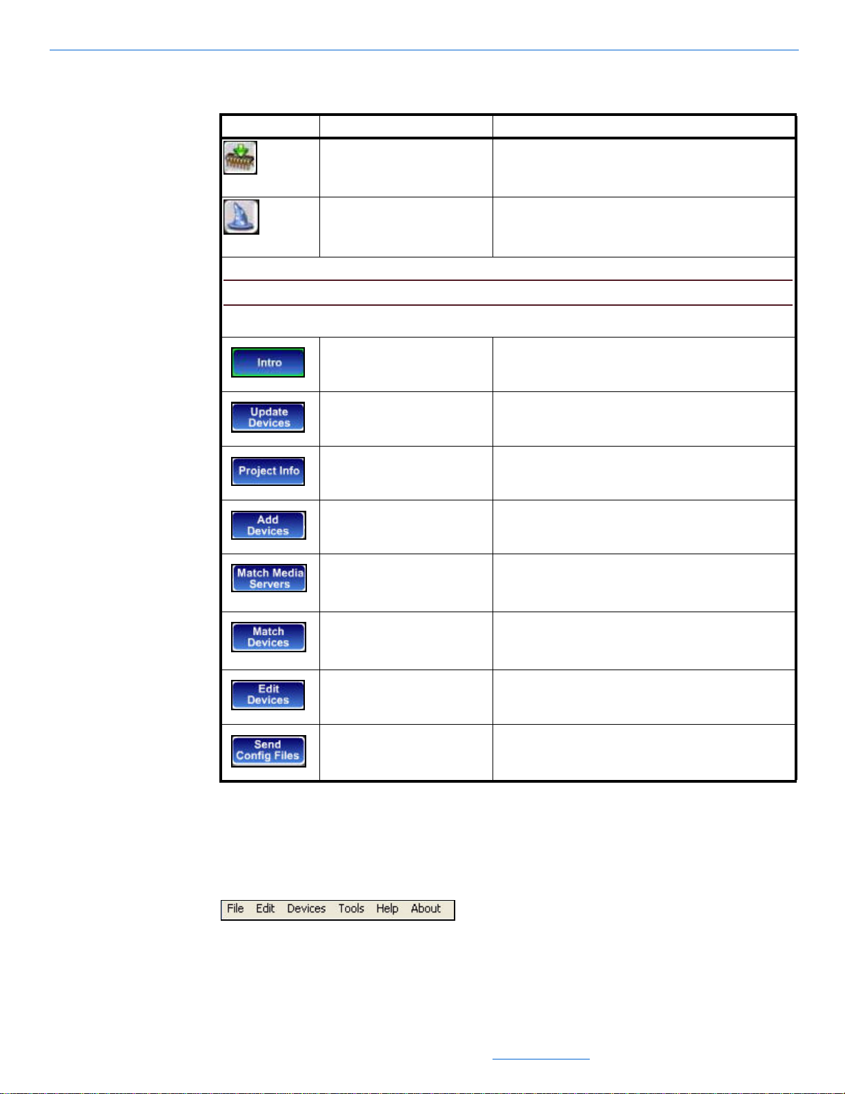
Button Means Function
NOTE:The following buttons are only available when the DigiLinX Dealer Setup Wizard is running.
Table 1-1
Buttons
Update Devices Shows you a current listing of all devices connected to the
system and their current firmware version.
Setup Wizard Returns you to the DigiLinX Dealer Setup Wizard.
Intro Introduction to the DigiLinX system.
Update Devices Shows you a current listing of all devices connected to the
system and their current firmware version.
Project Info Lets you enter unique network-specific information for this
project.
Add Devices Lets you add another device to the current project.
Match Media Servers Lets you match a media server created in the project to the
Match Devices Lets you associate a device (such as MediaLinX,
Edit Devices Lets you edit the configuration information in various ways
Send Config Files Takes all the information you’ve defined up to this point and
physical device. This is done to ensure that the IP address of
the media server matches the IP address configured in the
project.
SpeakerLinX, and so on) in a project with the physical device.
This is how Dealer Setup knows which configuration to send
to which device.
depending on the device selected.
uploads it to the system.
Areas of the Interface Screen
There are four areas of the interface screen. These include:
1-6
Menu Bar. The menu bar allows you to select operations from the File, Edit,
Devices, Tools, Help, or About menus (see Figure 1-2)
Figure 1-2 Menu Bar
Project area - displays project hardware as you create it (see Figure 1-3)
All specifications subject to change without notification. All rights reserved. Copyright © 2008 NetStreams
Main +1 512.977-9393 / fax +1 512.977.9398 / Toll Free Technical Support +1 866-353-3496
3600 W. Parmer Lane, Suite 100; Austin, TX 78727 / www.netstreams.com.
Page 15
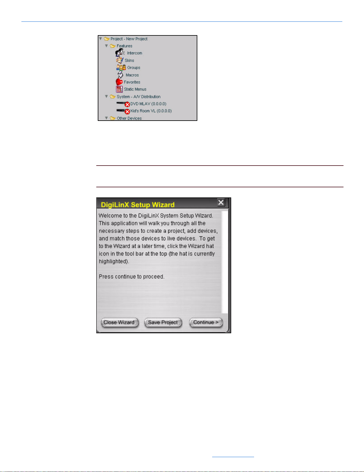
Introduction
Figure 1-3 Project area
Wizard area - displays information about the current process being performed
using the Wizard (see Figure 1-4). Contains buttons to close the Wizard, save your
project, or continue to the next Wizard operation
NOTE: If you hold the left mouse button down over the title bar of this window, you
can move the Wizard area to anywhere on your DigiLinX screen.
Figure 1-4 Wizard area
All specifications subject to change without notification. All rights reserved. Copyright © 2008 NetStreams
Main +1 512.977-9393 / fax +1 512.977.9398 / Toll Free Technical Support +1 866-353-3496
3600 W. Parmer Lane, Suite 100; Austin, TX 78727 / www.netstreams.com.
1-7
Page 16
DigiLinX Dealer Setup Version 2.35.00
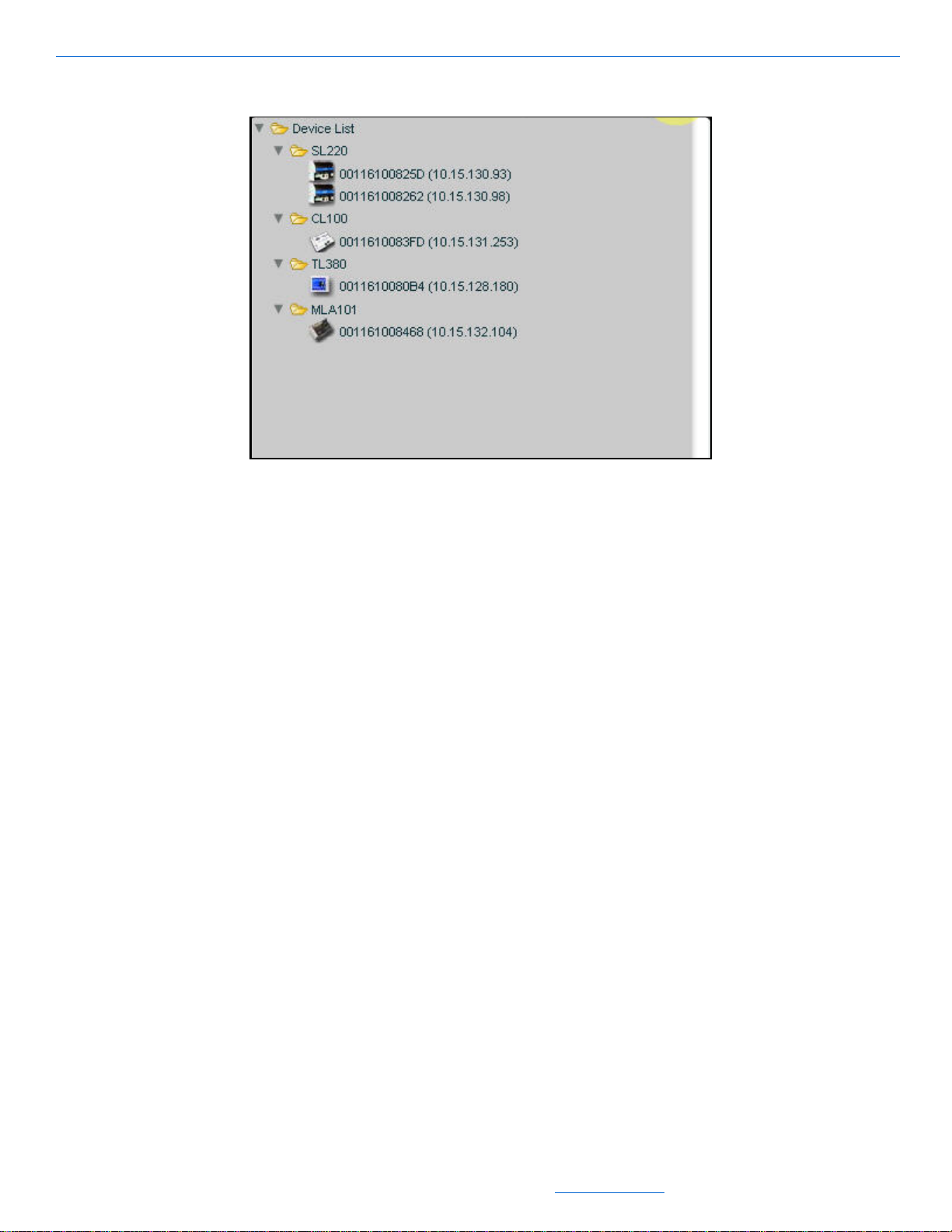
Device List - lists the physical devices attached to your system (see Figure 1-5).
Figure 1-5 Device list
1-8
All specifications subject to change without notification. All rights reserved. Copyright © 2008 NetStreams
Main +1 512.977-9393 / fax +1 512.977.9398 / Toll Free Technical Support +1 866-353-3496
3600 W. Parmer Lane, Suite 100; Austin, TX 78727 / www.netstreams.com.
Page 17

Installing and Running DigiLinX Dealer Setup
Chapter
2
Installing and Running DigiLinX Dealer Setup
Installing DigiLinX Dealer Setup Version 2.3
Before you can run the DigiLinX Dealer Setup program, you must install and
configure the software.
1. Close any open applications.
2. From your PC, open Internet Explorer.
3. Go to http://www.netstreams.com.
4. From the Dealer Login area in the lower left-hand corner of the screen, enter your
username and password and select Login.
A Dealer information page appears.
5. Select Dealer Documents.
A list of NetStreams documents and application categories appears.
6. Scroll to the DigiLinX Tools section.
7. Click the + (plus) sign next to DigiLinX Tools and a list of tools will appear.
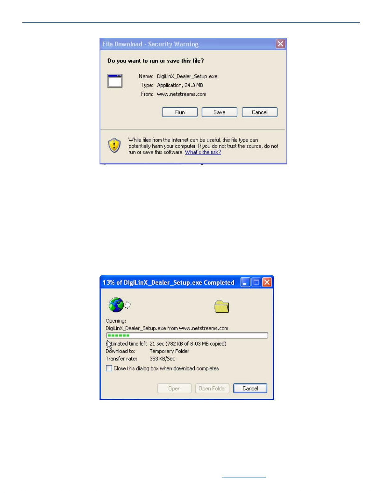
8. Click the DigiLinX Dealer Setup Program Version 2.3.
You are asked if you want to run or save the DigiLinX Dealer Setup program (see
Figure 2-1).
All specifications subject to change without notification. All rights reserved. Copyright © 2008 NetStreams
Main +1 512.977-9393 / fax +1 512.977.9398 / Toll Free Technical Support +1 866-353-3496
3600 W. Parmer Lane, Suite 100; Austin, TX 78727 / www.netstreams.com.
2-1
Page 18
DigiLinX Dealer Setup Version 2.35.00
Figure 2-1 Application prompt
Select Save.
9.
You are prompted to save the file to your computer.
10. Browse to the folder where you’d like to save the file.
11. Select Save As... .
The file saves to the indicated location on your hard drive.
12. Using Windows Explorer, navigate to the file you just saved on your computer.
13. Double-click the file to run it.
The setup program opens (see Figure 2-2).
Figure 2-2 Application opens
2-2
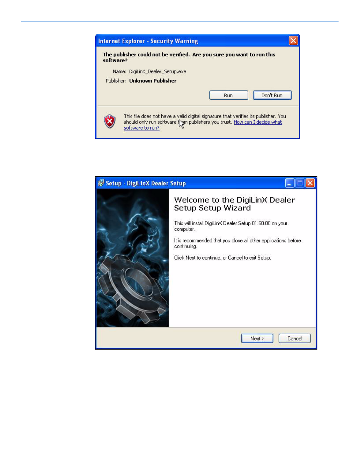
You may be prompted that the publisher could not be verified (see Figure 2-3).
All specifications subject to change without notification. All rights reserved. Copyright © 2008 NetStreams
Main +1 512.977-9393 / fax +1 512.977.9398 / Toll Free Technical Support +1 866-353-3496
3600 W. Parmer Lane, Suite 100; Austin, TX 78727 / www.netstreams.com.
Page 19
Installing and Running DigiLinX Dealer Setup
Figure 2-3 Publisher verification
Select Run.
14.
The DigiLinX Dealer Setup Wizard Welcome window displays (see Figure 2-4).
Figure 2-4 Welcome window
Select Next.
15.
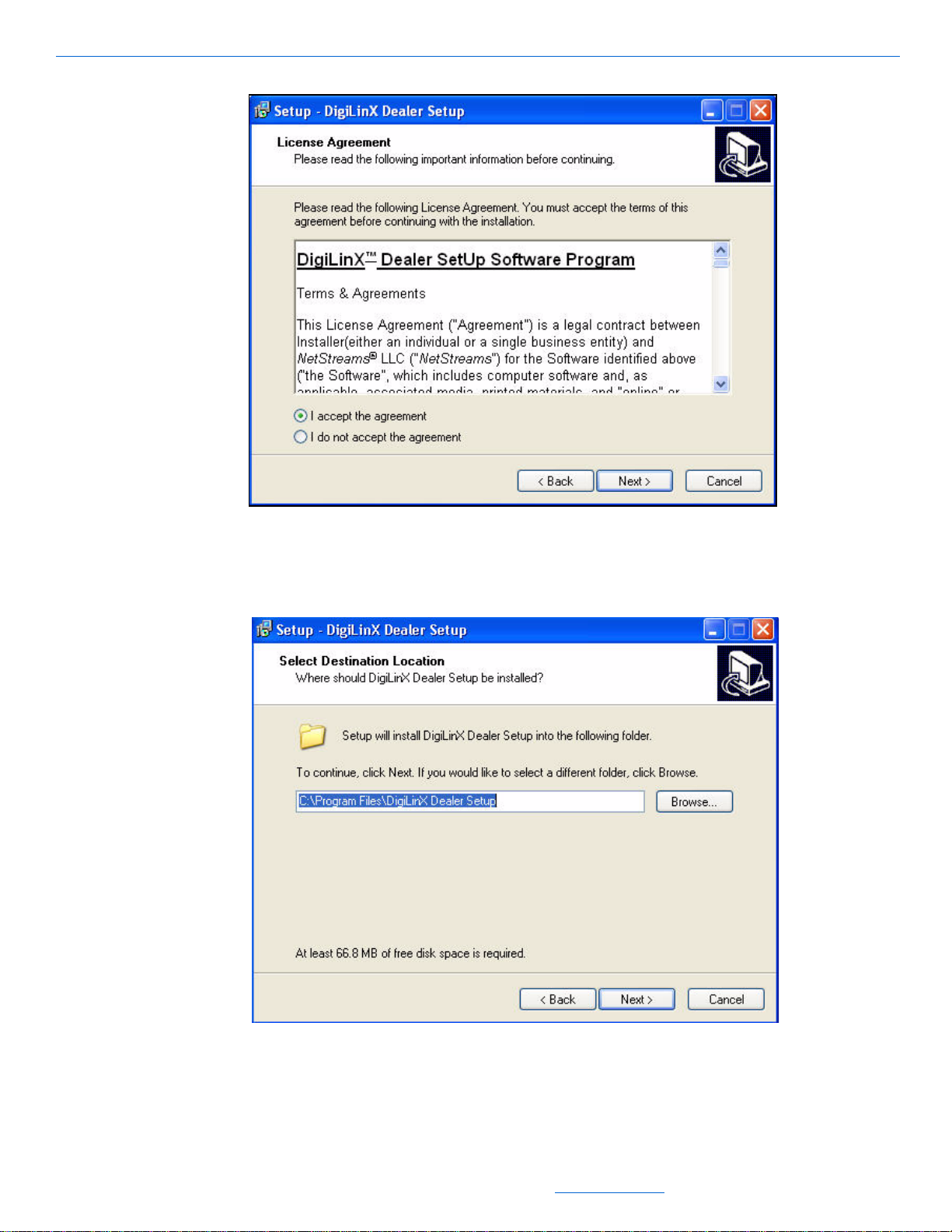
A License Agreement displays (see Figure 2-5).
All specifications subject to change without notification. All rights reserved. Copyright © 2008 NetStreams
Main +1 512.977-9393 / fax +1 512.977.9398 / Toll Free Technical Support +1 866-353-3496
3600 W. Parmer Lane, Suite 100; Austin, TX 78727 / www.netstreams.com.
2-3
Page 20
DigiLinX Dealer Setup Version 2.35.00
Figure 2-5 License Agreement
After reading the agreement, select I accept and then select Next.
16.
You are prompted to select a location for the file to download (see Figure 2-6).
2-4
Figure 2-6 Destination prompt
Keep the default entry and select Next.
17.
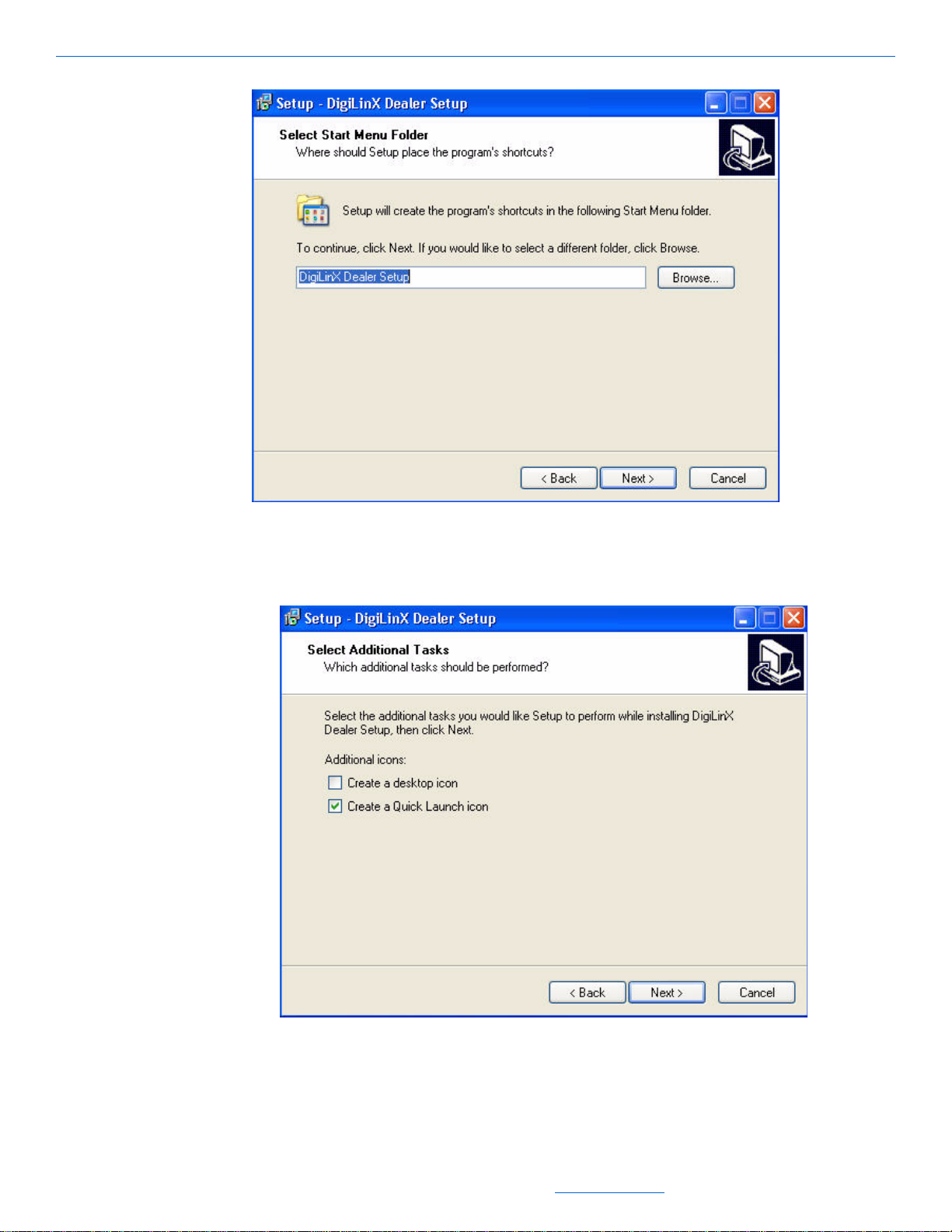
You are asked where the application shortcut should be placed (see Figure 2-7).
All specifications subject to change without notification. All rights reserved. Copyright © 2008 NetStreams
Main +1 512.977-9393 / fax +1 512.977.9398 / Toll Free Technical Support +1 866-353-3496
3600 W. Parmer Lane, Suite 100; Austin, TX 78727 / www.netstreams.com.
Page 21
Installing and Running DigiLinX Dealer Setup
Figure 2-7 Shortcut destination prompt
Keep the default entry and select Next.
18.
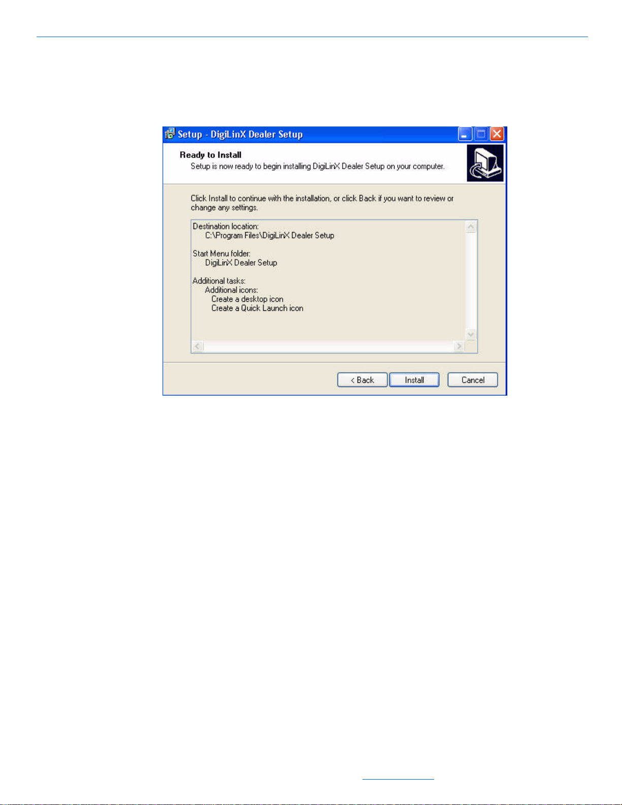
You are asked where you want additional application icons placed (see Figure 2-8).
Figure 2-8 Additional icon placement
Select:
19.
Create a desktop icon if you want to place an icon on your computer’s desktop
All specifications subject to change without notification. All rights reserved. Copyright © 2008 NetStreams
Main +1 512.977-9393 / fax +1 512.977.9398 / Toll Free Technical Support +1 866-353-3496
3600 W. Parmer Lane, Suite 100; Austin, TX 78727 / www.netstreams.com.
2-5
Page 22
DigiLinX Dealer Setup Version 2.35.00
Create a Quick Launch icon if you want to place an icon in your computer’s
Quick Launch tray.
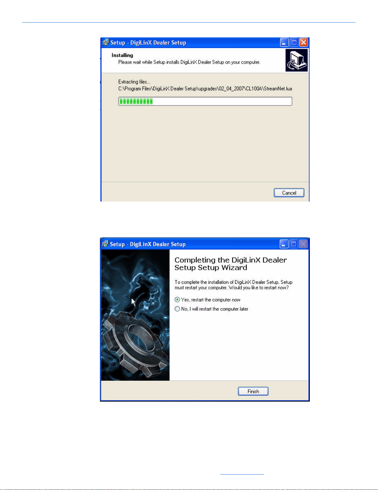
20. Select Next.
You are prompted that the application is ready to install (see Figure 2-9).
Figure 2-9 Ready to install prompt
Select Install.
21.
The application begins installation (see Figure 2-10).
2-6
All specifications subject to change without notification. All rights reserved. Copyright © 2008 NetStreams
Main +1 512.977-9393 / fax +1 512.977.9398 / Toll Free Technical Support +1 866-353-3496
3600 W. Parmer Lane, Suite 100; Austin, TX 78727 / www.netstreams.com.
Page 23
Installing and Running DigiLinX Dealer Setup
Figure 2-10 Application installation window
When the application finishes installing, you are prompted to restart (see
Figure 2-11).
Figure 2-11 Setup Wizard complete
Select Yes, restart the computer now and then select Finish.
22.
Your computer restarts and the installation is complete.
All specifications subject to change without notification. All rights reserved. Copyright © 2008 NetStreams
Main +1 512.977-9393 / fax +1 512.977.9398 / Toll Free Technical Support +1 866-353-3496
3600 W. Parmer Lane, Suite 100; Austin, TX 78727 / www.netstreams.com.
2-7
Page 24
DigiLinX Dealer Setup Version 2.35.00
Configuring the Network Interface Card (NIC) in Windows
Dealer Setup requires a wired connection to the switch to configure a system. To
prevent Dealer Setup from inadvertently using a wireless connection, you must
temporarily disable the wireless NIC. To set this configuration, complete steps in the
following section.
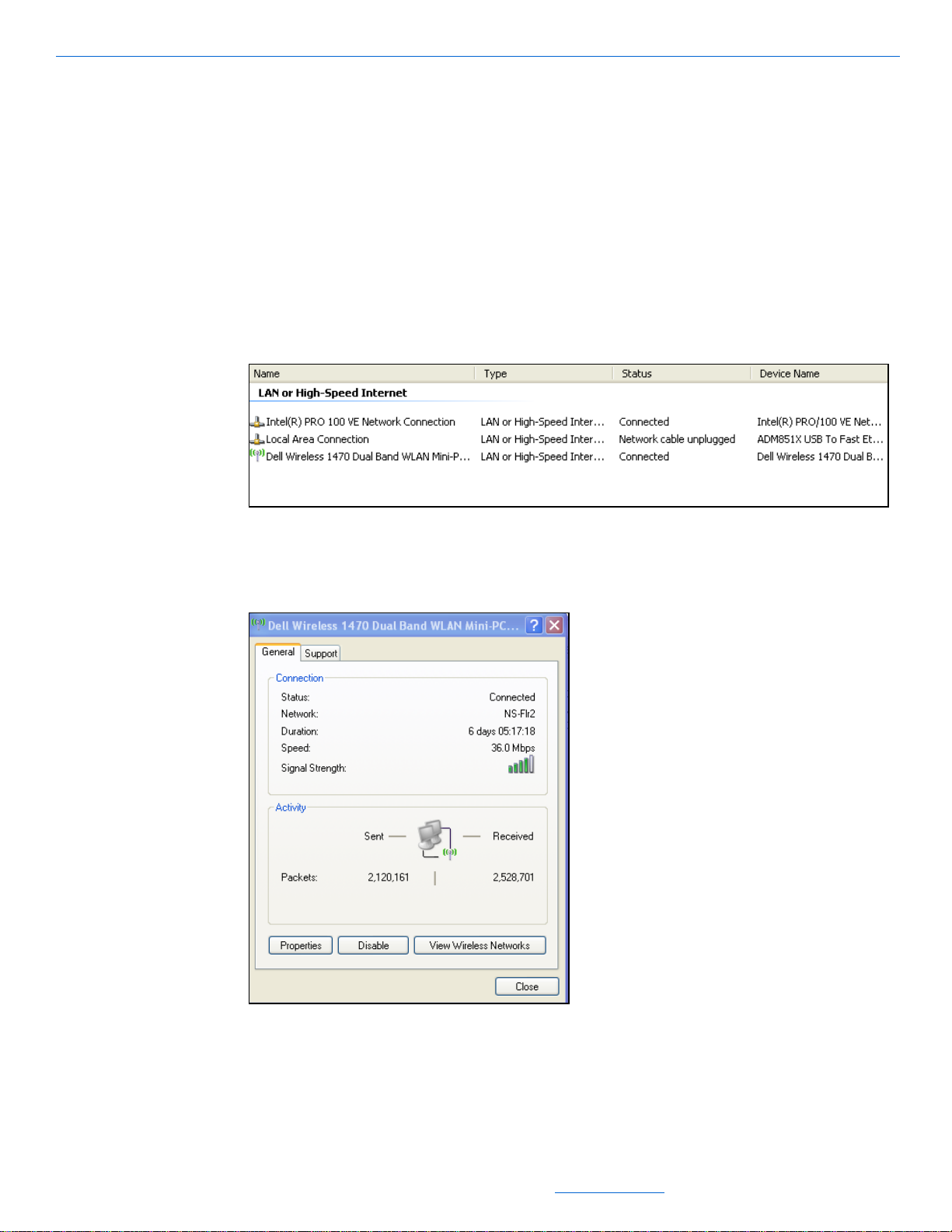
Disable the Wireless NIC
1. From your Windows S t art menu, select Start>Settings>Control Panel>Network
Connections.
The Network Connections screen displays (see Figure 2-12).
Figure 2-12 Network Connections screen
Double-click on the wireless NIC (if any are present).
2.
A Properties window displays (see Figure 2-14).
2-8
Figure 2-13 Properties window
All specifications subject to change without notification. All rights reserved. Copyright © 2008 NetStreams
Main +1 512.977-9393 / fax +1 512.977.9398 / Toll Free Technical Support +1 866-353-3496
3600 W. Parmer Lane, Suite 100; Austin, TX 78727 / www.netstreams.com.
Page 25
Installing and Running DigiLinX Dealer Setup
3. Select Disable and close the window.
Setting the IP Address
The NIC used to connect to the DigiLinX system needs the IP address set to dynamic.
To make this change, complete the following steps:
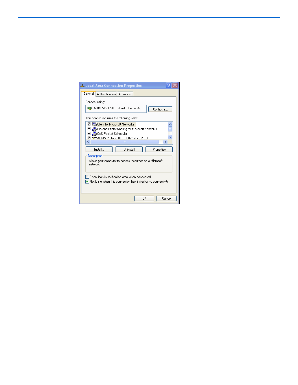
1. Right-click the NIC you are configuring and select Properties.
A Properties window displays (see Figure 2-14).
Figure 2-14 Properties window
In the “This connection uses the following items” area, scroll until Internet
2.
Protocol (TCP/IP) displays.
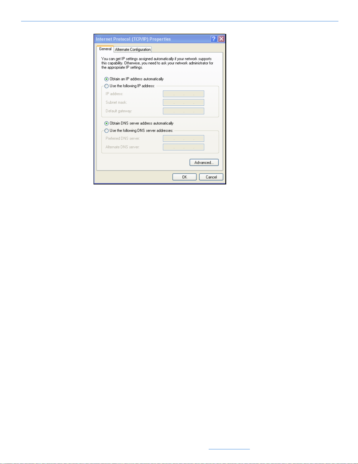
3. Double-click on Internet Protocol (TCP/IP).
The TCP/IP Properties window displays (see Figure 2-15).
All specifications subject to change without notification. All rights reserved. Copyright © 2008 NetStreams
Main +1 512.977-9393 / fax +1 512.977.9398 / Toll Free Technical Support +1 866-353-3496
3600 W. Parmer Lane, Suite 100; Austin, TX 78727 / www.netstreams.com.
2-9
Page 26
DigiLinX Dealer Setup Version 2.35.00
Figure 2-15 TCP/IP Properties window
Ensure that Obtain an IP address automatically is checked.
4.
5. Select OK.
You are returned to the Properties window.
6. Select OK.
Your changes are applied.
Running DigiLinX Dealer Setup
To start the DigiLinX Dealer Setup program, complete the following steps:
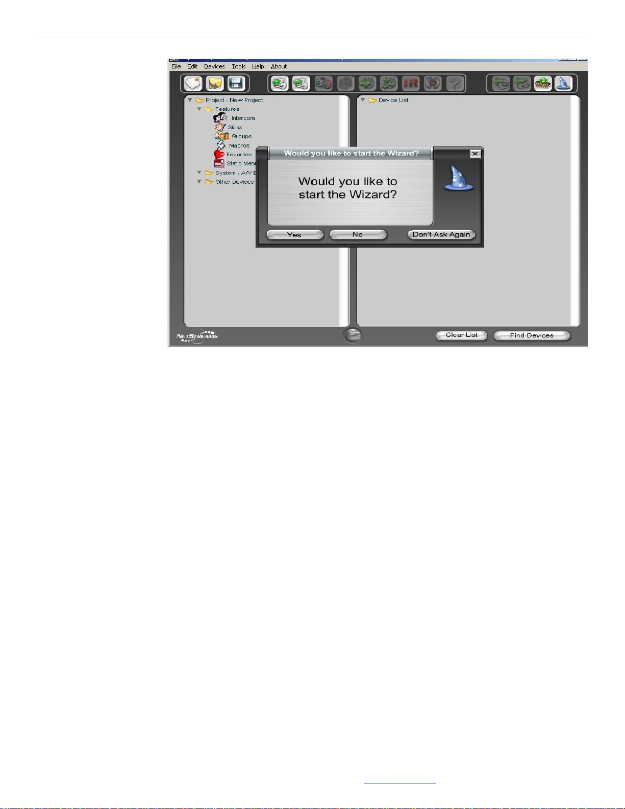
1. Select Start>All Programs>DigiLinX Dealer Setup>DigiLinX Dealer Setup (or
double-click the Dealer Setup desktop icon).
The DigiLinX Dealer Setup application window displays (see Figure 2-16). You
are prompted to start the Wizard.
2-10
All specifications subject to change without notification. All rights reserved. Copyright © 2008 NetStreams
Main +1 512.977-9393 / fax +1 512.977.9398 / Toll Free Technical Support +1 866-353-3496
3600 W. Parmer Lane, Suite 100; Austin, TX 78727 / www.netstreams.com.
Page 27
Installing and Running DigiLinX Dealer Setup
Figure 2-16 Application window
Select No.
2.
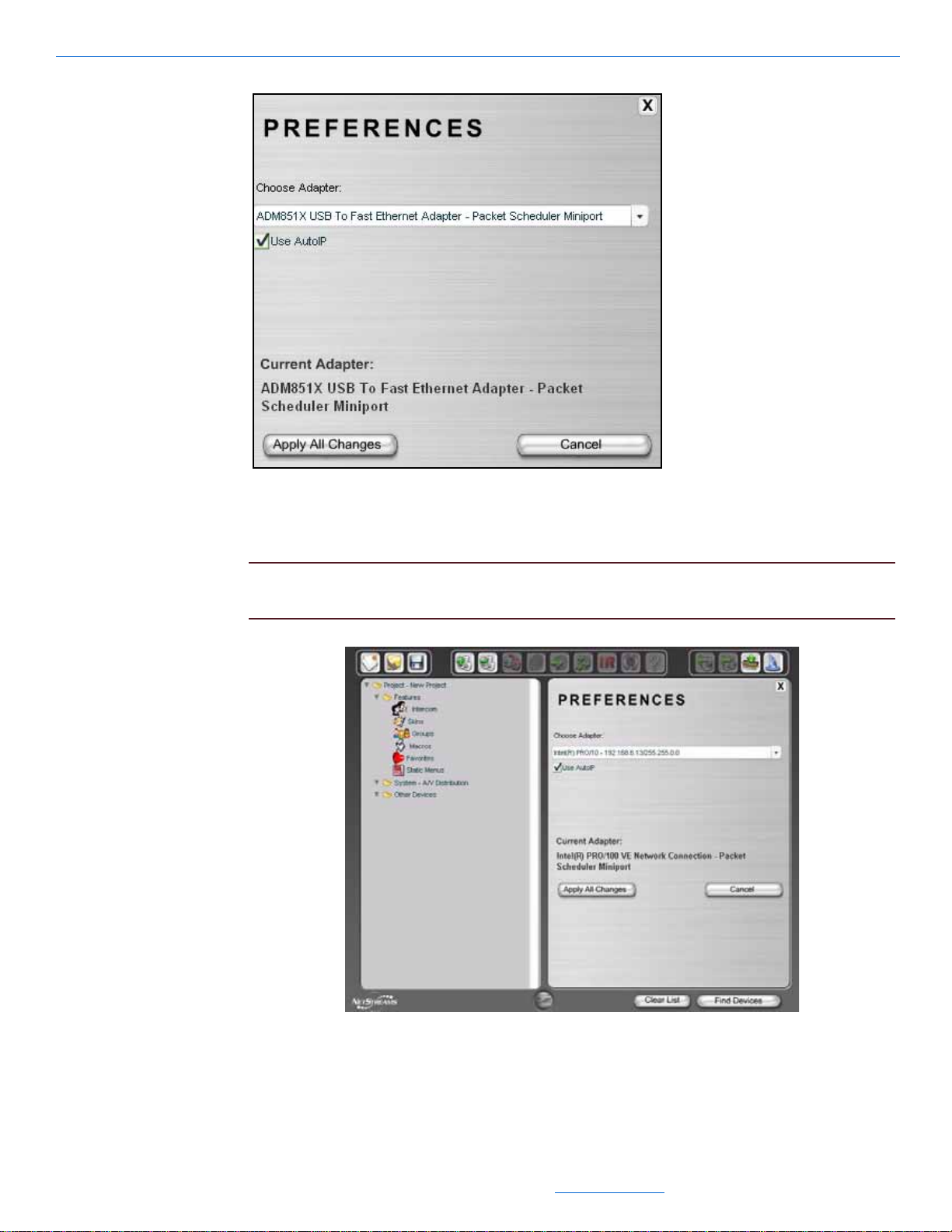
Configuring the NIC in Dealer Setup
For systems that have multiple NICs, you can tell Dealer Setup which is being used to
interface with DigiLinX. To identify which card to use, complete the following steps:
1. From the main window of Dealer Setup, select Edit >Preferences.
The Preferences window displays (see Figure 2-17).
All specifications subject to change without notification. All rights reserved. Copyright © 2008 NetStreams
Main +1 512.977-9393 / fax +1 512.977.9398 / Toll Free Technical Support +1 866-353-3496
3600 W. Parmer Lane, Suite 100; Austin, TX 78727 / www.netstreams.com.
2-11
Page 28
DigiLinX Dealer Setup Version 2.35.00
Figure 2-17 Preferences window
From the Choose Adapter dropdown list, select the specific NIC you are using to
2.
create DigiLinX projects (see Figure 2-18).
IMPORTANT! Remember, any wireless NIC should be disabled when using Dealer
Setup. Also, do not make the selection “Use all NIC Cards.”
2-12
Figure 2-18 Selecting a NIC from the dropdown list
All specifications subject to change without notification. All rights reserved. Copyright © 2008 NetStreams
Main +1 512.977-9393 / fax +1 512.977.9398 / Toll Free Technical Support +1 866-353-3496
3600 W. Parmer Lane, Suite 100; Austin, TX 78727 / www.netstreams.com.
Page 29
Installing and Running DigiLinX Dealer Setup
3. Select Apply All Changes.
4. Exit Dealer Setup.
5. Re-open Dealer Setup.
The DigiLinX Dealer Setup application window displays (see Figure 2-16). You
are prompted to start the Wizard.
6. Select Yes.
You are ready to begin creating your project. Before you begin project creation,
review the process for determining an IP address on the DigiLinX network.
IP and DigiLinX Tutorial
DigiLinX communicates with control devices, amplifiers, audio sources and
computers using Transmission Control Protocol/Internet Protocol. TCP/IP is a means
of sending and receiving information on a computer network. For example, with
DigiLinX you can take a song from a CD player and send it via TCP/IP to an amplifier.
This is an oversimplification of the process. IP is a much more complicated process,
but how it applies to DigiLinX is not.
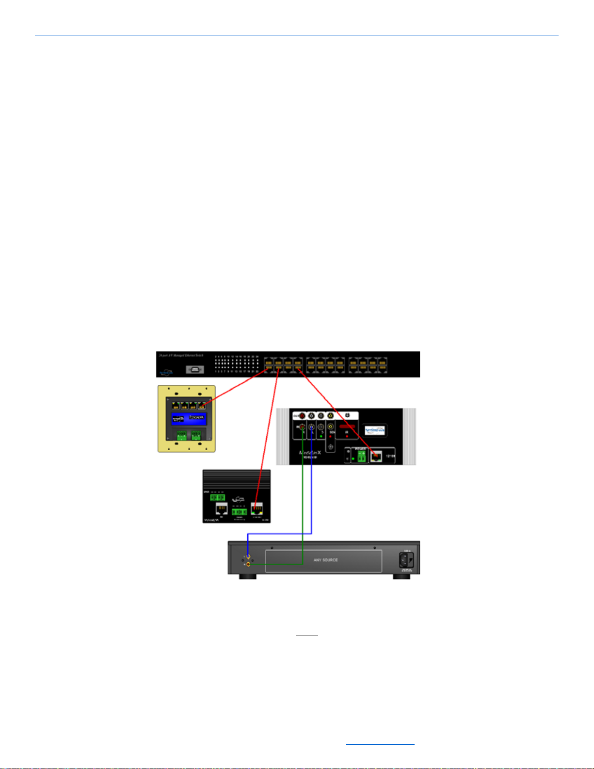
In Figure 2-19, you have control devices (TouchLinX), legacy source devices
(MediaLinX), and output devices (SpeakerLinX) connected together. For these devices
to communicate using TCP/IP each device must have a unique identifier or IP address.
Figure 2-19 DigiLinX Network Diagram
IP Address and the Subnet Mask
On a network, all the devices must use the same IP address scheme so that they know
where to send information. This scheme is determined by the subnet mask (for
example, 255.255.255.0) and the IP address (for example, 192.168.1.110). The IP
address has four octets that can be divided into two sections that determine the network
and the device. You can tell which octets in an address are the network identifiers by
All specifications subject to change without notification. All rights reserved. Copyright © 2008 NetStreams
Main +1 512.977-9393 / fax +1 512.977.9398 / Toll Free Technical Support +1 866-353-3496
3600 W. Parmer Lane, Suite 100; Austin, TX 78727 / www.netstreams.com.
2-13
Page 30

DigiLinX Dealer Setup Version 2.35.00
referring to the subnet mask. In the subnet you also have four octets containing either
the number 255 or the number 0. This denotes which octet in the IP address is part of
the network number. For example:
If the IP address is 10.15.20.13 and the subnet is 255.0.0.0 Then this device is on
the 10 network and it is device 15.20.13
If the IP address is 10.15.20.13 and the subnet is 255.255.0.0 Then that device is
on the 10.15 network and it is device 20.13
If the IP address is 10.15.20.13 and the subnet is 255.255.255.0 Then that device is
on the 10.15.20 network and it is device 13
If the IP address is 192.168.1.100 and the subnet is 255.255.255.0 Then that
device is on the 192.168.1 network and it is device 100.
For devices to communicate with each other they must all have the same network
number but have unique device numbers. On a DigiLinX network, devices have a
subnet mask of 255.0.0.0 and an IP address of 10.x.x.x. This means that all devices on
a DigiLinX network must have an IP address starting with 10 and the remaining
numbers must be unique. Table 2-1 shows three devices and whether they can
communicate with each other.
Table 2-1
IP Addressing Examples
DEVICE 1 DEVICE 2
IP ADDRESS Subnet Mask IP ADDRESS
10.15.1.110 255.0.0.0 10.16.5.25 255.0.0.0 Yes they can talk.
10.15.1.110 255.255.0.0 10.16.5.25 255.255.0.0 No, the subnet makes the first 2
10.15.1.110 255.255.255.0 192.168.1.110 255.255.255.0 No, the network numbers are not
Subnet
Mask
Results
octets the network number and in
this example the first two octets
are not the same so they are not
part of the same system.
the same. The subnet requires
that the first three octets be the
same. These are clearly not.
This explanation of TCP/IP explains key networking concepts of DigiLinX. The next
section explains how a DigiLinX network is assembled.
Building a DigiLinX IP Network
2-14
By default, DigiLinX automatically assigns IP addresses using a NetStreams AutoIP
process (not to be confused with Dynamic Host Configuration Protocol - DHCP). This
allows DigiLinX to function as a standalone system. Figure 2-20 is a simple DigiLinX
network with sample IP addresses:
All specifications subject to change without notification. All rights reserved. Copyright © 2008 NetStreams
Main +1 512.977-9393 / fax +1 512.977.9398 / Toll Free Technical Support +1 866-353-3496
3600 W. Parmer Lane, Suite 100; Austin, TX 78727 / www.netstreams.com.
Page 31

Installing and Running DigiLinX Dealer Setup
TouchLinX
10.15.30.25
255.0.0.0
MediaLinX
10.15.30.26
255.0.0.0
SpeakerLinX
10.15.11.29
255.0.0.0
Figure 2-20 Building a DigiLinX IP Network (1 of 5)
The IP addresses in Figure 2-20 all work in the same IP range (as defined by the
subnet). Given these settings, this is a working DigiLinX system. However, it’s not a
practical one. There are no sources or speakers, and it only has one room. Figure 2-21
is a somewhat more realistic network diagram with IP addresses that are consistent
with a default DigiLinX system.
Notice that they all work in the same IP range and a PC (for configuring the system)
also exists on the network. When DigiLinX Dealer Setup is started on a PC, it
determines what IP address range to use, and will automatically assign itself a valid IP
address. You do not need to make an address change to your PC when you use the
DigiLinX Dealer Setup program; however, you must assign a network card (see
Configuring the NIC in Dealer Setup on page 2-11).
DigiLinX requires very little knowledge of IP, but adding non-DigiLinX devices is a
little more complex. These devices can’t configure valid IP addresses by themselves.
You must create and assign addresses manually. In Figure 2-21, a digital media server
and an IP camera have been added. The IP address on the media server and IP camera
must be changed so that they use a valid address that follows the correct IP addressing
scheme.
2-15
All specifications subject to change without notification. All rights reserved. Copyright © 2008 NetStreams
Main +1 512.977-9393 / fax +1 512.977.9398 / Toll Free Technical Support +1 866-353-3496
3600 W. Parmer Lane, Suite 100; Austin, TX 78727 / www.netstreams.com.
Page 32

DigiLinX Dealer Setup Version 2.35.00
Laptop
10.15.3.5
255.0.0.0
Laptop
10.15.3.5
255.0.0.0
Media Server
10.15.100.110
255.0.0.0
SpeakerLinX
10.15.11.29
255.0.0.0
Laptop
10.15.3.5
255.0.0.0
SpeakerLinX
10.15.33.5
255.0.0.0
IP Camera
10.15.100.225
255.0.0.0
TouchLinX
10.15.30.25
255.0.0.0
SpeakerLinX
10.15.18.21
255.0.0.0
MediaLinX
10.15.30.26
255.0.0.0
Figure 2-21 Building a DigiLinX IP Network (2 of 5)
All of these DigiLinX examples are based on using DigiLinX to assign IP addresses
using factory defaults. However, in many installations the customer wants to integrate
DigiLinX into the home network. This level of integration requires the installer to
change the default DigiLinX IP address scheme to one that matches the home
network’s IP address scheme. See Figure 2-22.
2-16
All specifications subject to change without notification. All rights reserved. Copyright © 2008 NetStreams
Main +1 512.977-9393 / fax +1 512.977.9398 / Toll Free Technical Support +1 866-353-3496
3600 W. Parmer Lane, Suite 100; Austin, TX 78727 / www.netstreams.com.
Page 33

Laptop
10.153.5
255.0.0.0
MediaLinX
10.15.30.26
255.0.0.0
SpeakerLinX
10.15.18.21
255.0.0.0
SpeakerLinX
10.15.11.29
255.0.0.0
SpeakerLinX
10.15.33.5
255.0.0.0
PC
192.168.1.3
255.255.255.0
PC
192.168.1.4
255.255.255.0
Media Server
10.15.100.110
255.0.0.0
10.15199.225
255.0.0.0
TouchLinX
10.15.30.25
255.0.0.0
Router/
Switch
192.168.1.1
255.255.255.0
Installing and Running DigiLinX Dealer Setup
IP Camera
Figure 2-22 Building a DigiLinX IP Network (3 of 5)
Notice that the address for the home network does not match the IP address scheme for the DigiLinX
network. Left this way, the DigiLinX network would work independently of the Home network, but
the home network would not be able to control the DigiLinX system.
Configuring the Home Network and DigiLinX
To change the IP range for DigiLinX so that it matches the home network’s IP address range, refer to
Figure 2-22. In this example, the home network has a subnet of 255.255.255.0. This means that all
addresses on the home network must use the same numbers in the first three octets. In this case, all IP
address must start with 192.168.1 and the final octet must be unique. To make DigiLinX work with
this network all devices on the DigiLinX network must also start with 192.168.1 and the fourth octet
must also be unique.
To change the system IP address range and subnet range, complete the following steps:
1. With the system live, highlight System-A/V Distribution from Dealer Setup.
2. Select Advanced Options.
System information displays (see Figure 2-23).
All specifications subject to change without notification. All rights reserved. Copyright © 2008 NetStreams
Main +1 512.977-9393 / fax +1 512.977.9398 / Toll Free Technical Support +1 866-353-3496
3600 W. Parmer Lane, Suite 100; Austin, TX 78727 / www.netstreams.com.
2-17
Page 34

DigiLinX Dealer Setup Version 2.35.00
Figure 2-23 Building a DigiLinX IP Network (4 of 5)
Enter the appropriate address range for the system. In this case, it’s 192.168.1.20
3.
to 192.168.1.100 with a system subnet mask of 255.255.255.0.
4. Select Apply Changes.
The IP address is applied across the network (see Figure 2-24).
IP Camera
2-18
All specifications subject to change without notification. All rights reserved. Copyright © 2008 NetStreams
Main +1 512.977-9393 / fax +1 512.977.9398 / Toll Free Technical Support +1 866-353-3496
3600 W. Parmer Lane, Suite 100; Austin, TX 78727 / www.netstreams.com.
Page 35

Installing and Running DigiLinX Dealer Setup
192.168.1.225
255.255.255.0
Laptop
192.168.1.115
255.255.255.0
MediaLinX
198.168.1.20
255.255.255.0
SpeakerLinX
192.168.1.21
255.255.255.0
SpeakerLinX
192.168.1.29
SpeakerLinX
198.162.1.35
255.255.255,0
PC
192.168.1.4
255.255.255.0
PC
192.168.1.3
255.255.255.0
Media Server
192.168.1.110
255.255.255.0
Router/Switch
192.168.1.1
255.255.255.0
IP Camera
255.255.255.0
Figure 2-24 Building a DigiLinX IP Network (5 of 5)
NOTE: Some devices on the DigiLinX network may require access to the Internet like
the digital media server. These devices require additional IP settings like the
Gateway IP and DNS address on the digital media server. For more details on
configuring DigiLinX to work on the home network refer to the Application
Note titled: DigiLinX Home PC Network Integration from the Dealer section of
the NetStreams website, www.netstreams.com).
All specifications subject to change without notification. All rights reserved. Copyright © 2008 NetStreams
Main +1 512.977-9393 / fax +1 512.977.9398 / Toll Free Technical Support +1 866-353-3496
3600 W. Parmer Lane, Suite 100; Austin, TX 78727 / www.netstreams.com.
2-19
Page 36

DigiLinX Dealer Setup Version 2.35.00
2-20
All specifications subject to change without notification. All rights reserved. Copyright © 2008 NetStreams
Main +1 512.977-9393 / fax +1 512.977.9398 / Toll Free Technical Support +1 866-353-3496
3600 W. Parmer Lane, Suite 100; Austin, TX 78727 / www.netstreams.com.
Page 37

Creating and Saving Projects
Chapter
3
Creating and Saving Projects
A project is a file (saved with an extension of .nsp) that contains all of the settings for
each of the devices in a system. A dealer can use the DigiLinX Dealer Setup program
to create a project that is specific to each home that has a NetStreams system.
For example, you can name a project “John Doe” and transfer it to the home system
after the hardware has been installed. You can create a project while you're connected
to a DigiLinX system or in the comfort of your own office.
NOTE: Procedures vary slightly depending on whether or not you are connected to the
DigiLinX network at the time you create the project. Following the Setup
Wizard is the best way to prevent errors in project creation.
Creating a New Project
This section covers the processes involved in creating a new DigiLinX project.
Discovering Devices
To begin a project while connected to the DigiLinX network, the software must locate
all attached devices. To discover devices, complete the following steps:
1. From the Dealer Setup Wizard, select Continue from the lower left-hand corner of
the window.
The Update StreamNet Devices screen displays if you are connected to the
DigiLinX network (see Figure 3-1). This screen locates all devices connected to
the network.
All specifications subject to change without notification. All rights reserved. Copyright © 2008 NetStreams
Main +1 512.977-9393 / fax +1 512.977.9398 / Toll Free Technical Support +1 866-353-3496
3600 W. Parmer Lane, Suite 100; Austin, TX 78727 / www.netstreams.com.
3-1
Page 38

DigiLinX Dealer Setup Version 2.35.00
Tip: You may not want to
check “Include XM Station Art”
every time you update
devices. This feature updates
metadata for sources attached
to a MediaLinX and may take
quite a bit of time to load. To
skip the update of XM Station
Art, uncheck the box next to
“Include XM Station Art.”
Figure 3-1 Update StreamNet Devices\
NOTE: If you hold the left mouse button down over the title bar of this window, you
can move the Wizard area to anywhere on your DigiLinX screen.
Updating Devices
To update firmware to the devices, complete the following steps:
1. Select the latest Firmware Version from the dropdown list in the Firmware Version
field.
2. Select individual devices or use the Select All button to select all devices to be
updated.
Devices to be updated are highlighted in green.
3. Select Update Devices from the lower right-hand corner of the window.
The devices run through several phases of updating. Each device is restarted. This
can take quite some time for larger systems. For especially large systems, devices
are updated ten at a time. It is normal for devices to restart more than once.
When all devices have been upgraded, you will see “Done” in the status column for
each device (see Figure 3-2).
3-2
All specifications subject to change without notification. All rights reserved. Copyright © 2008 NetStreams
Main +1 512.977-9393 / fax +1 512.977.9398 / Toll Free Technical Support +1 866-353-3496
3600 W. Parmer Lane, Suite 100; Austin, TX 78727 / www.netstreams.com.
Page 39

Creating and Saving Projects
Figure 3-2 Update devices complete
Select Continue from the DigiLinX Dealer Setup Wizard.
4.
The New Project window displays (see Figure 3-3).
Figure 3-3 New Project Window
All specifications subject to change without notification. All rights reserved. Copyright © 2008 NetStreams
Main +1 512.977-9393 / fax +1 512.977.9398 / Toll Free Technical Support +1 866-353-3496
3600 W. Parmer Lane, Suite 100; Austin, TX 78727 / www.netstreams.com.
3-3
Page 40

DigiLinX Dealer Setup Version 2.35.00
Entering New Project Information
1. Enter project information as follows:
Project Name. Create a unique project name for this project (such as “John
Doe’s House”)
Customer Name. The name of the customer for which you are creating this
project
Customer Address. The address of the customer for which you are creating this
project
Customer Phone. The phone number of the customer for which you are creating
this project
Dealer. The name of the dealer installing this project
Dealer Number. The phone number of the dealer installing this project
Dealer Address. The address of the dealer installing this project.
Once all the information is filled in, the Apply Changes button becomes accessible.
2. Select Apply Changes.
The project displays in the left window pane (for example, “John Doe”). You are
ready to begin configuration. See Figure 3-4.
NOTE: Project information is not for use by anyone but the installer. NetStreams has
no access to this information.
Figure 3-4 New Project ready for configuration
Adding Devices to the Project
NOTE: Your dialog boxes may differ depending on what you have connected on the
network. If you don’t have a device described in this example, continue to the
section that shows how to enter device information for the particular devices
you want in your project (such as a SpeakerLinX or Media Server).
3-4
To add devices to the project, complete the following steps:
1. From the DigiLinX Setup Wizard area (see Figure 3-4), select Continue.
A Devices area displays in the right window pane (see Figure 3-5).
All specifications subject to change without notification. All rights reserved. Copyright © 2008 NetStreams
Main +1 512.977-9393 / fax +1 512.977.9398 / Toll Free Technical Support +1 866-353-3496
3600 W. Parmer Lane, Suite 100; Austin, TX 78727 / www.netstreams.com.
Page 41

DigiLinX
Creating and Saving Projects
Figure 3-5 Add Devices.
Use the up/down arrow keys or type in the fields next to each device to indicate
2.
how many of each are in the system (additional devices can be added later).
MediaLinX™ A/V. An IP video component that provides real time encoding of
audio and video signals from a legacy video source (such as an HDTV tuner,
cable, or satellite set top box, Digital Video Recorder, Blue-Ray/HD-DVD or
DVD player) into an uncompressed A/V stream that can then be distributed
over a TCP/IP network at a rate of 1Gb/second. The NetStreams DigiLinX
Video Distribution solution can distribute high definition video or standard
defintion video, depending on the video source connected to the MediaLinX
A/V, along with analog or digital (S/PDIF) audio.
ViewLinX™ - An IP video component that feaatures component, S-Video,
composite or VGA video outputs as well as analog and S/PDIF RCA audio
outputs for maximum connection flexibility. An RCA audio input is also
included for TV monitor output. ViewLinX also includes an RCA output for
easy control of the display, an IR Receiver input connection (IR Receiver
included), and a Phoenix connector for power. An additional IR Out/RS232
connection provides two way control of an A/V receiver. The relay output can
drive a projector lift, motorized screen, or other items.
All specifications subject to change without notification. All rights reserved. Copyright © 2008 NetStreams
Main +1 512.977-9393 / fax +1 512.977.9398 / Toll Free Technical Support +1 866-353-3496
3600 W. Parmer Lane, Suite 100; Austin, TX 78727 / www.netstreams.com.
3-5
Page 42

DigiLinX Dealer Setup Version 2.35.00
MediaLinX. A DigiLinX device which converts analog or digital audio signals
from one or up to four legacy source to TCP/IP uncompressed WAV audio
streams. The MediaLinX MLA101 converts one legacy source. The
MediaLinX Pro MLA4000 converts the audio of up to four legacy sources. It
has four definable slots, with each slot capable of functioning as an MLA101 or
ControLinX CL100. A fifth slot provides a dedicated CL100.
SpeakerLinX™. A DigiLinX room controller and amplifier that:
accepts TCP/IP-Based uncompressed (WAV or MP3) streams
produces the output required by the speaker
serves as the controller for that room.
TouchLinX™. A DigiLinX IP-Based touch-screen keypad device with a built-
in four-port, 10/100 Ethernet switch. When integrated in a DigiLinX IP-Based
Multi-Room Audio, Video and Control system, the TouchLinX displays the
metadata (artist, album, song, cover art, and play list) and transport controls
available for each audio source or SpeakerLinX module.
ControLinX™. The NetStreams ControLinX CL100 allows you to easily
integrate and control supported brands of lighting, automated heating and
cooling, and other subsystems with your DigiLinX IP-Based Multi-Room
Audio and Control system using IR, RS-232, or voltage sensor inputs.
DoorLinX™. A DigiLinX device that adds intercom functionality, a
customized doorbell that rings throughout the home or in specific rooms, and a
means to remotely unlock the door for guests at a door or gate.
TheaterLinX™. TheaterLinX (TH100) functions as a bridge between DigiLinX
and the home theater. This allows the two channel audio of a source that exists
on the DigiLinX network to be used on the home theater’s receiver. It also
allows the two channel audio of the receiver to be used by DigiLinX. Sources
that are fed into the receiver can be controlled and played by DigiLinX using
the receiver’s line level stereo output. In addition to controlling the receiver and
the sources, the TH100 also includes IR output for controlling the display.
IP Speaker. A StreamNet™-enabled IP Speaker (such as a Polk Audio
®
IP
speaker) with a StreamNet SN1000 card inserted. (The card is required.)
Media Server. An audio source where the audio is stored on a hard disk. This
allows DigiLinX to take advantage of the metadata to access the songs stored
on the server. Compatible media servers include:
Audio ReQuest
Imerge SoundServer MKII
Escient Fireball
®
(all models)
®
®
(E-40, E-120, E2-40, E2-100, E2-160, E2-200, E2-300,
DVDM-300, DVDM-552, MX-752, MX-531, MX111, AVX-552. AVX331, or AVX-211 models only)
3-6
NetStreams’ Streaming Music Manager.
IP Camera. Panasonic
All specifications subject to change without notification. All rights reserved. Copyright © 2008 NetStreams
Main +1 512.977-9393 / fax +1 512.977.9398 / Toll Free Technical Support +1 866-353-3496
3600 W. Parmer Lane, Suite 100; Austin, TX 78727 / www.netstreams.com.
®
IP cameras that plug directly into any TCP/IP network.
Page 43

StreamNet Partners
The StreamNet Partners tab displays the following.
Creating and Saving Projects
Figure 3-6 StreamNet Partners tab
NAIM IP Amplifier. The NAIM amplifier is fully compatible with NaimNet and
DigiLinX Ethernet connected devices, and allows for distribution and control of
both network connected and local sources without any quality compromise. There
is no digital compression used in the media transport.
NAIM Media Server . The NAIM media server features bit perfect transfer from CD
to secure hard disk storage with automatic backup. It is easy to select music with
the NAIM extended Music database and Complex search. The media server also
features scanning with local playback, or NaimNet streaming, of content from any
network connected computer.
3. When finished, select Add to Project.
A dialog box displays for the MediaLinX device (see Figure 3-7).
All specifications subject to change without notification. All rights reserved. Copyright © 2008 NetStreams
Main +1 512.977-9393 / fax +1 512.977.9398 / Toll Free Technical Support +1 866-353-3496
3600 W. Parmer Lane, Suite 100; Austin, TX 78727 / www.netstreams.com.
3-7
Page 44

DigiLinX Dealer Setup Version 2.35.00
Figure 3-7 MediaLinX A/V source device dialog box
Entering MediaLinX A/V Information
1. Enter the following information:
Source Name. Edit or keep the default.
NOTE: Whatever you type in for the source name here will appear in the list of sources
on the TouchLinX interface.
Model Number. There is only one model number to select.
Source Type. Use the dropdown list (using the down arrow key) to select what
type of source this is. The source type brings up the appropriate controls for the
source. There are several types of sources: a Tuner, CD player, DVD player,
Digital V i deo Recorder, XM Tuner, Parasound® ZTuner, iPort, or Generic
Device.
2. Complete the information for each MediaLinX A/V in your project.
3. Select Save & Continue.
The ViewLinX device information window displays (see Figure 3-7).
3-8
Figure 3-8 ViewLinX device information window
All specifications subject to change without notification. All rights reserved. Copyright © 2008 NetStreams
Main +1 512.977-9393 / fax +1 512.977.9398 / Toll Free Technical Support +1 866-353-3496
3600 W. Parmer Lane, Suite 100; Austin, TX 78727 / www.netstreams.com.
Page 45

Creating and Saving Projects
Entering ViewLinX Information
1. Enter the following information:
Room Name. Edit or keep the default
Model Number. There is only one model number to select.
Video Output. Select from Component, Component SD only, Composite, S-
Video, VGA, or Wide XGA. If using high definition Component, select
Component. If using standard definition Component, select Component SD
only.
2. Complete the information for each ViewLinX in your project.
3. Select Save & Continue.
The MediaLinX device information window displays (see Figure 3-9).
Figure 3-9 MediaLinX device information window
Entering MediaLinX Information
1. Enter the following information:
Source Name. Edit or keep the default. This name appears in the graphical user
interface.
Model Number. Select the model number of the MediaLinX product you're
installing from the dropdown list (using the down arrow key) to select the
correct model number for this device. The MediaLinX MLA101 converts from
one legacy source. The MediaLinX MLA4000 converts the audio of up to four
legacy sources. It has four definable slots, with each slot capable of functioning
as an MLA101 or ControLinX CL100. A fifth channel provides a dedicated
CL100. If you choose an MLA4000, skip to step 3.
NOTE: If you are integrating a Polk Audio
with the system, a MediaLinX MLA101 or MLA4000 is required.
Source Type. Use the dropdown list (using the down arrow key) to select what
type of source this is. The source type brings up the appropriate controls for the
source. There are several types of sources: a Tuner, CD player, DVD player,
Personal Video Recorder, XM Tuner, Parasound ZTuner, or iPort.
®
XM Tuner, Parasound ZTuner, or iPort™
All specifications subject to change without notification. All rights reserved. Copyright © 2008 NetStreams
Main +1 512.977-9393 / fax +1 512.977.9398 / Toll Free Technical Support +1 866-353-3496
3600 W. Parmer Lane, Suite 100; Austin, TX 78727 / www.netstreams.com.
3-9
Page 46

DigiLinX Dealer Setup Version 2.35.00
2. If you selected MLA101, skip to step 4. If you selected MLA4000, the following
screen will appear.
3-10
Figure 3-10 MLA4000 Add MediaLinX Information Screen
Select a device type for each of the four slots. Choose either MediaLinX or
3.
ControLinX. Enter a device name.
For Source T ype, if you are specifying a MediaLinX, select from T uner , CD Player ,
DVD Player, XM T uner , Parasound Ztuner , iPort, or Digital Video Recorder. If you
are selecting a ControLinX, enter the device driver for Source type. Choose from
one of the following: General Purpose Driver/serial, General Purpose Driver/IR,
All specifications subject to change without notification. All rights reserved. Copyright © 2008 NetStreams
Main +1 512.977-9393 / fax +1 512.977.9398 / Toll Free Technical Support +1 866-353-3496
3600 W. Parmer Lane, Suite 100; Austin, TX 78727 / www.netstreams.com.
Page 47

Creating and Saving Projects
Lutron Radio RA, Aprilaire, Lutron Homeworks, Panorama, GE Concord,
Vantage, Generic Lighting, or Secant.
4. Complete the information for each MediaLinX in your project.
5. Select Save & Continue.
The SpeakerLinX device information window displays (see Figure 3-11).
Figure 3-11 SpeakerLinX device information window
Entering SpeakerLinX Information
1. Enter the following information:
Room Name. A name that describes the location where this SpeakerLinX will
be placed.
NOTE: The name of the room entered here will appear on the graphical user interface
for the system, so the default is not recommended.
NOTE: The room name for the ViewLinX and SpeakerLinX are the same.
Model Number. Select from the dropdown list (using the down arrow key) to
select the correct model number for this device.
Audio Port Name. If you are installing an Audio Port in that room, you can
name the source input connected to that Audio Port (such as MP3 Player).
Enable Audio Port Service. Enable the Audio Port service only if you intend to
install an Audio Port in that room. The Audio Port connects to the RJ45 jack
labeled EIM on the SpeakerLinX.
IR/KeyLinX™. This dropdown menu lets you select from two models of
KeyLinX (KL10X and KL20X), one model of IRLinX (IRL1), and two
combination models (for chaining an IRLinX off a KeyLinX) (IRL1 & KL10X,
and IRL1 & KL20X). The KL20X offer a microphone and a TALK button for
the IP intercom feature. The KL10X and KL20X provide an IRLinX port on the
back panel. KeyLinX or IRLinX connects to the Expansion Interface Module
(EIM) port on a SpeakerLinX.
All specifications subject to change without notification. All rights reserved. Copyright © 2008 NetStreams
Main +1 512.977-9393 / fax +1 512.977.9398 / Toll Free Technical Support +1 866-353-3496
3600 W. Parmer Lane, Suite 100; Austin, TX 78727 / www.netstreams.com.
3-11
Page 48

DigiLinX Dealer Setup Version 2.35.00
NOTE: The EIM splitter is required to install a KeyLinX or IRLinX. It is shipped in the
same box with the KeyLinX and IRLinX.
For more information, see the DigiLinX Installation and Design Guide.
See Figure 3-12 for an example of the completed device information.
Figure 3-12 SpeakerLinX dialog box
If you select the SL250 or 254 you have the option of choosing a speaker model. If the
speaker you are using is not listed you must use generic. This option is designed for
IP-Ready speakers which are specifically labeled by your speaker manufacturer.
Selecting this option loads the filter and crossover arrangements designed by your
speaker manufacturer into the signal processor of the SpeakerLinX, thereby enabling
greater performance out of your speaker.
2. Select Save & Continue.
Complete the configuration for all SpeakerLinX devices. After finishing the last
SpeakerLinX, you will be prompted for information for each TouchLinX device
(see Figure 3-13).
3-12
Figure 3-13 TouchLinX information window
NOTE: If you want to add groups of SpeakerLinX that play a single stream of music,
refer to Playmates in Chapter 16.
All specifications subject to change without notification. All rights reserved. Copyright © 2008 NetStreams
Main +1 512.977-9393 / fax +1 512.977.9398 / Toll Free Technical Support +1 866-353-3496
3600 W. Parmer Lane, Suite 100; Austin, TX 78727 / www.netstreams.com.
Page 49

Creating and Saving Projects
Entering TouchLinX Information
1. Enter the following information:
Room Name. Assign a room name from the dropdown list for each room using
a TouchLinX.
Model Number. Select from the dropdown list (using the down arrow key) to
choose the correct model number for this device.
BackLight Timeout. To automatically turn off the TouchLinX backlight, select
from the dropdown list (using the down arrow key) to choose the amount of
time before the backlight turns off.
NOTE: You can also select Always On to leave the backlight on continuously. Your
customer can change these settings on any TouchLinX installed from the user
interface on the TouchLinX.
Backlight Intensity. You can adjust the brightness of the backlight by clicking
and dragging the backlight intensity indicator left or right.
Lighting Control Only. Select this checkbox if the TouchLinX will be used for
lighting control only.
2. Select Save & Continue.
Complete the configuration for all TouchLinX devices. After finishing the last
T ouchLinX, you will be prompted for information for ControLinX devices (if any).
See Figure 3-14.
Figure 3-14 ControLinX dialog box
All specifications subject to change without notification. All rights reserved. Copyright © 2008 NetStreams
Main +1 512.977-9393 / fax +1 512.977.9398 / Toll Free Technical Support +1 866-353-3496
3600 W. Parmer Lane, Suite 100; Austin, TX 78727 / www.netstreams.com.
3-13
Page 50

DigiLinX Dealer Setup Version 2.35.00
Entering ControLinX Information
1. Enter the following information:
Name. The Name field creates a button on the TouchLinX to indicate:
HVAC
Lighting
Security
NetStreams’ Panorama Video Distribution System
General Purpose Driver. General Purpose Driver can be assigned a variety
NOTE: You can create any name you like as long as it describes the function (for
example, HVAC can be “Temp” and Lighting can be “Lights”). This name
appears on all user interfaces in the system as a user-selectable item.
Model Number. Select from the dropdown list (using the down arrow key) to
choose the correct model number for this device.
Driver. This is the driver for the device (General Purpose, Lutron RadioRA,
Lutron HomeWorks, Aprilaire, Panorama, Vantage, Generic Lighting, Secant,
or GE Concord).
Control Type. Select from the dropdown list (using the down arrow key) to
choose the correct control type (either IR or serial) for this device.
See Figure 3-15 for an example of the completed device information.
of non-standard functions such as drape operation, skylight covers, etc.
3-14
Figure 3-15 ControLinX dialog box
Select Save & Continue.
2.
Complete the configuration for all ControLinX devices. After finishing the last
ControLinX, you will be prompted for information for DoorLinX devices (if any).
See Figure 3-15.
All specifications subject to change without notification. All rights reserved. Copyright © 2008 NetStreams
Main +1 512.977-9393 / fax +1 512.977.9398 / Toll Free Technical Support +1 866-353-3496
3600 W. Parmer Lane, Suite 100; Austin, TX 78727 / www.netstreams.com.
Page 51

Creating and Saving Projects
Figure 3-16 DoorLinX dialog box
Entering DoorLinX Information
1. Enter the DoorLinX name.
2. Enter the model number.
Select Save & Continue. A message will notify you if you don’t have Intercom
active. Dealer Setup will activate it for you. The Add TheaterLinX screen appears
as shown in Figure 3-17.
Figure 3-17 TheaterLinX dialog box
Entering TheaterLinX Information
The Add TheaterLinX screen changes as settings are made so it is important to make
certain settings first.
1. First set these options:
TheaterLinX Name - allows you to name the TheaterLinX.
All specifications subject to change without notification. All rights reserved. Copyright © 2008 NetStreams
Main +1 512.977-9393 / fax +1 512.977.9398 / Toll Free Technical Support +1 866-353-3496
3600 W. Parmer Lane, Suite 100; Austin, TX 78727 / www.netstreams.com.
3-15
Page 52

DigiLinX Dealer Setup Version 2.35.00
Model Number - selects the model number of this TheaterLinX.
AVR Driver - selects the driver that the TheaterLinX willl use to control the
receiver.
NOTE: AVR Driver needs to be set before making any other changes
Digi/AVR input: selects the source input on the receiver that the TheaterLinX is
using. Select from Sources 1 to 8.
2. Next, set the source options available under Available Sources. This section allows
you to define specific settings for each of the sources in the home theater. Using the
source identifier (the actual name depends on shich AVR driver you are using) set
the options that are appropriate for that source. For example, a tuner is connected to
Source 1 on the receiver, so in the Source 1 section set the appropriate options.
Source # - provides a name that can be used on the DigiLinX GUI. If you
specify one of the drivers, source # is replaced by the name of the source for
that driver.
Port - selects which IR port on the TheaterLinX is being used to control that
source.
Type - selects the source type (for example, if it is a tuner, select the tuner
driver).
Enable - used to prevent the TH100 from displaying unused source inuts on the
receiver.
Repeat this information for each source and then click Save & Continue.
NOTE: This is a good time to save your project. To make additional changes, select the
newly added TheaterLinX and select the Settings tab. Most of the settings are
carried over from when TheaterLinX was added.
3. The Add IP Speaker screen appears as shown in Figure 3-18.
3-16
Figure 3-18 IP speaker dialog box
Entering IP Speaker Information
All specifications subject to change without notification. All rights reserved. Copyright © 2008 NetStreams
Main +1 512.977-9393 / fax +1 512.977.9398 / Toll Free Technical Support +1 866-353-3496
3600 W. Parmer Lane, Suite 100; Austin, TX 78727 / www.netstreams.com.
Page 53

Creating and Saving Projects
1. Enter the following information:
Room Name. The room the IP speaker is located in.
Model Number. Select from the dropdown list (using the down arrow key) to
choose the correct model number of IP speakers being used.
Speaker Model:
Polk LC265ip or
Polk LC80i.
NOTE: A StreamNet SN1000 card must be inserted into the Polk Audio
IP speakers to
be native on the DigiLinX network. Otherwise you will need a SpeakerLinX.
See Figure 3-19 for an example of the completed device information.
Figure 3-19 IP Speaker dialog box
Select Save & Continue.
2.
Complete the configuration for all IP speakers. After finishing the last IP speaker,
you will be prompted for information for media server devices (if any). See
Figure 3-20.
Figure 3-20 Media Server dialog box
Entering Media Server Information
All specifications subject to change without notification. All rights reserved. Copyright © 2008 NetStreams
Main +1 512.977-9393 / fax +1 512.977.9398 / Toll Free Technical Support +1 866-353-3496
3600 W. Parmer Lane, Suite 100; Austin, TX 78727 / www.netstreams.com.
3-17
Page 54

DigiLinX Dealer Setup Version 2.35.00
1. Enter the following information:
Name. Name of the media server for this project.
Server IP Address. See DigiLinX and IP Addresses in the DigiLinX Installation
and Design Guide.
NOTE: Until you enter an IP address, the Save & Continue button will not function.
Server Type. Select the the DigiLinX-compatible brand of media server you’re
using from the dropdown list (using the down arrow key):
Audio ReQuest (all models)
Imerge SoundServer MKII
Escient Fireball
(E-40, E-120, E2-40, E2-100, E2-200, E2-160, E2-300,
DVDM-300, DVDM-552, MX752, MX531, MX111, AVX-552, AVX-331,
AVX-211 models only)
NetStreams Streaming Music Manager.
See Figure 3-21 for an example of the completed device information.
Figure 3-21 Media Server dialog box
Select Save & Continue.
2.
Complete the configuration for all compatible media servers in your project. After
finishing the last media server, you will be prompted for information for IP
cameras (if any). See Figure 3-22.
3-18
All specifications subject to change without notification. All rights reserved. Copyright © 2008 NetStreams
Main +1 512.977-9393 / fax +1 512.977.9398 / Toll Free Technical Support +1 866-353-3496
3600 W. Parmer Lane, Suite 100; Austin, TX 78727 / www.netstreams.com.
Page 55

Creating and Saving Projects
Figure 3-22 IP Camera dialog box
Entering Panasonic IP Camera Information
1. Enter the following information:
Camera Name. Descriptive name for the unique camera. For instance, “Kitchen
Camera.”
NOTE: This name appears on all user interfaces.
IP Address. This is the IP address that you should have noted in Additional
Hardware on page 1-3.
Camera Type. This is the brand of camera you’re using. Select from the
dropdown list (using the down arrow key).
NOTE: There are a number of available Panasonic cameras to choose from or you can
specify Other.
See Figure 3-23 for an example of the completed device information.
Figure 3-23 IP Camera dialog box
All specifications subject to change without notification. All rights reserved. Copyright © 2008 NetStreams
Main +1 512.977-9393 / fax +1 512.977.9398 / Toll Free Technical Support +1 866-353-3496
3600 W. Parmer Lane, Suite 100; Austin, TX 78727 / www.netstreams.com.
3-19
Page 56

DigiLinX Dealer Setup Version 2.35.00
2. Select Save & Continue.
Complete the configuration for all IP cameras. After finishing the last IP camera,
your projects screen displays with each device you have added to the project.
Figure 3-24 is one example of what a project list might look like.
Figure 3-24 Completed information screen
NOTE: Your devices appear in the upper left window pane with red “x’s” to indicate
that further configuration is necessary. You are now finished creating your
DigiLinX project. Save your project before continuing.
Configuring your project for International Languages
DigiLinX allows you to have your GUIs in various International languages. The same
language must be used on all touchscreens and only one skin currently supports
International languages. In order to use International languages first select the
Colorizable DigiLinX skin (Intl) - see Chapter 14 to learn how to select skins.
Once the correct skin has been selected go to the Edit menu and select Preferences.
You will see the screen in Figure 3-25. From the language selection drop down choose
the language that you want to use in your GUIs. Note that regardless of the language
selected you will be able to view meta data in multiple languages if you use this skin.
Multi-language meta data is ONLY available in this skin.
Once the language selection is made, click Apply to save your changes.
3-20
All specifications subject to change without notification. All rights reserved. Copyright © 2008 NetStreams
Main +1 512.977-9393 / fax +1 512.977.9398 / Toll Free Technical Support +1 866-353-3496
3600 W. Parmer Lane, Suite 100; Austin, TX 78727 / www.netstreams.com.
Page 57

Creating and Saving Projects
Language Selection Drop Down
Figure 3-25 Preferences screen showing Language Selection
Saving Your Project
At various points during configuration, you should save your project so that no
information is lost. These procedures show you how to save your project.
1. Select Save Project from the lower left window pane.
A Save Your File window displays (see Figure 3-26).
Figure 3-26 Save Your File window
All specifications subject to change without notification. All rights reserved. Copyright © 2008 NetStreams
Main +1 512.977-9393 / fax +1 512.977.9398 / Toll Free Technical Support +1 866-353-3496
3600 W. Parmer Lane, Suite 100; Austin, TX 78727 / www.netstreams.com.
3-21
Page 58

DigiLinX Dealer Setup Version 2.35.00
NOTE: By default, projects are saved to the My Documents folder. To create a
DigiLinX folder, continue to the next step.
2. Browse to the area where you want to store your project files.
3. Select the Create Folder ( ) icon.
A new folder appears with the cursor in the name field.
4. Type DigiLinX to create a DigiLinX folder and press Enter.
The new DigiLinX folder displays.
5. Double-click on the new DigiLinX folder.
6. In the Filename field, enter the name under which you want to save this file (for
example, “JohnDoe”).
NOTE: The Files of Type has only one selection: NetStreams DigiLinX Project Files
(*.nsp). When looking for your project, it will always be stored with an .nsp
extension.
See Figure 3-27 for an example how to complete your project save window.
3-22
Figure 3-27 Completed project save window information
Select Save As... .
7.
Your project is saved in the desired folder.
NOTE: If you are configuring Dealer Setup while disconnected from the network, shut
your computer down before connecting to the DigiLinX network.
All specifications subject to change without notification. All rights reserved. Copyright © 2008 NetStreams
Main +1 512.977-9393 / fax +1 512.977.9398 / Toll Free Technical Support +1 866-353-3496
3600 W. Parmer Lane, Suite 100; Austin, TX 78727 / www.netstreams.com.
Page 59

Matching Devices
Chapter
4
Matching Devices
For your system to work properly, the devices in the project file need to be matched
with the related hardware in the project file you just created. The red “x’s” next to the
devices in the upper left-hand window pane of the DigiLinX Dealer Setup window
show the files are not yet matched.
Connecting to DigiLinX
1. If you created your project off-site, connect the computer (power off) to the
SwitchLinX™ (refer to the DigiLinX Installation and Design Guide for
information on connecting to a SwitchLinX). If you are already connected to the
network, restart your computer and go to step 3.
NOTE: Your computer must be connected to a live DigiLinX system to match devices.
2. Start the computer and wait for the computer to obtain an IP address.
3. Double-click on the DigiLinX Dealer Setup icon to start the program.
You are prompted to start the DigiLinX Dealer Setup Wizard (see Figure 4-1).
Figure 4-1 Start Wizard prompt
All specifications subject to change without notification. All rights reserved. Copyright © 2008 NetStreams
Main +1 512.977-9393 / fax +1 512.977.9398 / Toll Free Technical Support +1 866-353-3496
3600 W. Parmer Lane, Suite 100; Austin, TX 78727 / www.netstreams.com.
4-1
Page 60

DigiLinX Dealer Setup Version 2.35.00
Restarting the Wizard
1. From the Start Wizard prompt, select Yes.
The live DigiLinX devices on the network are shown in the list on the top right of
the DigiLinX Dealer Setup window (see Figure 4-2).
NOTE: If the devices do not display in the right window pane, close the DigiLinX
Dealer Setup program, reopen it, then reopen the project file you saved.
Figure 4-2 Project Devices
Select Continue.
2.
The Update StreamNet Devices window displays. Wait a few seconds for devices
to be found. You are prompted to update the firmware for the attached devices (see
Figure 4-3).
4-2
All specifications subject to change without notification. All rights reserved. Copyright © 2008 NetStreams
Main +1 512.977-9393 / fax +1 512.977.9398 / Toll Free Technical Support +1 866-353-3496
3600 W. Parmer Lane, Suite 100; Austin, TX 78727 / www.netstreams.com.
Page 61

Matching Devices
Tip: You may not want to
check Include XM Station Art
every time you update
devices. This feature updates
metadata for Polk IP speakers
attached to a MediaLinX and
may take quite a bit of time to
load. To skip the update of
XM Station Art, uncheck the
box next to Include XM Station
Art.
Figure 4-3 Update StreamNet Devices screen
Updating StreamNet Devices
1. If you haven’t yet updated the firmware to the devices, select the latest Firmware
Version from the dropdown list in the Firmware V ersion field; otherwise, go to step
4.
2. Select individual devices or use the Select All button to select all devices to be
upgraded.
Devices to be updated are highlighted in green.
3. Select Update Devices from the lower right-hand corner of the window.
The devices run through several phases of updating. Each device is restarted. Set
aside more time for larger systems. For especially large systems, devices are
updated ten at a time.
When all devices have been upgraded, you will see “Done” in the status column for
each device (see Figure 4-4).
All specifications subject to change without notification. All rights reserved. Copyright © 2008 NetStreams
Main +1 512.977-9393 / fax +1 512.977.9398 / Toll Free Technical Support +1 866-353-3496
3600 W. Parmer Lane, Suite 100; Austin, TX 78727 / www.netstreams.com.
4-3
Page 62

DigiLinX Dealer Setup Version 2.35.00
Figure 4-4 Update devices complete
Select Continue from the DigiLinX Dealer Setup Wizard.
4.
The New Project window displays (see Figure 3-3). If you have not yet created,
named, and saved your project, see Creating and Saving Projects in Chapter 3.
Save the project and continue to step 3. of Opening a Project. If you have saved a
project and need to retrieve it, continue to the next section.
Opening a Project
1. Select File>Open.
A Select a Project file window displays (see Figure 4-5).
4-4
All specifications subject to change without notification. All rights reserved. Copyright © 2008 NetStreams
Main +1 512.977-9393 / fax +1 512.977.9398 / Toll Free Technical Support +1 866-353-3496
3600 W. Parmer Lane, Suite 100; Austin, TX 78727 / www.netstreams.com.
Page 63

Matching Devices
Figure 4-5 Select a Project File window
Highlight the project you want to open and select Load Project.
2.
The project file displays in the left window pane (see Figure 4-6).
Figure 4-6 Project file displayed
Select Continue from the DigiLinX Dealer Setup Wizard.
3.
You are prompted to Add Devices. If you have not added devices or wish to add
more devices to your project, see Adding Devices to the Project on page 3-4.
4. Select Continue to begin matching devices.
Matching Media Servers
DigiLinX can automatically detect information from a media server based on the IP
address you enter.
All specifications subject to change without notification. All rights reserved. Copyright © 2008 NetStreams
Main +1 512.977-9393 / fax +1 512.977.9398 / Toll Free Technical Support +1 866-353-3496
3600 W. Parmer Lane, Suite 100; Austin, TX 78727 / www.netstreams.com.
4-5
Page 64

DigiLinX Dealer Setup Version 2.35.00
NOTE: If no media servers are attached to this system, you are notified in the left
window pane of DigiLinX Dealer Setup. Press Continue.
1. If you have a media server attached to the DigiLinX system, select Match Media
Servers ( ) from the bottom of the DigiLinX Dealer Setup program.
The Select a Device From List window displays (see Figure 4-7).
Figure 4-7 Select a Device From List window
Click the device in the Select a Device From List window.
2.
The device is highlighted in green.
3. Select OK from the Select a Device From List window.
NOTE: If you get a message stating that your media server isn’t set to the correct IP
address, click Yes to automatically pick up the correct IP address for the media
server.
The media server is matched to the project. The Streams tab displays (see Figure 4-
8).
4-6
All specifications subject to change without notification. All rights reserved. Copyright © 2008 NetStreams
Main +1 512.977-9393 / fax +1 512.977.9398 / Toll Free Technical Support +1 866-353-3496
3600 W. Parmer Lane, Suite 100; Austin, TX 78727 / www.netstreams.com.
Page 65

Matching Devices
Figure 4-8 Audio ReQuest Streams tab
Select Auto Assign.
4.
You are prompted that the auto assignment of streams is complete in the lower lefthand corner of the screen, and streams have been auto assigned (see Figure 4-9).
NOTE: If you have two media servers or one media server and one Streaming Music
Manager, you must assign streams manually.
All specifications subject to change without notification. All rights reserved. Copyright © 2008 NetStreams
Main +1 512.977-9393 / fax +1 512.977.9398 / Toll Free Technical Support +1 866-353-3496
3600 W. Parmer Lane, Suite 100; Austin, TX 78727 / www.netstreams.com.
4-7
Page 66

DigiLinX Dealer Setup Version 2.35.00
Hosting Streams
The maximum number of
streams a media server can
support is dependent on two
things: the number of streams
the server supports and the
total number of MediaLinX’
and SpeakerLinX’ on the
DigiLinX network. All
streams must be hosted by a
MediaLinX or SpeakerLinX, so
for each stream there must be
a MedialinX or SpeakerLinX.
If the local Audio Port is set to
streaming, this requires the
SpeakerLinX to host that
stream.
For instance, if a media server
is delivering three streams and
two local Audio Ports are set
to streaming, five devices
(either SpeakerLinX or
MediaLinX MLA101) are
required to enable the stream
to support all five streams.
Figure 4-9 Auto Assignment Complete window
NOTE: You can assign stream names from the Streams tab of the Media Server screen
(see Editing Media Servers in Chapter 5.
5. Select Continue.
You are prompted to unplug the CAT5 cable to attached devices one at a time (see
Figure 4-10).
4-8
All specifications subject to change without notification. All rights reserved. Copyright © 2008 NetStreams
Main +1 512.977-9393 / fax +1 512.977.9398 / Toll Free Technical Support +1 866-353-3496
3600 W. Parmer Lane, Suite 100; Austin, TX 78727 / www.netstreams.com.
Page 67

Matching Devices
Figure 4-10 Match devices screen
Matching Devices
To match devices, complete the following steps:
1. Unplug the CAT5 cable for one of the attached devices, wait one to two seconds,
and then plug it back in.
The device icon displays in the Found Devices area of the right window pane of
DigiLinX Dealer Setup (see Figure 4-11).
All specifications subject to change without notification. All rights reserved. Copyright © 2008 NetStreams
Main +1 512.977-9393 / fax +1 512.977.9398 / Toll Free Technical Support +1 866-353-3496
3600 W. Parmer Lane, Suite 100; Austin, TX 78727 / www.netstreams.com.
4-9
Page 68

DigiLinX Dealer Setup Version 2.35.00
Figure 4-11 Device Found
Highlight the device name in the upper right window pane that corresponds to the
device found.
For example, with the MediaLinX displayed, select the CD Player ML from the
device list.
2. Select Match Device.
The device is matched to the device in your project list. The device is highlighted
green in the Match Device window pane of DigiLinX Dealer Setup, and in the left
window pane, notice that the red “x” is replaced by a yellow “!” next to the
corresponding device in the project list (see Figure 4-12).
4-10
All specifications subject to change without notification. All rights reserved. Copyright © 2008 NetStreams
Main +1 512.977-9393 / fax +1 512.977.9398 / Toll Free Technical Support +1 866-353-3496
3600 W. Parmer Lane, Suite 100; Austin, TX 78727 / www.netstreams.com.
Page 69

Matching Devices
Figure 4-12 Device matched
Repeat steps 1. through 2. for each device installed in the project.
3.
When completed, all devices should be highlighted green in the Match Devices
window pane, and in the left window pane, there should be no red “x” next to any
device (all should display a yellow “!” next to the corresponding device in the
project list). See Figure 4-13.
All specifications subject to change without notification. All rights reserved. Copyright © 2008 NetStreams
Main +1 512.977-9393 / fax +1 512.977.9398 / Toll Free Technical Support +1 866-353-3496
3600 W. Parmer Lane, Suite 100; Austin, TX 78727 / www.netstreams.com.
4-11
Page 70

DigiLinX Dealer Setup Version 2.35.00
Figure 4-13 All devices matched
Select Continue from the DigiLinX Dealer Setup Wizard.
4.
You are prompted that your project is complete, but your live devices aren’t
updated yet (see Figure 4-14).
4-12
Figure 4-14 Edit devices prompt
Select Continue and go to Editing Devices in Chapter 5.
5.
All specifications subject to change without notification. All rights reserved. Copyright © 2008 NetStreams
Main +1 512.977-9393 / fax +1 512.977.9398 / Toll Free Technical Support +1 866-353-3496
3600 W. Parmer Lane, Suite 100; Austin, TX 78727 / www.netstreams.com.
Page 71

Editing Devices
Chapter
5
Editing Devices
At this point in the configuration, you’ll be customizing device configurations for this project. Complete steps in
the following sections.
Editing Media Servers
Adjust the settings for the media servers connected to the DigiLinX system.
IMPORT ANT! To ensure that changes are applied, click outside the field after you’ve entered information. This
saves your changes to the system.
1. Click on the digital media server in the project.
The Info tab for the digital media server displays in the right side of the window (see Figure 5-1).
NOTE: This example shows a Streaming Music Manager, but Imerge and Escient are also supported. Information
on how to configure the Streaming Music Manager is available in Chapter 15, DigiLinX Streaming Music
Manager.
NOTE: There is a difference in the displayed information depending on whether a device has been matched or
not. In this case, we are showing a matched media server.
All specifications subject to change without notification. All rights reserved. Copyright © 2008 NetStreams
Main +1 512.977-9393 / fax +1 512.977.9398 / Toll Free Technical Support +1 866-353-3496
3600 W. Parmer Lane, Suite 100; Austin, TX 78727 / www.netstreams.com.
5-1
Page 72

DigiLinX Dealer Setup Version 2.35.00
Figure 5-1 Digital media server Info tab
The Info tab contains non-editable information for the digital media server . T a ble 5-1 provides information on
the Info tab.
Table 5-1
Streaming Music Manager Info Tab
Tab Selection Description
Info Current IP Address The current IP address for the media server.
Current Subnet Mask The current subnet mask for the media server
Device Type The type of the device.
Model Number The model number of the device.
Firmware Version The version of firmware.
Device Comments Enter any comments for the media server.
Name Name of the media server.
CoverArt The name of the cover art folder.
Folder Names The names of the folders the media server searches for
music.
2. Select the S treams tab.
Stream information displays (see Figure 5-2).
5-2
All specifications subject to change without notification. All rights reserved. Copyright © 2008 NetStreams
Main +1 512.977-9393 / fax +1 512.977.9398 / Toll Free Technical Support +1 866-353-3496
3600 W. Parmer Lane, Suite 100; Austin, TX 78727 / www.netstreams.com.
Page 73

Editing Devices
Figure 5-2 Digital Media Server Streams tab
The Streams tab allows you to name the streams of audio coming from the compatible digital media server
and assign a SpeakerLinX or MediaLinX to manage (proxy) those streams. You must assign streams from a
compatible digital media server before you edit settings of the devices in your project.
Assigning Streams
To assign streams, use the Auto Assign button to automatically assign streams to the device on the network.
Each stream appears as an individual source on the GUI. Table 5-2 provides information on the fields available
for editing the Info tab.
NOTE: Streams of audio display in the sources menu of the TouchLinX screen as separate sources. It is
recommended that you name each stream after people in the household. To edit stream names, continue to
Editing Streams on page 5-3.
Editing Streams
To edit streams:
1. Check the Enabled box if you want to enable the stream for media server or uncheck if you do not want the
stream enabled.
All specifications subject to change without notification. All rights reserved. Copyright © 2008 NetStreams
Main +1 512.977-9393 / fax +1 512.977.9398 / Toll Free Technical Support +1 866-353-3496
3600 W. Parmer Lane, Suite 100; Austin, TX 78727 / www.netstreams.com.
5-3
Page 74

DigiLinX Dealer Setup Version 2.35.00
2. Click on the stream name to make the field editable and change the name as desired. This field appears on the
graphical user interface.
3. Change the proxy device by selecting the source for the stream from the dropdown list.
4. Enter the number of streams you want to enable for the device.
Table 5-2
Digital Media Server Streams Tab
Tab Selection Description
Streams Enabled Indicates if the stream is active or has been turned off.
Streams The name given to the stream which is displayed on the GUI.
Devices Identifies what device is hosting or proxying the stream.
Maximum Number of Streams The maximum number of streams you can enable.
Auto Assign Automatically assigns the stream to an available DigiLinX
device.
5. Select the Settings tab.
Settings for the Streaming Music Manager display (see Figure 5-3).
Figure 5-3 Digital media server DB Info
The Settings tab lets you enter information about cover art and the folders Streaming Music Manager
searches for music.
Table 5-3 provides information on the fields available for editing the Settings tab.
5-4
All specifications subject to change without notification. All rights reserved. Copyright © 2008 NetStreams
Main +1 512.977-9393 / fax +1 512.977.9398 / Toll Free Technical Support +1 866-353-3496
3600 W. Parmer Lane, Suite 100; Austin, TX 78727 / www.netstreams.com.
Page 75

Table 5-3
Digital Media Server Settings Tab
Tab Selection Description
Settings Name Name of the media server.
Cover Art Enter the folder names for the cover art.
Folder Names Add keywords for the SMM100 to use in searching for music
folders.
6. Select the Security tab.
Security for the Streaming Music Manager displays (see Figure 5-4).
Editing Devices
Figure 5-4 Digital media server DB Info
The Security tab lets you enter the user name and password for the computer where the music is stored. This
tab is not used if the guest account on the computer is enabled.
Table 5-4 provides information on the fields available for editing the Security tab.
Table 5-4
Digital Media Security Tab
Tab Selection Description
Security Username Enter the user name.
Password Enter the password.
Verify Password Enter the password again.
All specifications subject to change without notification. All rights reserved. Copyright © 2008 NetStreams
Main +1 512.977-9393 / fax +1 512.977.9398 / Toll Free Technical Support +1 866-353-3496
3600 W. Parmer Lane, Suite 100; Austin, TX 78727 / www.netstreams.com.
5-5
Page 76

DigiLinX Dealer Setup Version 2.35.00
MediaLinX A/V
This section discusses editing settings for the MediaLinX A/V. To edit settings for a MLA101, refer to
MediaLinX MLA101 on page 5-19. To edit settings for an MLA4000, refer to MediaLinX MLA4000 on page 5-
24.
1. Click the MediaLinX A/V in your project list.
The Info tab for the MediaLinX A/V displays in the right side of the window (see Figure 5-5).
Figure 5-5 MediaLinX A/V Info tab
The Info tab contains all of the information about that particular MediaLinX A/V. Table 5-5 provides
information on the fields available for editing the Info tab.
Table 5-5
MediaLinX A/V Info Tab
Tab Selection Description
Info Current IP Address The current IP address of the MediaLinX A/V.
Current Subnet Mask The current subnet mask of the MediaLinX A/V.
Device Type The type of DigiLinX device that this is.
Model Number The NetStreams MediaLinX A/V model number.
Firmware Version What firmware version is currently running on the MediaLinX
Device Name Descriptive name the installer assigned to the device when
Serial Number Displays the MediaLinX A/V serial number.
Device Comments Indicate where the device is installed so that if you need to
Device Summary
5-6
All specifications subject to change without notification. All rights reserved. Copyright © 2008 NetStreams
Main +1 512.977-9393 / fax +1 512.977.9398 / Toll Free Technical Support +1 866-353-3496
3600 W. Parmer Lane, Suite 100; Austin, TX 78727 / www.netstreams.com.
A/V.
creating the project.
return to the installation for service or upgrading devices, you
can have access to this information in the project file.
Page 77

Editing Devices
Table 5-5
MediaLinX A/V Info Tab
Tab Selection Description
Source Name The descriptive name entered by the installer when the
Show Advanced Options Normally used for advanced configurations. Typically, the
device was added. This name appears in the graphical user
interface.
installer will not use this screen.
2. After adjusting information on the Info page, select Apply.
Select the Source tab. Source tab information displays (see Figure 5-6). There are several types of sources:
Tuner, CD player, DVD player, Digital Video Recorder, Sirius, XM Tuner, Parasound ZTuner, Generic
Device, and iPort.
3. Select a source type.
4. Select a Video input type. If you select VGA for Video Input Type, the following screen appears.
Figure 5-6 Source tab with VGA selected
All specifications subject to change without notification. All rights reserved. Copyright © 2008 NetStreams
Main +1 512.977-9393 / fax +1 512.977.9398 / Toll Free Technical Support +1 866-353-3496
3600 W. Parmer Lane, Suite 100; Austin, TX 78727 / www.netstreams.com.
5-7
Page 78

DigiLinX Dealer Setup Version 2.35.00
5. For Digital Audio Input Type, you must select either PCM, Bitstream or None as the input type for the
MediaLinX A/V to function properly. This tells the MediaLinX A/V what type of digital audio to expect.
NOTE: It is recommended that both Analog and Digital audio are connected to the MediaLinX A/V. If digital
audio is not connected, it is important that None is selected.
Figure 5-7 MediaLinX A/V Source tab
The Source tab contains all of the settings and information about the source connected to the MediaLinX A/V
(see Table 5-6).
MotionXT Video Compression
If a MediaLinX A/V (model MLAV9300-CS) is selected then an additional check box is available on the
source tab, titled ‘Compress V ideo’. The MLAV9300-CS supports video compression over the network while
maintaining display scynchronization. Multiple maximum allowed bitrate options are provided if this box is
checked and each bitrate can be experimented with to determine the most suitable bitrate for your application.
NetStreams recommends that 60Mbit/sec be used for any HD source as lower bitrates can degrade the image
quality visibly.
Stream compression is an effective tool for reducing the cost of network infrastructure in large systems with
shared links between switches. For example, uncompressed on HD stream is approximately 1Gbit/sec. For a
system with 10 sources this would require a 10Gbit/sec link between switches. With stream compression at
60Mbit/sec a 1Gbit/sec link would be more than sufficient. Over multiple share links between multiple
switches this could be a substantial cost savings.
5-8
All specifications subject to change without notification. All rights reserved. Copyright © 2008 NetStreams
Main +1 512.977-9393 / fax +1 512.977.9398 / Toll Free Technical Support +1 866-353-3496
3600 W. Parmer Lane, Suite 100; Austin, TX 78727 / www.netstreams.com.
Page 79

Editing Devices
Video Compression select
Figure 5-8 Source tab for MLAV9300-CS with Compress Video option
Digital Video Recorder/ Cable Set-Top Box Source Types
If the source type selected is the digital video recorder (DVR) you will be presented with several different
options for labeling the 4 color buttons in the DVR/Cable GUI. These options are shown in Figure 5-9.
Additionally, the source options allow you to configure the presets in the DVR/Cable box GUI. There are 18
presets available to configure.
The low latency check box is used to minimize the delay in audio and is intended for use with live events.
Checking this box will disable your ability to adjust for latency introduced by displays.
All specifications subject to change without notification. All rights reserved. Copyright © 2008 NetStreams
Main +1 512.977-9393 / fax +1 512.977.9398 / Toll Free Technical Support +1 866-353-3496
3600 W. Parmer Lane, Suite 100; Austin, TX 78727 / www.netstreams.com.
5-9
Page 80

DigiLinX Dealer Setup Version 2.35.00
Label 4 color buttons
Figure 5-9 Digital Video Recorder Source Type for MediaLinX A/V
5-10
All specifications subject to change without notification. All rights reserved. Copyright © 2008 NetStreams
Main +1 512.977-9393 / fax +1 512.977.9398 / Toll Free Technical Support +1 866-353-3496
3600 W. Parmer Lane, Suite 100; Austin, TX 78727 / www.netstreams.com.
Page 81

Table 5-6
MediaLinX A/V Source Tab
Tab Selection Description
Source* Source Name This name appears as a selection on all user interfaces and
identifies the source.
Driver File The new driver file.
Source Type The type of source (tuner, CD player, etc.) connected to the
MediaLinX A/V.
Digital Audio Input Type Choose the input type for the S/PDIF connector on the back
of the unit.
Bitstream. Digital stereo.
PCM. Multi-channel digital signal.
Video Input Type Choose the video input type:
Component
Composite
Video
VGA
Input Level Choose the input level: =3db to -9db in 3db increments.
Power Sensor Power Sensing is the ability to tell whether a source
component is powered on or off. The MediaLinX A/V can use
one of three power sensing methods:
None. This method uses no power sensing.
Level. This method senses the source component’s
signal output level to determine if it is powered on or off.
LED. This method senses whether the LED on the source
component’s front panel is on or off to determine the
power state. An optional LED power sensor is sold
separately (NS-PS301LS).
Video Sync. This method senses video output from a
source component such as a DVD player, TV, or VCR.
Enable Service Enables or disables functionality.
Compress Video Available only on MLAV9300-CS provides for video streams
to be compressed over the network using NetStreams
MotionXT Video codec. Multiple bitrate options are available
and each bitrate is the maximum allowed.
65Mbit/sec - Recommended for HD video
45Mbit/sec
30 Mbit/sec
15 Mbit/sec - Minimum recommended for SD video
Compressed streams can be played back on either VL100 or
VL9100-CS.
VGA Phase Adjust Adjusts the synchronization of the VGA signal to provide a
cleaner picture.
Low Latency Tells the system to not buffer audio and video and use the
lowest latency.
Editing Devices
NOTE: By default, this option is unchecked. NetStreams
induces a small amount of latency to account for
video processing delays at the display. Only use
the Low Latency setting in venues where a video
processing delay is not desired, such as live
performances.
All specifications subject to change without notification. All rights reserved. Copyright © 2008 NetStreams
Main +1 512.977-9393 / fax +1 512.977.9398 / Toll Free Technical Support +1 866-353-3496
3600 W. Parmer Lane, Suite 100; Austin, TX 78727 / www.netstreams.com.
5-11
Page 82

DigiLinX Dealer Setup Version 2.35.00
Table 5-6
MediaLinX A/V Source Tab
Tab Selection Description
Show Presets Macro If you have selected Tuner as the Source Type, you can
attach a macro to any one of the Tuner Presets. Refer to IR
Tools on page 7-1.
This button is grayed out for XM Tuner and the Parasound
ZTuner because no macros are required in RS232
connections.
6. After adjuisting information on the Source page, select Apply.
7. Select the Relay tab.
The Relay tab information displays (see Figure 5-10).
Figure 5-10 MediaLinX A/V Relays tab
The Relays tab displays settings for the two relays on the MediaLinX A/V. Relays can be set to Normally
8.
Open, Normally Closed, or None.
9. After adjusting information on the Relays page, select Apply.
10. Select the Input tab.
The Input tab displays as shown in Figure 5-11.
5-12
All specifications subject to change without notification. All rights reserved. Copyright © 2008 NetStreams
Main +1 512.977-9393 / fax +1 512.977.9398 / Toll Free Technical Support +1 866-353-3496
3600 W. Parmer Lane, Suite 100; Austin, TX 78727 / www.netstreams.com.
Page 83

Editing Devices
Figure 5-11 MediaLinX A/V Input Tab
Choose a macro associated with each input state: High/Open and Low/Closed. For information on building
11.
macros, refer to Chapter 11.
12. Click Apply.
ViewLinX
1. Click the ViewLinX in your project list.
The Info tab for the ViewLinX appears as shown in Figure 5-12.
All specifications subject to change without notification. All rights reserved. Copyright © 2008 NetStreams
Main +1 512.977-9393 / fax +1 512.977.9398 / Toll Free Technical Support +1 866-353-3496
3600 W. Parmer Lane, Suite 100; Austin, TX 78727 / www.netstreams.com.
5-13
Page 84

DigiLinX Dealer Setup Version 2.35.00
Figure 5-12 ViewLinX Info Tab
Table 5-7
ViewLinX Info Tab
Tab Selection Description
Info Current IP Address The current IP address for the ViewLinX.
Current Subnet Mask The current subnet mask for the ViewLinX.
Device Type The type of the device.
Model Number The model number of the device.
Firmware Version The version of firmware.
Device Name The name of the device.
Override Check to override the name of the device with a new name.
Serial Number The serial number of the device
Device Comments Enter any comments for the media server.
Device Summary
Video Output The type of video output for the device.
Room Audio Name that shows up in the TouchLinX to select local audio
input on the ViewLinX.
Select the Audio/Video tab.
2.
The Audio/Video tab appears as shown in Figure 5-13.
5-14
All specifications subject to change without notification. All rights reserved. Copyright © 2008 NetStreams
Main +1 512.977-9393 / fax +1 512.977.9398 / Toll Free Technical Support +1 866-353-3496
3600 W. Parmer Lane, Suite 100; Austin, TX 78727 / www.netstreams.com.
Page 85

Editing Devices
Figure 5-13 ViewLinX Audio/Video tab
Refer to Table 5-8 for a description of the fields on the Audio/Video tab.
Table 5-8
ViewLinX Audio/Video Tab
Tab Selection Description
Audio/Video Room Name Name of room that the ViewLinX is in.
Video Output The type of video output from the ViewLinX: Component,
Component SD Only, Composite, S-Video, VGA, or Wide
XGA or Auto Select (VL9100-CS only). Auto Select causes
the ViewLinX to detect the source signal and output to the
appropriate physical connector on the ViewLinX. Auto
Select also provides the option of running a macro based on
whether the source is component or VGA. This is intended
to switch the display input to the appropriate selection.
Video Delay Factor The total video processing delay of the display.
Enable Front IR Receiver Check or uncheck to enable the IR receiver on the front of
Firmware Version The version of firmware.
Device Name The name of the device.
Television Driver The type of driver file for the television.
A/V Receiver Driver The type of driver file for the A/V receiver.
Who Should Handle Volume? Choose from Television Driver, A/V Receiver Driver, or
the ViewLinX.
Neither.
3. Select the Display tab.
The Display tab appears as shown in Figure 5-14.
All specifications subject to change without notification. All rights reserved. Copyright © 2008 NetStreams
Main +1 512.977-9393 / fax +1 512.977.9398 / Toll Free Technical Support +1 866-353-3496
3600 W. Parmer Lane, Suite 100; Austin, TX 78727 / www.netstreams.com.
5-15
Page 86

DigiLinX Dealer Setup Version 2.35.00
Figure 5-14 ViewLinX Display tab
This screen requires you to enter a label, which will appear in the GUI, and a macro. Building macros is
discussed in Chapter 11.
Table 5-9
ViewLinX Display Tab
Tab Selection Description
Audio/Video Display Settings .
Source Name The name of the source connected to ViewLinX.
Enable Service Enables or disables the source.
Display Controls
Label Name appearing on the button that executes the macro.
Macro Designates the macro associated with the label.
4. Select the IR tab.
The IR tab appears as shown in Figure 5-15.
5-16
All specifications subject to change without notification. All rights reserved. Copyright © 2008 NetStreams
Main +1 512.977-9393 / fax +1 512.977.9398 / Toll Free Technical Support +1 866-353-3496
3600 W. Parmer Lane, Suite 100; Austin, TX 78727 / www.netstreams.com.
Page 87

Editing Devices
Figure 5-15 ViewLinX IR Tab
The IR tab allows you to configure how DigiLinX responds when it receives a source or macro IR command.
By default, ViewLinX is configured to allow IR pass through the network to the currently selected source.
Network IR must be disabled if you do not want IR to pass from the selected ViewLinX. You can configure
source and macro assignment. Table 5-10 provides information on the fields available for editing the
ViewLinX IR tab.
Table 5-10
ViewLinX IR Tab
Tab Selection Description
IR Enable IR Network Pasthrough Enables IR network passthrough for ViewLinX.
Source <#> Sets the device for DigiLinX to select when it receives the
User <#> Enables the macro selected when DigiLinX receives an IR
source IR command.
macro command.
5. After adjusting information on the IR page, select Apply.
6. Select Relay.
The Relay tab appears as shown in Figure 5-16.
All specifications subject to change without notification. All rights reserved. Copyright © 2008 NetStreams
Main +1 512.977-9393 / fax +1 512.977.9398 / Toll Free Technical Support +1 866-353-3496
3600 W. Parmer Lane, Suite 100; Austin, TX 78727 / www.netstreams.com.
5-17
Page 88

DigiLinX Dealer Setup Version 2.35.00
Figure 5-16 ViewLinX Relay Tab
Choose a macro associated with each relay state: Normally Open, Normally Closed, or None. Building
7.
macros is discussed in Chapter 11.
8. Click Apply.
9. Select the Input tab.
The Input tab appears as shown in Figure 5-15.
5-18
All specifications subject to change without notification. All rights reserved. Copyright © 2008 NetStreams
Main +1 512.977-9393 / fax +1 512.977.9398 / Toll Free Technical Support +1 866-353-3496
3600 W. Parmer Lane, Suite 100; Austin, TX 78727 / www.netstreams.com.
Page 89

Editing Devices
Figure 5-17 Input tab
Select a macro associated with each input state: High/Open, Low/Closed. Building macros is discussed in
10.
Chapter 11.
11. Click Apply.
MediaLinX MLA101
There are three types of MediaLinX available for your project: MLA101, MLA4000 and MLAV300. This section
discusses settings for the MediaLinX MLA101. To edit settings for an MLA4000, refer to MediaLinX MLA4000
on page 5-24. To edit settings for the MLAV300, refer to MediaLinX A/V on page 5-6.
1. Click the MediaLinX MLA101 in your project list.
The Info tab for the MediaLinX MLA101 displays in the right side of the window (see Figure 5-18).
All specifications subject to change without notification. All rights reserved. Copyright © 2008 NetStreams
Main +1 512.977-9393 / fax +1 512.977.9398 / Toll Free Technical Support +1 866-353-3496
3600 W. Parmer Lane, Suite 100; Austin, TX 78727 / www.netstreams.com.
5-19
Page 90

DigiLinX Dealer Setup Version 2.35.00
Figure 5-18 MediaLinX MLA101 Info tab
The Info tab contains all of the information about that particular MediaLinX MLA101. Table 5-11 provides
information on the fields on the Info tab.
Table 5-11
MediaLinX MLA101 Info Tab
Tab Selection Description
Info Current IP Address The current IP address of the MediaLinX.
Current Subnet Mask The current subnet mask of the MediaLinX.
Device Type The type of DigiLinX device that this is.
Model Number The NetStreams MediaLinX model number.
Firmware Version What firmware version is currently running on the MediaLinX.
Device Name Descriptive name the installer assigned to the device when
Override Changes the default device name. Keep unchecked in most
Serial Number Displays the MediaLinX serial number.
Device Comments Indicate where the device is installed so that if you need to
Device Summary
Source Name The Descriptive name entered by the installer when the
Stream Name Name of the stream that the MediaLinX is managing.
Show Advanced Options Normally used for advanced configurations. Typically, the
creating the project.
instances.
return to the installation for service or upgrading devices, you
can have access to this information in the project file.
device was added.
installer will not use this screen.
5-20
All specifications subject to change without notification. All rights reserved. Copyright © 2008 NetStreams
Main +1 512.977-9393 / fax +1 512.977.9398 / Toll Free Technical Support +1 866-353-3496
3600 W. Parmer Lane, Suite 100; Austin, TX 78727 / www.netstreams.com.
Page 91

Editing Devices
2. After adjusting information on the Info page, select Apply.
3. Select the Source tab.
Source tab information displays (see Figure 5-19). There are several types of sources: a Tuner, CD player,
DVD player, Digital Video Recorder, XM Tuner, Parasound ZTuner, iPort, Sirius, or Generic Device.
You must select either analog or S/PDIF as the input selection for the MediaLinX to function properly. If you
choose a wrong input, the MediaLinX may not output any audio.
Figure 5-19 MediaLinX MLA101 Source tab
The Source tab contains all of the settings and information about the source connected to the MediaLinX
MLA101 (see Table 5-12).
All specifications subject to change without notification. All rights reserved. Copyright © 2008 NetStreams
Main +1 512.977-9393 / fax +1 512.977.9398 / Toll Free Technical Support +1 866-353-3496
3600 W. Parmer Lane, Suite 100; Austin, TX 78727 / www.netstreams.com.
5-21
Page 92

DigiLinX Dealer Setup Version 2.35.00
Table 5-12
MediaLinX MLA101 Source Tab
Tab Selection Description
Source* Source Name This name appears as a selection on all user interfaces and
identifies the source.
Browse Screen If you are using a custom driver, checking this box turns on
the Browse screen in the graphical user interface.
Driver File The new driver file.
Source Type The type of source (tuner, CD player, etc.) connected to the
Input Select Allows you to select what kind of input the MediaLinX should
Input Level Allows you to compensate for audio signal levels that are too
Power Sensor Power Sensing is the ability to tell whether a source
Enable Service Enables or disables functionality.
Show Presets Macro If you have selected Tuner as the Source Type, you can
MediaLinX.
expect. Either Analog or S/PDIF.
weak or strong. This ensures a consistent volume level
when switching sources.
component is powered on or off. The MediaLinX can use one
of three power sensing methods:
None. This method uses no power sensing.
Level. This method senses the source component’s
signal output level to determine if it is powered on or off.
LED. This method senses whether the LED on the source
component’s front panel is on or off to determine the
power state. An optional LED power sensor is sold
separately (NS-PS301LS).
Video Sync. This method senses video output from a
source component such as a DVD player, TV, or VCR.
attach a macro to any one of the Tuner Presets. Refer to IR
Tools on page 7-1.
This button is grayed out for XM Tuner and the Parasound
ZTuner because no macros are required in RS232
connections.
* Additional fields may appear on this screen depending on the source selected.
4. After adjusting information on the Source page, select Apply.
5. Select the Stream tab.
Stream tab information displays (see Figure 5-20).
5-22
All specifications subject to change without notification. All rights reserved. Copyright © 2008 NetStreams
Main +1 512.977-9393 / fax +1 512.977.9398 / Toll Free Technical Support +1 866-353-3496
3600 W. Parmer Lane, Suite 100; Austin, TX 78727 / www.netstreams.com.
Page 93
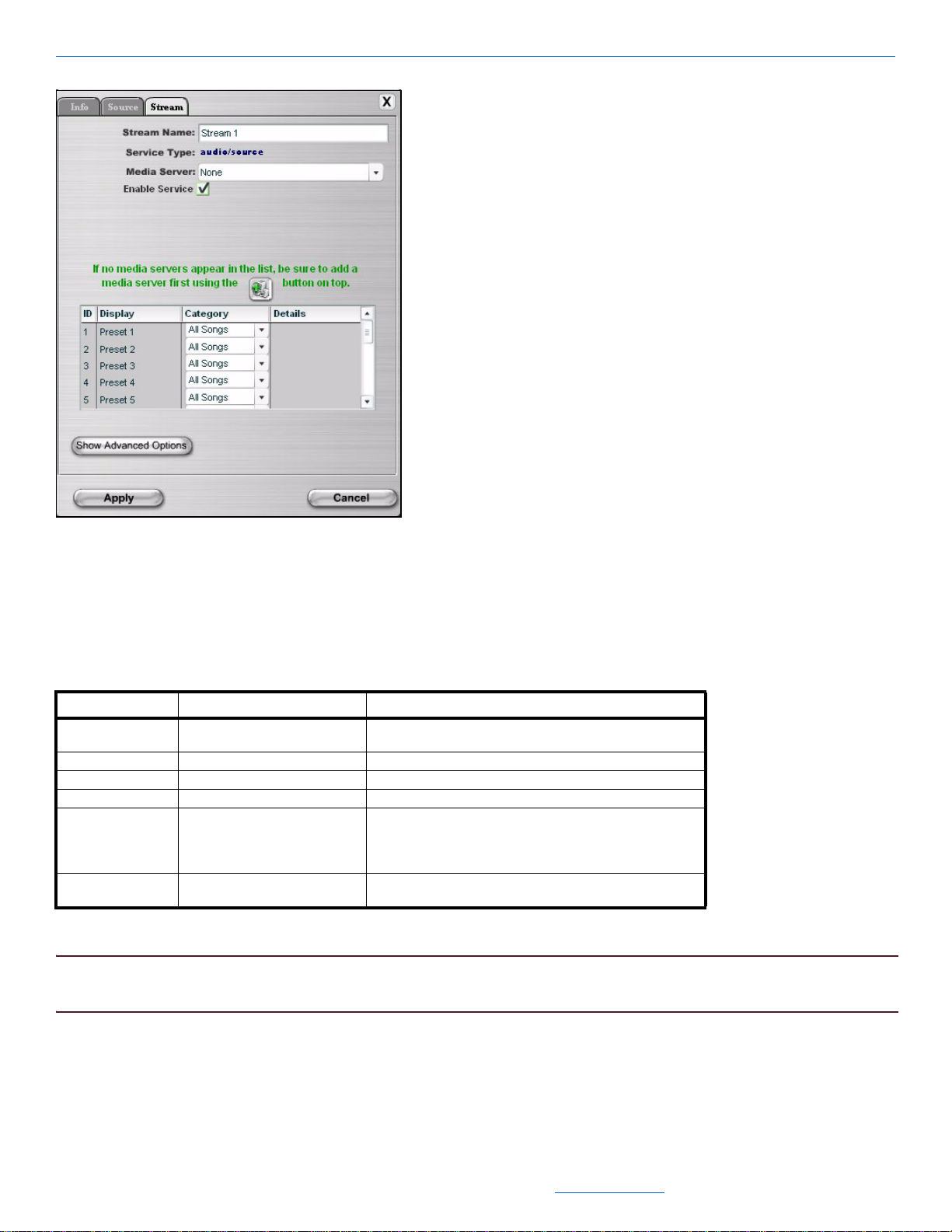
Editing Devices
Figure 5-20 MediaLinX MLA101 Stream tab
From this screen, you can select the media server and the stream the MediaLinX is hosting. You can also
disable the service.
Table 5-13 provides information on the fields available for editing the Stream tab.
Table 5-13
MediaLinX MLA101 Stream Tab
Tab Selection Description
Stream Service Name A display field used to identify the stream name. You can
click in this field to update the stream name.
Service Type A display field used to indicate the service type.
Media Server The brand of media server.
Enable Service Enables or disables functionality.
Presets Preset settings for that stream from a compatible media
Show Advanced Options Normally used for advanced configurations. Typically, the
server. Presets can be created for one-touch operation to
play back all songs by an artist, album, in a genre, or a
playlist.
installer will not use this screen.
6. After adjusting information on the Stream page, select Apply.
NOTE: At this point, you can Learn IR (see IR Tools in Chapter 7) to complete the MediaLinX configuration.
You can also complete the Wizard and Learn IR later prior to sending the configuration to the server.
Edits to the MediaLinX MLA101 are complete.
All specifications subject to change without notification. All rights reserved. Copyright © 2008 NetStreams
Main +1 512.977-9393 / fax +1 512.977.9398 / Toll Free Technical Support +1 866-353-3496
3600 W. Parmer Lane, Suite 100; Austin, TX 78727 / www.netstreams.com.
5-23
Page 94

DigiLinX Dealer Setup Version 2.35.00
MediaLinX MLA4000
This section describes the tabs for the MediaLinX Pro MLA4000, and tabs for a MediaLinX and ControLinX
contained in a MediaLinX Pro MLA4000.
This section describes the four tabs for the MediaLinX MLA4000:
Info
Slots
Input Sensors
Relays
MediaLinX MLA4000 Tabs
This section explains the tabs for the MediaLinX MLA4000.
MLA4000 Info Tab
1. Click the MediaLinX MLA4000 in your project list.
The Info tab for the MediaLinX MLA4000 displays in the right side of the window (see Figure 5-21).
Figure 5-21 MediaLinX MLA4000 Info tab
The Info tab contains all of the information about that particular MediaLinX. T able 5-14 provides information
on the fields on the Info tab.
5-24
All specifications subject to change without notification. All rights reserved. Copyright © 2008 NetStreams
Main +1 512.977-9393 / fax +1 512.977.9398 / Toll Free Technical Support +1 866-353-3496
3600 W. Parmer Lane, Suite 100; Austin, TX 78727 / www.netstreams.com.
Page 95

Table 5-14
MediaLinX MLA4000 Info Tab
Tab Selection Description
Info Current IP Address The current IP address of the MediaLinX.
Current Subnet Mask The current subnet mask of the MediaLinX.
Device Type The type of DigiLinX device that this is.
Model Number The NetStreams MediaLinX model number.
Firmware Version What firmware version is currently running on the MediaLinX.
Device Name Descriptive name the installer assigned to the device when
creating the project.
Override Changes the default device name. Keep unchecked in most
instances.
Serial Number Displays the MediaLinX serial number.
Device Comments Indicate where the device is installed so that if you need to
return to the installation for service or upgrading devices, you
can have access to this information in the project file.
Device Summary
Slots 1-5 Shows the five slot assignments for the ControLinX
MLA4000.
Show Advanced Options Normally used for advanced configurations. Typically, the
installer will not use this screen.
Editing Devices
2. After adjusting information on the Info page, select Apply.
MLA4000 Slots Tab
The MediaLinX MLA4000 is a highly configurable device. There are five hardware slots on the rear of the unit.
One of these slots (slot 5) is a ControLinX. The other slots (slots 1 through 4) can serve as either a MediaLinX or
a ControLinX. The installer can define how they want the slot to work on this screen.
1. Select the Slots tab.
The Slots tab information displays (see Figure 5-22).
All specifications subject to change without notification. All rights reserved. Copyright © 2008 NetStreams
Main +1 512.977-9393 / fax +1 512.977.9398 / Toll Free Technical Support +1 866-353-3496
3600 W. Parmer Lane, Suite 100; Austin, TX 78727 / www.netstreams.com.
5-25
Page 96

DigiLinX Dealer Setup Version 2.35.00
Figure 5-22 MediaLinX MLA4000 Source tab
The Slots tab displays each slot on the MLA4000 and shows the assigned device type. Slots 1-4 can be
assigned to function as a MediaLinX 101 or as a ControLinX. Slot 5 is a dedicated ControLinX.
2. You can change information on the Slots page. If you change any of the slot assignments, Dealer Setup will
ask for a service type such as a tuner for a MediaLinX or driver such as Lutron Radio RA for a ControLinX.
After adjusting information on the Slots page, select Apply.
MLA4000 Input Sensors Tab
You would use the Input Sensors tab if you are connecting the MediaLinX MLA4000 to a Doorbell/Telephone
Mute interface. The Input Sensor tab is used to configure how the input sensor is triggered and how it behaves.
1. Select the Input Sensors tab.The Input Sensor tab for the MediaLinX MLA4000 displays in the right side of
the window. Figure 5-23 shows the Input Sensors page.
5-26
All specifications subject to change without notification. All rights reserved. Copyright © 2008 NetStreams
Main +1 512.977-9393 / fax +1 512.977.9398 / Toll Free Technical Support +1 866-353-3496
3600 W. Parmer Lane, Suite 100; Austin, TX 78727 / www.netstreams.com.
Page 97

Editing Devices
Figure 5-23 MediaLinX MLA4000 Input Sensors tab
Connect an Elk Products Doorbell and Telephone Ring Detector (ELK-930),or similar device, to one of the
2.
modular plugs labeled Mute. You can have two detectors on an MLA4000.
Table 5-15 provides information on the fields available for editing the Input Sensor tab.
All specifications subject to change without notification. All rights reserved. Copyright © 2008 NetStreams
Main +1 512.977-9393 / fax +1 512.977.9398 / Toll Free Technical Support +1 866-353-3496
3600 W. Parmer Lane, Suite 100; Austin, TX 78727 / www.netstreams.com.
5-27
Page 98

DigiLinX Dealer Setup Version 2.35.00
Table 5-15
MLA4000 Input Sensor Tab
Tab Selection Description
Input Sensor Input 1 Sensor Trigger Level Provides the following sensor options:
High Signal
Low Signal
Signal Toggles
Input 1 Action Allows you to mute the signal by factors of 10, 15, or 30
seconds when the doorbell is pressed.
Sensor Adjustment Allows the installer to adjust the sensitivity of the sensor.
Input 2 Sensor Trigger Level Provides the following sensor options:
High Signal
Low Signal
Signal Toggles
Input 2 Action Allows you to mute the signal by factors of 10, 15, or 30
seconds when the doorbell is pressed.
Sensor Adjustment Allows the installer to adjust the sensitivity of the sensor.
NOTE: If using an ELK-930, set the Sensor Trigger Level to Signal Toggles, and set the Action to the desired
amount of time.
3. After adjusting information, select Apply.
1. Select the Relays tab.
The Relays tab information displays (see Figure 5-24).
Figure 5-24 MediaLinX 4000 Relays tab
5-28
All specifications subject to change without notification. All rights reserved. Copyright © 2008 NetStreams
Main +1 512.977-9393 / fax +1 512.977.9398 / Toll Free Technical Support +1 866-353-3496
3600 W. Parmer Lane, Suite 100; Austin, TX 78727 / www.netstreams.com.
Page 99

Editing Devices
2. The Relays tab displays settings for the four relays on the MLA4000. Relays can be set to Normally Open,
Normally Closed, or None.
3. After adjusting information on the Relays page, select Apply.
MediaLinX Contained in an MLA4000 - Source Tab
You can adjust the settings for each MediaLinX contained in a MLA4000.
1. Select the slot in the MLA4000 that you want to adjust settings for. The Source tab displays in the right side
of the window as shown in Figure 5-23.
Figure 5-25 Source tab for a MediaLinX in an MLA4000
The fields for the Source page are shown in Table 5-16.
Tab Selection Description
Source* Source Name This name appears as a selection on all user interfaces and
is used to identify the device.
Driver File The driver file for this particular audio source.
Source Type The type of source (tuner, CD player, etc.) connected to the
MediaLinX.
Input Select Allows you to select what kind of input the MediaLinX should
expect. Either Analog or S/PDIF.
All specifications subject to change without notification. All rights reserved. Copyright © 2008 NetStreams
Main +1 512.977-9393 / fax +1 512.977.9398 / Toll Free Technical Support +1 866-353-3496
3600 W. Parmer Lane, Suite 100; Austin, TX 78727 / www.netstreams.com.
5-29
Page 100

DigiLinX Dealer Setup Version 2.35.00
Tab Selection Description
Input Level Allows you to compensate for audio signal levels that are too
Power Sensor Power Sensing is the ability to tell whether a source
Enable Service Enables or disables functionality. If disabled, the MediaLinX
Presets Presets for the tuner.
Low Latency Tells the system to not buffer audio and video and use the
weak or strong. This ensures a consistent volume level
when switching sources.
component is powered on or off. The MediaLinX can use one
of three power sensing methods:
None - This method uses no power sensing.
Level. This method senses the source component’s
signal output level to determine if it is powered on or off.
LED. This method senses whether the LED on the source
component’s front panel is on or off to determine the
power state. An optional LED power sensor is sold
separately (NS-PS301LS).
Video Sync. This method senses video output from a
source component such as a DVD player, TV, or VCR.
will appear grayed out in Dealer Setup.
lowest latency.
NOTE: By default, this option is unchecked. NetStreams
uses a small amount of latency to account for
video processing delays at the display. Only use
the Low Latency setting in venues where a video
processing delay is not desired, such as live
performances.
Table 5-16 Source page
* Additional fields may display depending on the source selected.
NOTE: At this point, you can Learn IR (see IR Tools on page 7-1) to complete the MediaLinX configuration. You
can also complete the Wizard and Learn IR later prior to sending the configuration to the server.
ControLinX Contained in an MLA4000
There are four tabs for showing information on a ControLinX in an MLA4000:
IR/RS232 Settings
Labels
Menus
Input Sensor
These tabs are shown in Figure 5-26.
5-30
All specifications subject to change without notification. All rights reserved. Copyright © 2008 NetStreams
Main +1 512.977-9393 / fax +1 512.977.9398 / Toll Free Technical Support +1 866-353-3496
3600 W. Parmer Lane, Suite 100; Austin, TX 78727 / www.netstreams.com.
 Loading...