

Page 1

ClearCube Technology, Inc. 3700 W Parmer Lane Austin, TX 78727 (512) 652-3500 www.clearcube.com
Included in
container
The list below shows components included in a SmartVDI-110 container.
SmartVDI-110 Server
Chassis mounting rails and hardware
SATA DOM (for system startup)
Up to four storage drives (SSD, HDD, or both)
LSI SAS host bus adapter
NVIDIA GRID™ graphics card (optional, up to two)
Teradici® PCoIP® Offload card (optional)
Fiber NIC controller (optional)
Power cable(s)
This Quick Start Guide
Motherboard documentation
SAS host bus adapter documentation
If included in on server configuration, documentation for graphics card and PCoIP Offload card
Not included
The list below shows items not included with a SmartVDI-110 Server.
Monitors
Ethernet cables (copper)
Fiber optic cables
Keyboard and mouse
SmartVDI-110 Server Quick Start Guide
Container Contents
Page 1 of 10 P/N G0200181 Rev A, 1.0.12.14.2015
Page 2
ClearCube Technology, Inc. 3700 W Parmer Lane Austin, TX 78727 (512) 652-3500 www.clearcube.com
SmartVDI-110
overview
The SmartVDI-110 Server is a 1U, VDI-optimized, high-performance server based on the Intel® C612
chipset. The list below shows SmartVDI 110 features.
Intel Xeon® E5-2600 v3 series processor (up to 18 cores and 145 W)
16 × DIMM slots, 288-pin DDR4
Up to 512 GB DDR 4 ECC Registered Memory
16 or 32 GB RDIMM modules
4 × 2.5-inch SAS/SATA hot-swap drive bays
2 × 10GBASE-T (GbE) Ethernet LAN ports
1 × Ethernet dedicated IPMI port
Support for IPMI 2.0
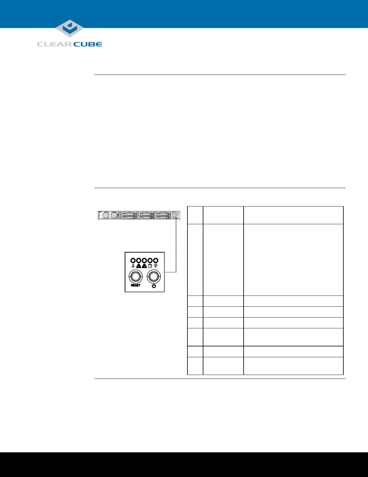
SmartVDI-110
front panel
The picture and table below show indicators and buttons on the front panel of a SmartVDI-110.
Indicator or
Button
Description
1
Overheat/
Fan Fail
Solid: overheat condition.
Flashing: fan failure.
To troubleshoot, ensure that cables do
not obstruct air flow, ambient room
temperature is appropriate, and all
fans are installed and operating. Also
ensure that the chassis cover, all
airflow shrouds, and all heat sinks are
installed properly.
2
NIC 2
Flashing: network activity.
3
NIC 1
Flashing: network activity.
4
HDD
Flashing: hard disk drive activity.
5
Power
(Indicator)
Solid: power is supplied to the server.
6
Reset
Press to restart the server.
7
Power
(Button)
Press to power on and power off
the server.
2
3 4 5
6
7
1
SmartVDI-110 Overview and Features
Page 2 of 10 P/N G0200181 Rev A, 1.0.12.14.2015
Continued on next page
Page 3
ClearCube Technology, Inc. 3700 W Parmer Lane Austin, TX 78727 (512) 652-3500 www.clearcube.com
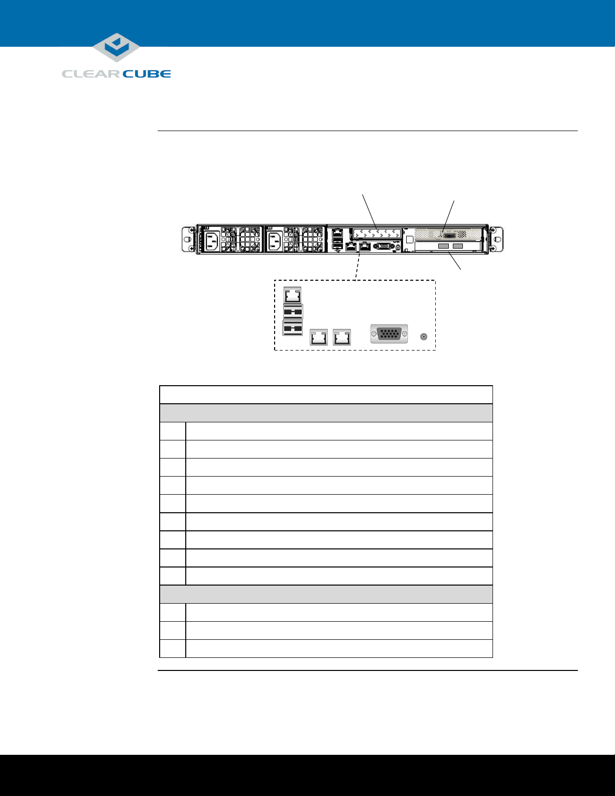
SmartVDI-110
rear ports and
connectors
The picture below shows ports, connectors, and buttons on the rear of a SmartVDI-110.
Description
Server I/0 Connectors
8
Power connector
9
Power connector
10
Dedicated IPMI LAN port
11
USB 1 port
12
USB 0 port
13
LAN 1 port
14
LAN 0 port
15
VGA port
16
Unit ID Button (press to illuminate LED for visual identification in rack)
I/O Cards
17
PCoIP offload card (optional)
18
LSI Host bus adapter
19
10GBASE-T (10 GbE) fiber NIC (optional)
8
9
10
11
12
13
14
15
16
17
18
19
PCoIP Offload Card
(Optional)
LSI Host Bust Adapter
Server I/O
10GBASE-T Fiber NIC
SmartVDI-110 Overview and Features, Continued
(Optional)
Page 3 of 10 P/N G0200181 Rev A, 1.0.12.14.2015
Page 4

ClearCube Technology, Inc. 3700 W Parmer Lane Austin, TX 78727 (512) 652-3500 www.clearcube.com
Rack rail
components
Two rack rail assemblies are included with a SmartVDI-110 Server. Each assembly has two sections:
Inner rails: attach to the workstation chassis (the inner rail is pre-attached), and
Outer rack rails: attach to rack
The picture below shows the inner chassis rails and the outer rack rails.
Inner Rail
Pre-Assembled
Attach to Chassis
Front and Rear Brackets to Rack
Front Bracket
Rear Bracket
Rack Rails and Mounting
Inner Rail Extension
Outer Rack Rails
Slide Front into Rear & Attach
Continued on next page
Page 4 of 10 P/N G0200181 Rev A, 1.0.12.14.2015
Page 5

ClearCube Technology, Inc. 3700 W Parmer Lane Austin, TX 78727 (512) 652-3500 www.clearcube.com
Install inner
rail extensions
The picture and table below show how to attach and secure the inner rail extensions.
Step
Action
1
Align the hooks on the side of the chassis with the slots on the inner rail extension.
2
Slide the extension rail toward the front of the chassis.
3
Secure the extension rail with the screws provided.
4
Repeat these steps to attach the other extension rail on the other side of the chassis.
Next step: assemble outer rack rails.
Assemble outer
rack rails
Outer rack rails consist of two sections: a longer front section and a shorter rear section. Slide these
together to assemble the rail.
Step
Action
1
Identify the left and right outer rack rails by examining the ends (brackets). These
brackets bend outward as shown in “Rack rail components.”
2
Slide the front section of the outer rack rail into the rear outer rack rail as shown in
“Rack rail components.”
3
Repeat these steps to assemble the other outer rack rail.
Next step: install outer rack rails in a rack.
Step 1
Step 2
Step 3
Step 3
Rack Rails and Mounting, Continued
Continued on next page
Page 5 of 10 P/N G0200181 Rev A, 1.0.12.14.2015
Page 6

ClearCube Technology, Inc. 3700 W Parmer Lane Austin, TX 78727 (512) 652-3500 www.clearcube.com
Install outer
rack rails
The picture and table below shows how to install the assembled outer rack rails in a rack.
Step
Action
1
Adjust the outer rack rails so that the outer
rails fit snugly in the rack.
2
Align the holes on the front of the outer rail
with the holes on the front of the rack and
secure with the screws provided (see A in
the adjacent picture).
3
Align the holes on the rear of the outer rack
rail with the holes on the rack and secure
with the screws provided (see B in the
adjacent picture).
4
Repeat these steps with the other outer rack
rail assembly.
Next step: Install the workstation in a rack.
Installing in
rack
To install a SmartVDI-110 Server in a rack:
1. While carefully lifting the workstation, slide the inner rail extensions into the front of the outer
rack rails.
2. Push the workstation into the rack until it clicks into the locked position.
Removing from
rack
This picture and table below show how to remove a SmartVDI-110 Server from a rack.
1. Press the outer rack rail latch to release the workstation
chassis (the latch is shown in the adjacent picture).
2. Carefully slide the chassis forward off of the outer rack
rails and out of the rack.
A
B
Rack Rails and Mounting, Continued
Page 6 of 10 P/N G0200181 Rev A, 1.0.12.14.2015
Page 7

ClearCube Technology, Inc. 3700 W Parmer Lane Austin, TX 78727 (512) 652-3500 www.clearcube.com
Cabling
This section shows how to connect cables. Numbers in parentheses correspond to labels shown in
“SmartVDI-110 front panel” and in “SmartVDI-110 rear ports and connectors” to ease identification.
Step
Action
1
Install the included mounting rails to the server chassis and then install the chassis
in a rack.
2
Connect one or more Ethernet cables to the LAN ports (13) and (14) on the rear of
the chassis and connect the other end of the cable(s) to a network router or switch.
3
Connect one or more Ethernet cables to the Dedicated IPMI port (10) on the rear
of the chassis and connect the other end of the cable to a network router or switch.
4
From the rear of the chassis, connect the included power cables to the power
connectors (8 and 9) on the rear of the server, and connect the power cable to a
power outlet.
5
From the front of the chassis, press the power button (7) to power on the server.
Power option
Press the power button (7) on the front of the chassis to power on and power off a workstation.
Standby power is present when a workstation is powered off.
Setting up a SmartVDI-110 Server
Page 7 of 10 P/N G0200181 Rev A, 1.0.12.14.2015
Page 8

ClearCube Technology, Inc. 3700 W Parmer Lane Austin, TX 78727 (512) 652-3500 www.clearcube.com
About BIOS
settings
Some SmartVDI-110 Server hardware configurations require specific BIOS settings. The sections
below show how to access the BIOS, how to configure the BIOS for an IPMI controller, and how to
configure the BIOS for NVIDIA® GRID graphics cards.
Accessing the
BIOS
The table below shows how to access the SmartVDI-110 Server BIOS.
Step
Action
1
Connect a keyboard and VGA monitor to the server.
2
Power on the server or reset server power.
3
Watch the server splash screen for prompts. When prompted, press the DELETE
key to enter the BIOS setup utility.
You can now use the arrow keys on the keyboard to navigate the BIOS menus.
IPMI
configuration
SmartVDI-110 Servers include an IPMI 2.0 + KVM (keyboard, video and mouse) management
controller. This IPMI controller uses a dedicated IP address, and the default setting is for a DHCPassigned network address. ClearCube recommends giving the controller a static IP address. You can
easily change this setting from the BIOS.
Step
Action
1
Access the BIOS as shown above in “Accessing the BIOS.”
2
Use the keyboard arrow keys to select the IPMI menu.
3
Select BMC Network Configuration. Press ENTER.
4
Select Update IPMI LAN Configuration, and press ENTER. Select Yes, and then
press ENTER.
5
Select Configuration Source and press ENTER.
6
Select Static and press ENTER.
7
Use the keyboard to configure the Station IP Address, Subnet Mask, and Gateway IP
addresses as appropriate for your environment. Select each item and press ENTER
to activate the text entry field. Enter an IP address for each item and press ENTER
to set the address.
8
If your server configuration includes one or more NVIDIA GRID graphics cards,
continue to the next section. Otherwise, press the F4 key to save your changes and
exit the BIOS. See the note below about accessing IPMI utilities.
Next steps: After saving your changes you can use a Java®-enabled browser or the Supermicro® IPMI
tool to access the server’s IPMI utilities. The default user name is ADMIN and the default password
is ADMIN (both values are case-sensitive.)
Important BIOS Settings
Continued on next page
Page 8 of 10 P/N G0200181 Rev A, 1.0.12.14.2015
Page 9

ClearCube Technology, Inc. 3700 W Parmer Lane Austin, TX 78727 (512) 652-3500 www.clearcube.com
NVIDIA GPU
configuration
If your server includes one or more optional NVIDIA GRID graphics cards, set the graphics card
memory access point below the system’s first 4 GB of physical memory. Specify this setting in the
BIOS to guarantee the memory configuration. The steps below show how to change the BIOS setting.
Step
Action
1
Access the BIOS as shown above in “Accessing the BIOS.”
2
Use the keyboard arrow keys to select the Advanced menu.
3
Select the Above 4G Decoding option. Press ENTER.
4
Select Disable and press ENTER.
5
Press the F4 key to save your changes and exit the BIOS.
Important BIOS Settings, Continued
Page 9 of 10 P/N G0200181 Rev A, 1.0.12.14.2015
Page 10

ClearCube Technology, Inc. 3700 W Parmer Lane Austin, TX 78727 (512) 652-3500 www.clearcube.com
WEEE Disposal Guidelines
In the European Union, this electronic product falls under the European Directive (2002/96/EC) WEEE. When it reaches
the end of its useful life or is no longer wanted, it should not be discarded with conventional waste, but disposed of at
an approved designated recycling and/or treatment facility. Laws are different in each country, so please check with
your local authorities for proper disposal instructions. For assistance, contact ClearCube at
Related
information
The table below shows additional documents about server configuration, operation, and maintenance.
For information about …
See …
Deployment guidelines for SmartVDI servers
SmartVDI Converged Infrastructure Platform
Deployment Guide
NVIDIA GRID graphics card configuration
GPU Quick Install Guide included with the
SmartVDI server
Installation services
Contact ClearCube or your Authorized
ClearCube Reseller.
ClearCube documentation is located at http://www.clearcube.com/support/.
Contacting
Support
Web
UUUwww.clearcube.com/support/
Email
UUUsupport@clearcube.com
Toll-free
(866) 652-3400
Direct
(512) 652-3400
Related Information and Support
recycle@clearcube.com.
Page 10 of 10 P/N G0200181 Rev A, 1.0.12.14.2015
 Loading...