

Page 1
R1350 PC Blade
Quick Start Guide
ClearCube® R1350 PC blades deliver a high-density, high-performance computing
solution with the following features:
• Up to Core® 2 Duo processor, 1066 MHz FSB
• Up to 4 GB RAM
• One 3 Gbps SATA II hard disk drive
• Two Ethernet controllers: one gigabit controller and, depending on blade
configuration, one 10/100 megabit controller or one Teradici® PC–over–IP®
controller
• Quad, dual, or single monitor support, depending on configuration
Installation
The interposer on the rear of the R1350 blade determines the chassis in which you can
install the blade.
• 44–pin interposer—This default configuration enables you to install the R1350
blade in the R4300 chassis
•
30–pin interpose
install the R1350 blade in an R4200 or in an R4300 chassis. If you use a 30–pin
interposer with the R4300 chassis, you cannot use the USB port on the rear apron
of the chassis.
r—Available as a downgrade kit, this interposer enables you to
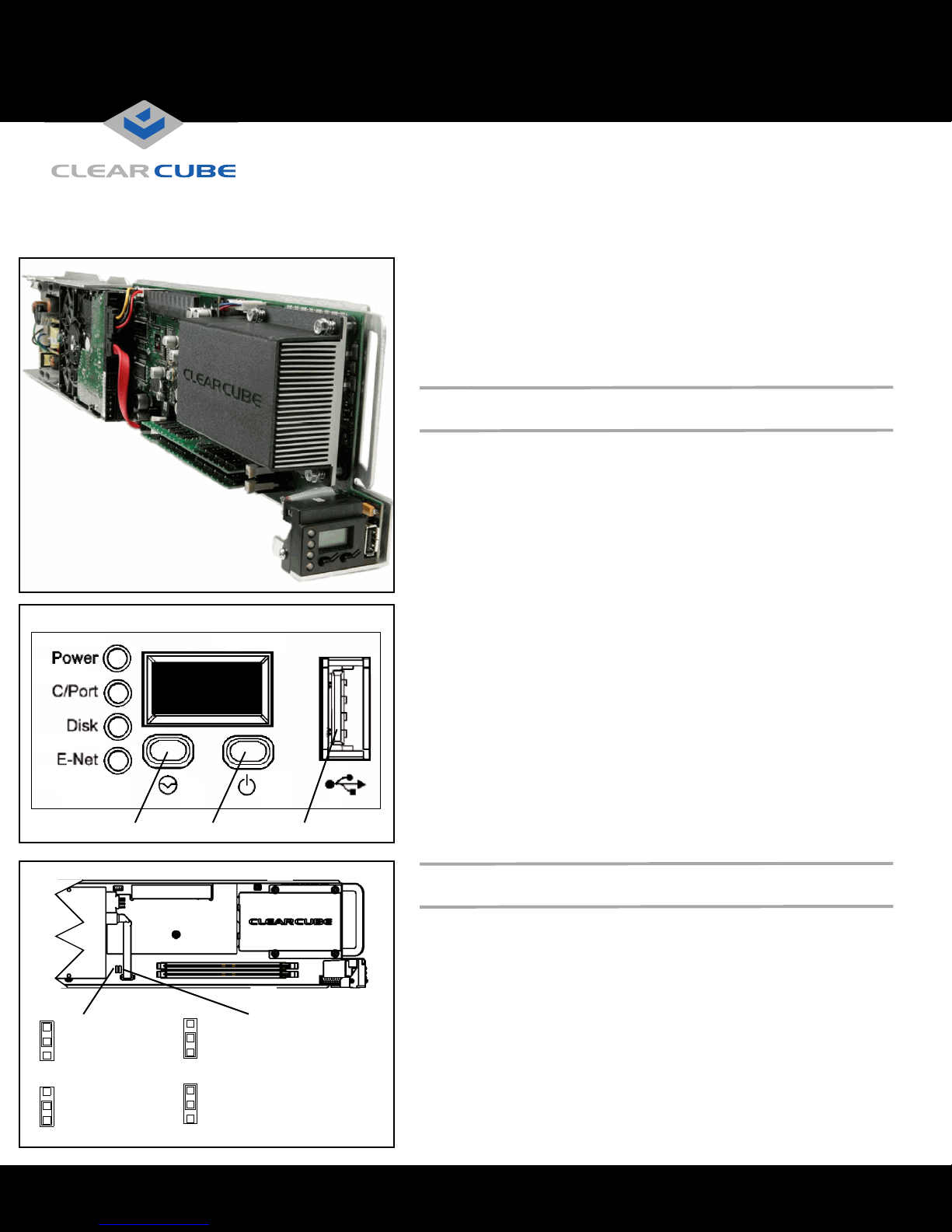
Reset Power USB Port
MSL Jumper JP6
3
USB Mass Storage
devices function
1
normally (default)
LCD Panel
245
3
CMOS Jumper JP1
Normal operation
(default)
1
To install an R1350 blade, perform the following steps:
1. Open the front bezel on the chassis by depressing the latches on each side. Pull the
bezel toward you.
2. Hold the blade so the LCD panel is facing you and on the bottom. Align the blade
edges with the top and bottom guides in the chassis and slowly insert the blade into
the chassis. There is a slight resistance when you insert the back connector
(interposer) into the backplane socket.
3. After inserting all blades, raise the front bezel and snap it into place.
4. Depress the power button on the front of the blade to start it.
Note: The first time you insert the R1350 blade, the power does not start automatically.
You must press the power button on the front of the blade to start it. After the first
time you start the blade, the blade uses its stored power setting to determine its
unattended power-on behavior.
When you insert a blade into a chassis and start it, it takes approximately 30 seconds
for the chassis and its Remote Management Module (RMM) to detect the blade and
relay its information to Sentral.
Setting CMOS Password and Mass Storage Lockout
The R1350 provides jumpers that control CMOS password clearing and Mass
Storage Lockout (MSL). The default jumper settings are:
• JP1—Pins 1 and 2 are jumpered; CMOS password is retained on restart.
• JP6—Pins 2 and 3 are jumpered; MSL control is enabled in software.
MSL Jumper
3
USB Mass Storage
devices do not
1
function
ClearCube Technology 8834 Capital of Texas Hwy N Austin, Texas 78759 voice 512 652 3500 www.clearcube.com
CMOS Jumper
3
Clears CMOS
password on
1
restart
Page 2
Monitor Support
Upgrading R1350 Memory
The following table lists each R1350 video option and the number of
supported monitors for each option.
Graphics Option
Intel® GMA 950 integrated graphics engine X
NVIDIA® Quadro®4 PCI-Express® card X X X
V5120 Dual Host card X X
Single
Monitor
Dual
Monitor
Quad
Monitor
Video Options and Ethernet Port Behavior
The R1350 provides two Ethernet ports that correspond to the primary and
secondary Ethernet jacks on a chassis. Your graphics card configuration
determines the behavior of the R1350 Ethernet ports.
• V5120 Dual Host card—R1350 blades with V5120 graphics cards
enable you to connect to I9420 I/Ports or C7420 C/Ports through the
secondary Ethernet port. The primary port provides gigabit Ethernet.
• Quadro4 PCI-Express card and GMA 950 integrated graphics—
R1350 blades using either of these graphics options provide two
independent network connections. The primary Ethernet controller
provides gigabit Ethernet. The secondary Ethernet provides 10/100
Ethernet. The dual Ethernet ports on the R1350 are accessible as
follows:
– 16-port EP6 module in R4300 chassis—All ports are available.
The primary ports on the blade are connected to the
corresponding primary ports on the EP6, and the secondary ports
on the blade are connected to the corresponding secondary ports
on the EP6. If Ethernet port availability in the data center is an
issue, connect to the primary Ethernet ports on the EP6 first.
– R1350 installed in an R4200 chassis—Only the primary port on
the R1350 is connected.
WEEE Disposal Guidelines
In the European Union, this electronic
product falls under the European Directive
(2002/96/EC) WEEE. When it reaches the
end of its useful life or is no longer wanted,
it should not be discarded with conventional
waste, but disposed of at an approved
designated recycling and/or treatment
facility.
Laws are different in each country, so
please check with your local authorities for
proper disposal instructions.
For assistance, contact ClearCube at
recycle@clearcube.com
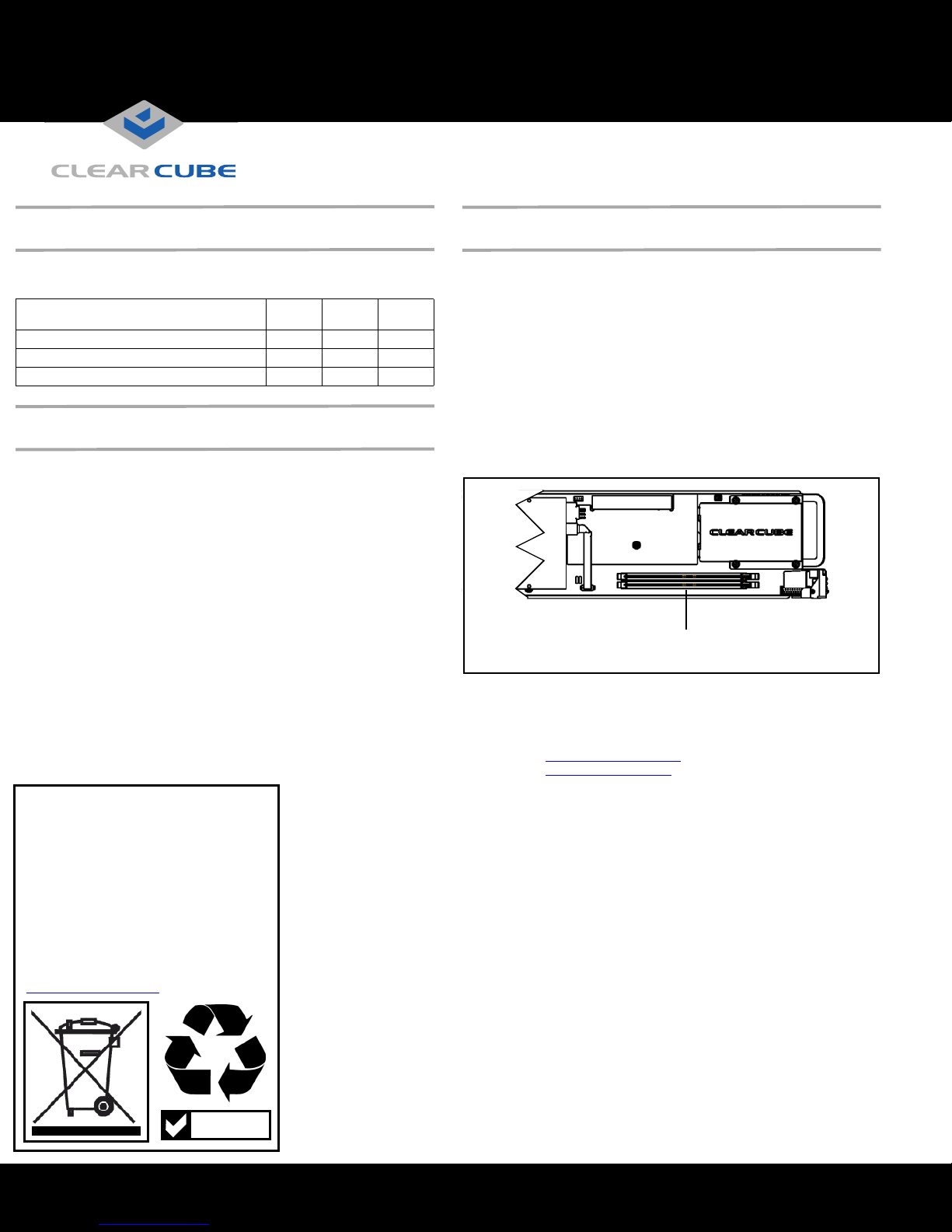
Only use memory that ClearCube supplies. R1350 blades support
a single
DIMM and two DIMMs of different sizes and speeds. When you install
DIMMs of equal size, the
R1350
memory controller uses interleaved
memory mode for better performance.
To replace or upgrade memory, perform the following steps:
1.
Pull the tabs on either side of the memory socket apart to remove the
memory module.
2. Carefully insert the new memory module into the socket, making sure
that the tabs snap inward to secure the module. Always populate slot U5
(closest to the bottom of the blade) first.
Note: If DIMMs are equal in size but mismatched in speed or timing, the
blade runs at the slower of the two speeds. With mismatched DIMM
sizes, the system always runs in non-interleaved mode at the slower
speed or timing of the two DIMMs.
DIMM Slots
Populate Bottom Slot First
The R-Series Data Center Products Reference Guide contains more
information about the R1350 blade.
For more information, please contact ClearCube Technical Support.
Email:
support@clearcube.com
Web site: support.clearcube.com
Toll-free: (866) 652-3400
Phone: (512) 652-3400
RoHS
ClearCube Technology 8834 Capital of Texas Hwy N Austin, Texas 78759 voice 512 652 3500 www.clearcube.com
G0200101 Rev A
 Loading...