

Page 1
R3040S Server Blade Quick Start Guide
138
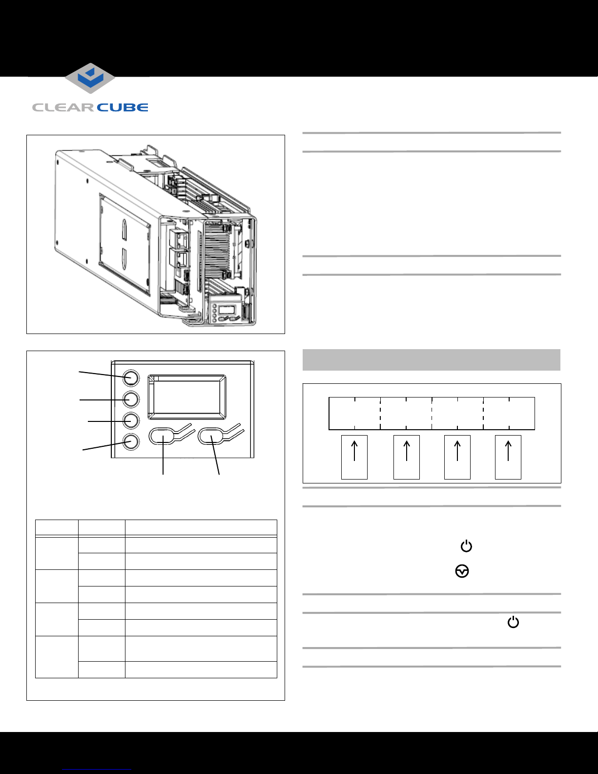
Power
Disk Activity
Reset Button Power Button
Ethernet
Connection
C/Port
Link
138
The following table details the front panel indicators shown above.
LED State Description
Power
Green Blade is powered on.
Off Blade is powered off.
C/Port
Green C/Port is connected and link is good.
Red C/Port is not connected or link is bad.
Disk
Green Flashing indicates hard drive activity.
Off No hard disk activity.
E-Net
Green 10/100/1000 Mbps link. Flashing
indicates activity.
Off No link.
Blade
Slots 1 & 2 Slots 3 & 4 Slots 5 & 6 Slots 7 & 8
Chassis
BladeBladeBlade
R3040S Overview
Your ClearCube® R3040S Server blade is preconfigured with the
components and software you ordered (consult your shipping invoice
or sales representative for details). If you purchased Windows
Server 2008, your shipment contains DVDs containing the OS.
In typical ClearCube environments, R3040S blades are centrallylocated in data centers. Each blade user has a user port (such as a
ClearCube I94x0 client, ClearCube C/Port, or thin client) on their
desk connected over a network to an R3040S blade. User ports
provide the interface to the blade.
Only Insert Blades in Specific Chassis Slots
Install R3040S in a ClearCube R4300-series chassis to provide
power, network connections, and more. (If you have an R4200series chassis, contact your ClearCube Sales Representative to
determine which R3040S features your chassis supports).
The R3040S blade use two chassis slots. Each blade must be
inserted in a chassis slot pair that begins with an odd number.
®
ClearCube Technology 8834 Capital of Texas Hwy N Austin, Texas 78759 voice 512 652 3500 www.clearcube.com
NOTE:
You must insert the R3040S in one of the following
chassis slot pairs: 1 & 2 / 3 & 4 / 5 & 6 or 7 & 8.
Powering on and Restarting the R3040S
When you insert an R3040S in a chassis, the blue LCD and green
power indicator are illuminated, indicating that the blade power is
in a standby state.
To power on the blade, press the Power ( ) button located on the
right-hand side of the LCD panel, as shown in the adjacent figure.
To restart the blade, press the Restart ( ) button, located on the
left-hand side of the LCD panel.
Powering Down the R3040S
To power down the R3040S, gently press the power ( ) button.
You can then remove the blade from the chassis as described below.
Removing R3040S from a Chassis
To remove an R3040S from a chassis, open the chassis door and press
the power switch, located on the right-hand side of the LCD panel.
Wait for the green power light to turn off. Hold the blade by the
handle and pull back to remove the blade. Ensure that you support the
—Continued—
Page 2
rear of the blade as you remove it from the chassis.
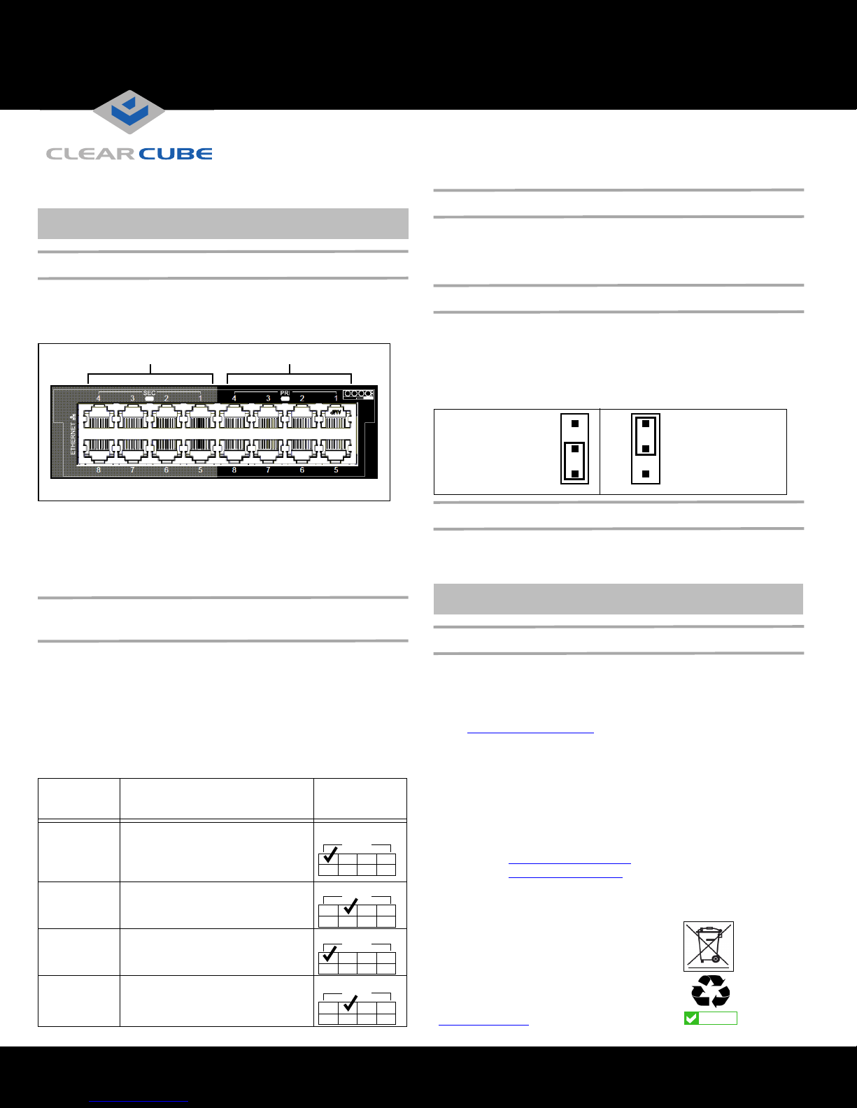
Secondary Ports Primary Ports
R4300 Chassis Network Module
2
3
1
2
3
1
MSL Disabled
Access to USB
Device Is
Permitted
(Default Setting)
MSL Enabled
Access to USB
Device Is Prohibited
In the European Union, this electronic product falls under
the European Directive (2002/96/EC) WEEE. When it
reaches the end of its useful life or is no longer wanted,
do not discard it with convention al waste; dispose of it at
an approved designated recycling and/or treatment
facility.
Laws are different in each country, so please check with
your local authorities for proper disposal instructions.
For assistance, contact ClearCube at
recycle@clearcube.com
RoHS
WEEE Disposal Guidelines
CAUTION:
Use care when handling R3040S blades; some
surface might be hot.
Network Cabling
Because R3040S blades use two slots in a chassis, the rear of a
ClearCube chassis (shown below) provides up to 4 Gigabit
Ethernet ports (2 primary ports and 2 secondary ports) for each
blade, depending on video card configuration.
C/Port Cabling
When connecting a C/Port to an R3040S, only use C/Port
connectors 2, 4, 6, or 8 on the Connect Bay Module (located on
the far left side of the chassis). For example, if an R3040S is in
chassis slots 3 and 4, connect your C/Port to connector 4.
Mass Storage Lockout
The R3040S motherboard provides a jumper for mass storage
lockout (MSL). MSL is disabled by default. When enabled, this
feature prevents users from connecting mass storage devices (USB
drives, flash drives, thumb drives) to user ports connected to the
blade. The MSL jumper is JP6, located in front of the memory
module slots on the top of blade.
Traditional video card: 4 Gigabit Ethernet NICs. Primary &
secondary ports of both slots the blade occupies are Gigabit Ethernet.
V52x0 card: 3 Gigabit Ethernet NICs. The odd-numbered secondary
port is for PCoIP communication. The three other ports
corresponding to the slots the blade occupies are Gigabit Ethernet.
How OS Network Connections Are Mapped to
NICs on Chassis Backpack
After you insert a blade in a chassis, your Windows operating
system shows 4 network connections in the Network Connections
window (click Start > Control Panel and then double-click
Network Connections to display all connections). The following
table shows how each Ethernet port on the Chassis Network
Module (on the rear of the chassis and shown above) is mapped to
each network connection that your OS displays (the following
examples assume that the blade is inserted in chassis slots 3 and 4).
LAN
Connection
Name
Local Area
Connection
Local Area
Connection 2
Ethernet Port Mapping on
Chassis Backpack
Mapped to the 2nd (higher number)
port in the pair of Primary ports
Mapped to the 1st (lower number) port
in the pair of Primary ports
Port Location (If
Blade Is in Slots
3 & 4)
4321
PRI
4321
PRI
Memory Modules
The R3040S contains 6 slots for DDR3-1333 memory modules. A
minimum of one memory module is required for each processor on the
blade (maximum of 2 processors per blade).
NOTE:
Most 32-bit operating systems support a maximum of 4
GB of RAM.
PCoIP Video Configuration and More
If your blade contains a PCoIP host card, see PCoIP User’s Guide
for information about configuring video with a ClearCube PCoIP
zero client. See R-Series User’s Guide for more information about
using and configuring the R3040S.
From support.clearcube.com
1.
Under the
product support
– For PCoIP, select PCoIP under Software.
– For R3040S, select R3040S under PC Blades.
2. Click the Manuals link under the product description.
3. To display the manual, click the document title link. Ensure that
you select the latest revision.
Email: support@clearcube.com
Web site: support.clearcube.com
Toll-free: (866) 652-3400
Phone: (512) 652-3400
:
area, click a drop-down box:
Local Area
Connection 3
Local Area
Connection 4
Mapped to the 2nd (higher number)
port in the pair of Secondary ports
Mapped to the 1st (lower number) port
in the pair of Secondary ports
ClearCube Technology 8834 Capital of Texas Hwy N Austin, Texas 78759 voice 512 652 3500 www.clearcube.com
4321
SEC
4321
SEC
G0200116 Rev C
 Loading...