

Page 1

PC-over-IP
) System User’s Guide
Revision C 1.2.03.03.2013
®
(PCoIP
®
Page 2

Technical Support
See the support Web site for technical updates, additional warranty information and documentation, and software
revisions:
Web http://www.clearcube.com/support
Email: support@clearcube.com
Phone: (512) 652-3400 or call toll free
(866) 652-3400 (United States)
ClearCube Technology, Inc. Corporate Headquarters
ClearCube
3700 W Parmer Ln
Austin, Texas 78727
E-mail info@clearcube.com
Main Phone: (512) 652-3500 or call toll free (866) 652-3500 (United States)
Main Fax: (512) 652-3501
Or contact your local ClearCube Reseller or Authorized Service Provider
Copyrights
© 2014 by ClearCube Technology, Inc. All rights reserved. Under copyright laws, this publication may not be
reproduced or transmitted in any form, electronic or mechanical, including photocopying, recording, storing in an
information retrieval system, or translating, in whole or in part, without the prior written consent of
ClearCube Technology, Inc.
This information is subject to change without notice and ClearCube shall not be liable for any direct, indirect, special,
incidental or consequential damages in connection with the use of this material.
Trademarks
ClearCube™, Sentral™, Blade Switching BackPack™, PC Blade™, C/Port™, and I/Port™ are trademarks of
ClearCube Technology Inc. Teradici, PC-over-IP, and PCoIP are registered trademarks of Teradici Corporation in the
United States and/or other countries. Windows and Windows Vista are registered trademarks of Microsoft Corporation
in the United States and/or other countries. All other trademarks are the property of their respective owners.
Patents
The ClearCube Architecture and its components described in this user manual are protected by numerous granted and
pending U.S. and international patents. Granted patents include: US05926172, US05966056, US05994952,
US06012101, US06020839, US06037884, US06038616, US06119146, US06148182, US06167241, US06385666,
US06421393, US06426970, US06633934, US06708247, US06735658, and US06886055.
Patents pending include: US S/N 09/755378, US S/N 10/279475, US S/N 10/198719, US S/N 10/198650, US S/N
10/409219, US S/N 09/728667, US S/N 09/728669, US S/N 10/411804, US S/N 10/411908, US S/N 10/458853, US S/N
10/364584, US S/N 10/301536, US S/N 60/411066, US S/N 10/662933, US S/N 10/662889, US S/N 10/662932, US S/N
10/662968, US S/N 10/301563, US S/N 10/662936, US S/N 10/301518, US S/N 10/662955 and US S/N 10/662954.
Inquiries regarding patented technology should be directed to ClearCube Corporate Headquarters
Page 3

Contents
Chapter 1. Introduction ................................................................................... 1
1.1 What is PC-over-IP? ....................................................................................................... 1
1.2 Component and Interface Overview ................................................................................ 3
1.2.1 Zero Client ........................................................................................................... 3
1.2.2 Host Card ............................................................................................................. 5
1.3 TERA2 and TERA1 Processors ...................................................................................... 5
1.4 Device Interfaces ............................................................................................................ 6
1.4.1 Web Interface ....................................................................................................... 6
1.4.2 On-Screen Display (OSD) .................................................................................... 8
1.5 Terminology Used in This Guide .................................................................................... 8
Chapter 2. Connection Modes and Network Topology ............................... 12
2.1 Device Management and Peer Assignment Options ....................................................... 12
2.2 Peer Assignment ................................................................ ........................................... 13
2.2.1 Static Assignment (Direct Connection) ............................................................... 13
2.2.2 SLP Discovery ................................................................................................... 14
2.3 IP Address Assignment ................................................................................................. 15
2.3.1 DHCP ................................................................................................................ 15
2.3.2 Reserved IP Addresses Using DHCP .................................................................. 16
2.3.3 Static IP ............................................................................................................. 18
2.4 Network Topology ........................................................................................................ 18
Chapter 3. Network Considerations ............................................................. 20
3.1 Important Device Configuration Steps .......................................................................... 20
iii
Page 4

3.2 Overview and Terms..................................................................................................... 20
3.3 User Experience ........................................................................................................... 22
3.4 Bandwidth Effects on Usability................................ ..................................................... 23
3.5 Typical Bandwidth Usage ............................................................................................. 24
3.5.1 User Types and Bandwidth Consumption ........................................................... 24
3.5.2 Limiting Screen Saver Bandwidth Consumption ................................................. 25
3.6 Bandwidth Limiting ...................................................................................................... 25
3.6.1 Device Bandwidth Limit .................................................................................... 26
3.6.2 Device Bandwidth Target ................................................................................... 27
3.6.3 Device Bandwidth Floor ..................................................................................... 27
3.6.4 Image Quality .................................................................................................... 28
3.7 Network Separation ...................................................................................................... 30
3.8 Port and Protocol Requirements .................................................................................... 31
Chapter 4. Initial Setup .................................................................................. 33
4.1 Caution Statements ....................................................................................................... 33
4.2 Mandatory Mounting, Cooling, and Airflow Provisions ................................................ 34
4.2.1 Ensuring Adequate Clearance around Zero Clients ............................................. 34
4.2.2 Ensuring Proper Client Mounting ....................................................................... 34
4.2.2.1 Desktop Mounting .......................................................................................... 35
4.2.2.2 Horizontal Mounting: Open Vents Must Face Up ........................................... 36
4.3 Cabling ......................................................................................................................... 36
4.3.1 Chassis Cabling Overview .................................................................................. 36
4.3.2 A-Series Chassis Ports........................................................................................ 37
4.3.3 R-Series Chassis Ports (Network Module) .......................................................... 38
4.4 Mandatory Network-Related Settings............................................................................ 39
4.4.1 Copper-Based Devices ....................................................................................... 40
4.4.2 Fiber-Based Devices .......................................................................................... 40
4.4.3 Drivers and Requirements .................................................................................. 41
4.5 Image Creation Requirements ....................................................................................... 42
4.6 Viewing Pre-OS Video (BIOS Configuration) and USB Input ....................................... 44
4.6.1 A-Series Blades .................................................................................................. 44
iv PCoIP System User’s Guide
Page 5

4.6.2 R-Series Blades .................................................................................................. 46
4.6.2.1 Using a Zero Client ........................................................................................ 46
4.6.2.2 Using a ClearCube C/Port (Analog) ................................................................ 49
Chapter 5. Zero Client Controls and Supported Power States .................. 51
5.1 Buttons and Indicators .................................................................................................. 51
5.2 Power Operations ......................................................................................................... 53
5.2.1 Soft Power Off (S5)............................................................................................ 53
5.2.2 Hard Power Off (S5) .......................................................................................... 53
5.2.3 Hibernate (S4) ................................................................ .................................... 53
5.2.4 Restart................................................................................................................ 53
5.2.5 Standby (S3) ...................................................................................................... 54
5.2.6 Sleep (S1 and S2) ............................................................................................... 54
Chapter 6. Configuring Devices, Setting Peers, and Connecting .............. 55
6.1 Finding a Device’s IP Address and MAC Address ........................................................ 56
6.1.1 External IP Address Is Not the PCoIP Processor IP Address ............................... 57
6.1.2 Finding an IP Address or MAC Address Using ClearCube Sentral ...................... 57
6.1.3 Finding Zero Client IP or MAC Address Using OSD .......................................... 60
6.1.4 Finding a Device’s IP Address Using a TCP/IP Port Sweep ................................ 60
6.1.5 Using Default Device Fallback IP Addresses ...................................................... 61
6.1.6 More about Device IP and MAC Addresses ........................................................ 62
6.2 Configuring Zero Clients and Host Cards ...................................................................... 62
6.3 Using the Web Interface ............................................................................................... 63
6.3.1 Web Interface Details ......................................................................................... 65
6.3.2 Using the On-Screen Display (OSD) .................................................................. 65
6.4 Configuring Blades ....................................................................................................... 67
6.4.1 Blade Video Settings .......................................................................................... 67
6.4.2 Enabling Audio on a 64-bit OS ........................................................................... 67
6.5 Specifying a Device’s Peer ........................................................................................... 68
6.6 Connecting to a Device ................................................................ ................................. 71
6.6.1 Unmanaged Static IPs with a Static Assignment ................................................. 71
6.6.2 Unmanaged Direct Connection with SLP Discovery ........................................... 75
ClearCube Technology, Inc. v
Page 6

6.6.3 Unmanaged Static IPs with Direct Connection .................................................... 78
6.6.3.1 Direct Connection Best Practices .................................................................... 81
6.6.3.2 Configuring Devices in Direct Connection ...................................................... 81
6.6.4 Unmanaged DHCP with SLP Discovery ............................................................. 82
6.6.5 Managed Environments Using ClearCube Sentral ............................................... 85
6.7 Configuring Video Settings........................................................................................... 85
6.7.1 Enabling and Disabling Displays Using the GPU Driver ..................................... 86
6.7.2 Additional Video Configuration Steps ................................................................ 86
6.8 Managing Sessions (Connections) and Device Behavior ............................................... 88
6.8.1 Session Control and Peer Information ................................................................. 88
6.8.2 Setting Devices to Automatically Reconnect....................................................... 90
6.8.3 PCoIP Sessions When Sentral Users Log off Operating System .......................... 91
Chapter 7. Changing Device Peers ............................................................... 93
Chapter 8. Mass Storage Lockout (MSL) ..................................................... 95
8.1 MSL Recommendations and Best Practices ................................................................... 95
8.2 Setting MSL on R-Series Blades ................................................................................... 96
8.3 Setting MSL on A-Series Blades ................................................................................... 98
8.3.1 MSL on A6106D and Higher .............................................................................. 99
8.3.2 MSL on A6105D and Lower .............................................................................. 99
8.4 Setting MSL from a Zero Client or Host Card Web Interface ...................................... 100
Chapter 9. Updating Device Firmware ....................................................... 104
9.1 Update Prerequisites ................................................................................................... 105
9.2 Identify Firmware on Device You Are Updating ......................................................... 105
9.3 Upload Firmware to Device ........................................................................................ 106
9.4 Resetting Devices after Firmware Installation ............................................................. 106
9.4.1 Zero Client ....................................................................................................... 106
9.4.2 Host Card ......................................................................................................... 107
9.5 Troubleshooting Firmware Updates ............................................................................ 107
Appendix A: Best Practices ............................................................................ 108
vi PCoIP System User’s Guide
Page 7

Appendix B: Troubleshooting ........................................................................ 111
Can’t set or change peer for a device .................................................................................. 111
“No route to host” message................................................................................................. 112
PCoIP does not support all power states .............................................................................. 113
Host cards do not respond to ARP requests ......................................................................... 113
Connected to 100-Mbit, full-duplex switch: poor performance, not full-duplex ................... 114
Zero client does not connect to blade (DHCP disabled or IP address changed) .................... 114
USB device connected to zero client, gray dialog box displayed ......................................... 115
Zero client video degrades or displays do not work ............................................................... 115
Poor or no audio on a host running a 64-bit OS ................................................................... 116
Appendix C: PCoIP Management and ClearCube Sentral ............................ 117
Appendix D: Zero Client and Host Card Web Interfaces .............................. 118
ClearCube Technology, Inc. vii
Page 8

Chapter 1. Introduction
This document:
Provides a brief overview of PC-over-IP® (PCoIP®) technology (see 1.1 “What is PC-over-
IP?” below)
Describes ClearCube zero clients and host cards that use PCoIP technology (see 0“
Component and Interface Overview” on page 3)
Describes methodologies IT administrators can use to deploy ClearCube zero clients and host
cards in their environment (see Chapter 2 “Connection Modes” on page 12)
Provides step-by-step instructions explaining how to deploy and connect devices (see Chapter
6 “Configuring Devices, Setting Peers, and Connecting” on page 55)
Identifies best practices for deploying and using ClearCube zero clients and host cards (see
Appendix A: “Best Practices” on page 108)
Provides troubleshooting tips (see Appendix B: “Troubleshooting” on page 111)
Explains the zero client and the host card Web interface (see 6.3 “Using the Web Interface”
on page 63 and Appendix D: “Zero Client and Host Card Web Interfaces” on page 118)
1.1 What is PC-over-IP?
PC-over-IP® (PCoIP®) technology is a display compression technology that enables organizations
to consolidate and manage any enterprise computer—including VMs and desktops for power
users—in a secure data center. PCoIP technology compresses, encrypts and encodes the entire
1
Page 9
Chapter 1. Introduction
computing experience in the data center and transmits it across a standard IP network to a zero
client—a stateless desktop device—for an exceptional user experience.
Devices using PCoIP technology contain PCoIP processors that process display images at the
pixel level, eliminating any dependence on the blade CPU or GPU. External display processing
provides complete independence from the host PC or workstation operating system and
applications. This architecture enables unlimited desktop performance scalability, including
application in high-end imaging and visualization. Devices using PCoIP technology provide users
with high-resolution, full-frame-rate 3D graphics; HD media; and full USB peripheral
interoperability locally over a LAN or remotely over a high-latency WAN.
Consolidating IT resources in a secure data center enables administrators to centralize device
management to reduce the challenges of provisioning, managing, maintaining, and securing
enterprise desktops and data.
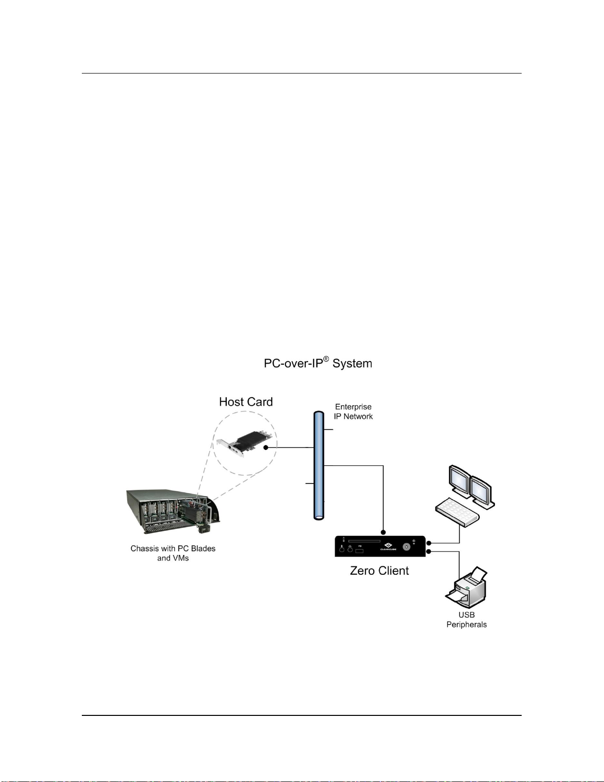
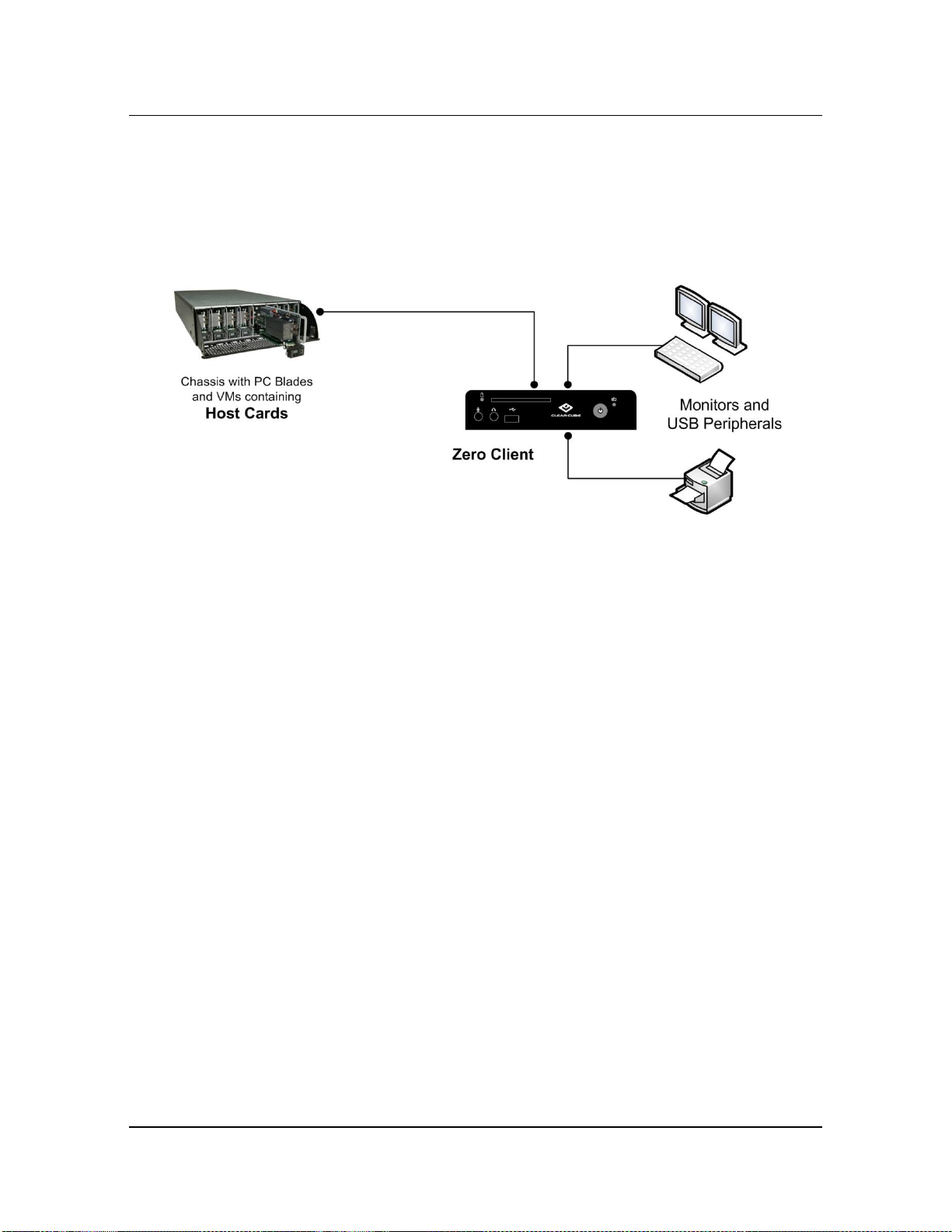
PCoIP technology is delivered in hardware and software implementations, including desktop zero
clients and TERA host cards, as shown in the following figure.
Figure 1. A logical overview of a zero client and host card using PCoIP technology
2 PCoIP System User’s Guide
Page 10
1.2 Component and Interface Overview
1.2 Component and Interface Overview
In typical deployments, a zero client is connected to a remote computing device (a remote PC,
blade, or virtual machine) by a direct connection or over an IP network. Zero clients use the
PCoIP protocol to connect to a host card in a remote device, which is typically located in a secure
data center. Once connected, the user can use the remote device as if it is a local: the remote blade
or VM desktop is displayed on monitors connected to the zero client, and USB peripherals
connected to the zero client are directed to the remote device.
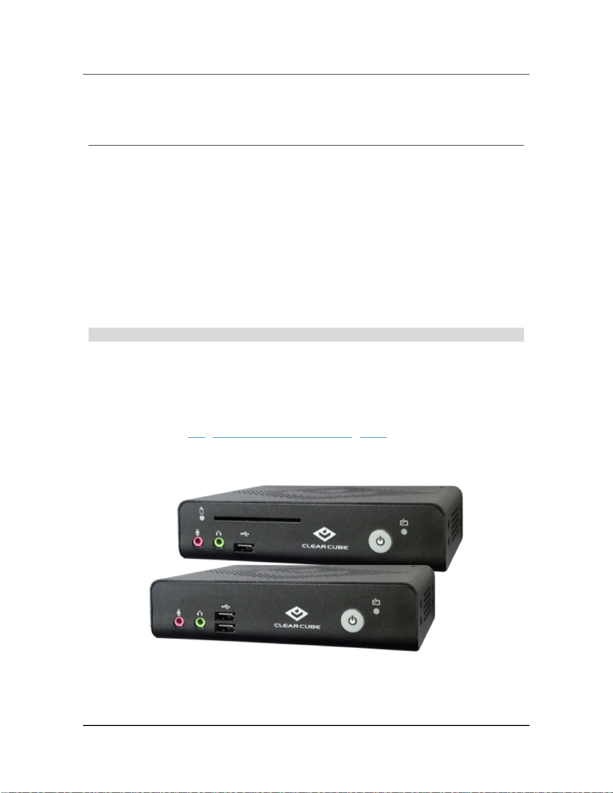
1.2.1 Zero Client
NOTE: The terms zero client and Cloud Desktop are used interchangeably in this document.
A zero client, or Cloud Desktop, is a remote computing device that connects a user’s monitors,
keyboard, mouse, speakers, and other peripherals to a remote ClearCube PC blade (computer) and
to virtual desktops (VMs). As shown above, computing resources are typically located in remote
data centers. Zero clients enable users to work on a blade or VM as if it is a local PC. The
connection between the zero client and the remote device is over PCoIP protocol handled by
PCoIP processors (see1.3 “TERA2 and TERA1 Processors” below). Inside the remote device, a
PCoIP host card manages the PCoIP session.
Figure 2. Zero clients
ClearCube Technology, Inc. 3
Page 11

Chapter 1. Introduction
ClearCube zero clients support multi-head operation, enabling you to specify a different
resolution and display orientation (portrait or landscape) for each monitor.
Zero clients do not require unique OS drivers, and support the following standard peripherals:
Up to four independently–configurable monitors
Keyboards
Mouse and other pointing devices
Audio devices
USB peripherals, including isochronous USB devices and printers (zero client USB ports are
USB-2.0-compatible)
Supporting zero client models provide an integrated CAC/smart card reader and SFP network
modules
You can deploy zero clients on:
Existing Ethernet networks
Secure point-to-point connections (that is, direct connection of zero client and host) to
prevent desktop-display data commingling with other network traffic
For additional detailed specifications for each zero client, see the zero client Quick Start Guide
and datasheets at http://www.clearcube.com/.
4 PCoIP System User’s Guide
Page 12
1.3 TERA2 and TERA1 Processors
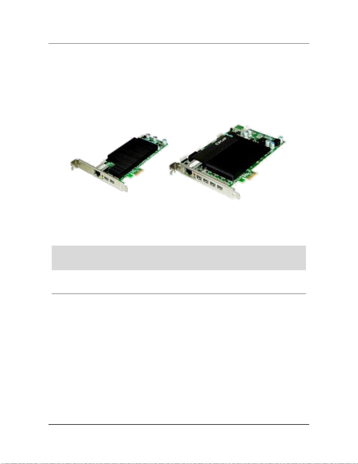
1.2.2 Host Card
A PCIe® card, based on the TERA processor, contained in a computing device (such as a PC
blade or a VM). Host cards enable supported zero clients to connect to using PCoIP technology to
provide high resolution graphics, audio, and video and full USB peripheral support.
Figure 3. Host cards
NOTE: ClearCube recommends always using the same firmware version on zero clients and
host cards. See PCoIP Firmware Compatibility Guide, available on the ClearCube
Support site, for detailed information about PCoIP firmware versions and compatibility.
1.3 TERA2 and TERA1 Processors
PCoIP processors in zero clients and host cards deliver PC video, audio, and USB over an IP
network. TERA processors belong to either the TERA2 (second generation) or TERA1 (first
generation) processor family. For detailed information about device compatibility, see Tech
Bulletin TB00275: TERA1 and TERA2 Device Compatibility on the ClearCube Support site.
The lists below show TERA processor families and the ClearCube devices that use them.
TERA2
Host cards: V5400-series and above
Zero clients: CD7600-series and above
ClearCube Technology, Inc. 5
Page 13

Device
Interface for Configuration and Management
Zero client
Web interface or OSD
Host card
Web interface
Chapter 1. Introduction
TERA1
Host cards: V5300-series and lower
Zero clients:
C7400-series and lower
I9400-series
1.4 Device Interfaces
Host cards and zero clients provide the following interfaces for device configuration and
management:
Web interface
On-screen display (OSD)
The following table shows each device and the interface to use for configuration and
management.
Table 1. Device support for each interface
The following sections show the interfaces and provide references to additional information.
1.4.1 Web Interface
Use the Web interface, shown in the following figure, to configure, manage sessions, and more
for any host card or zero client.
6 PCoIP System User’s Guide
Page 14
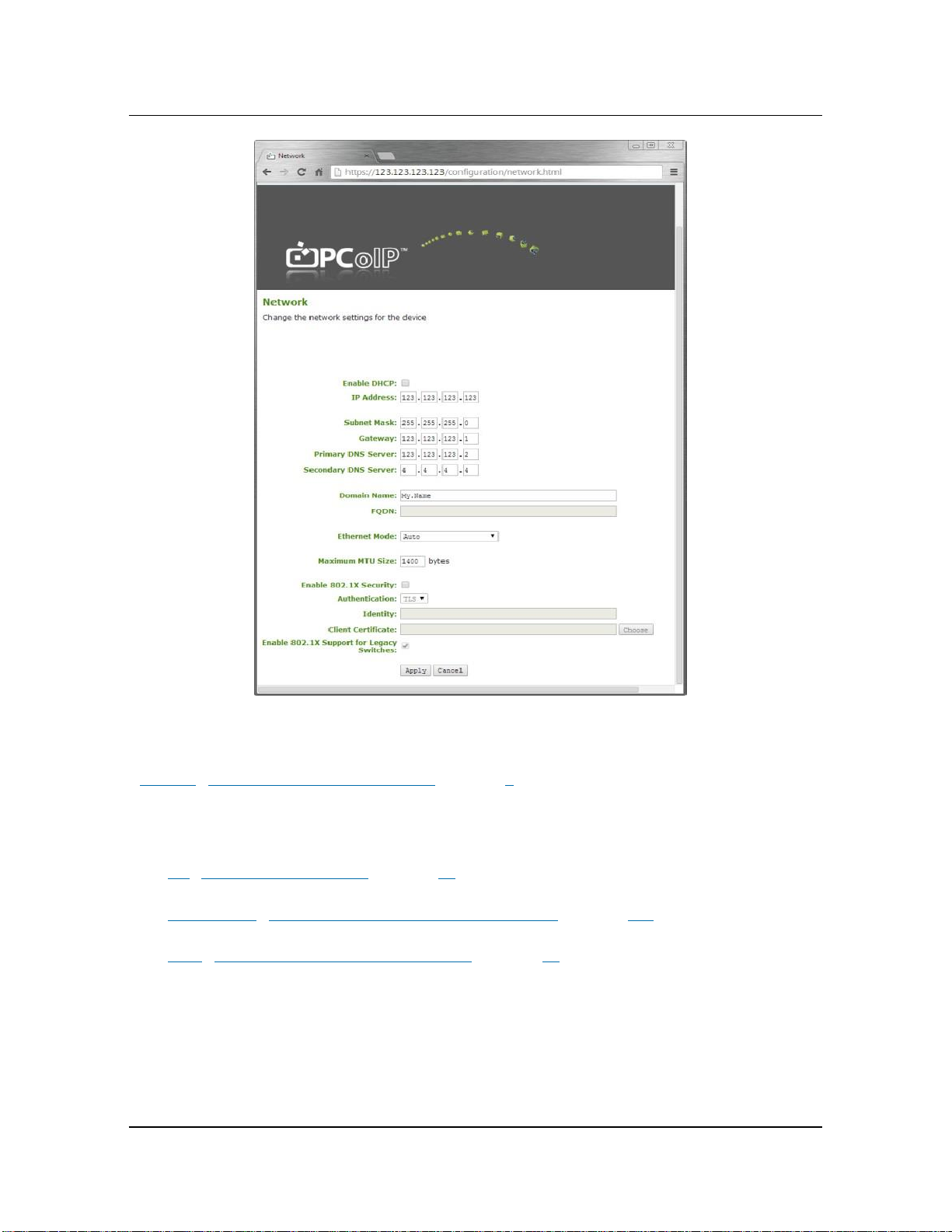
1.4 Device Interfaces
Figure 4. The Web interface’s Network page displayed in a browser
Table 1. “Device support for each interface” on page 6 shows each device and the interfaces you
can use to configure them.
For additional information:
6.3 “Using the Web Interface” on page 63
Appendix D: “Zero Client and Host Card Web Interfaces” on page 118
6.8.1 “Session Control and Peer Information” on page 88
ClearCube Technology, Inc. 7
Page 15
Term
Description
A6106D
This ClearCube A-series PC blade supports host cards and the full range
of ClearCube zero clients. A61056D blades support Intel® Core i7™ and
Intel Core i5™ processors, and up to ten A6106D blades can fit in an Aseries chassis.
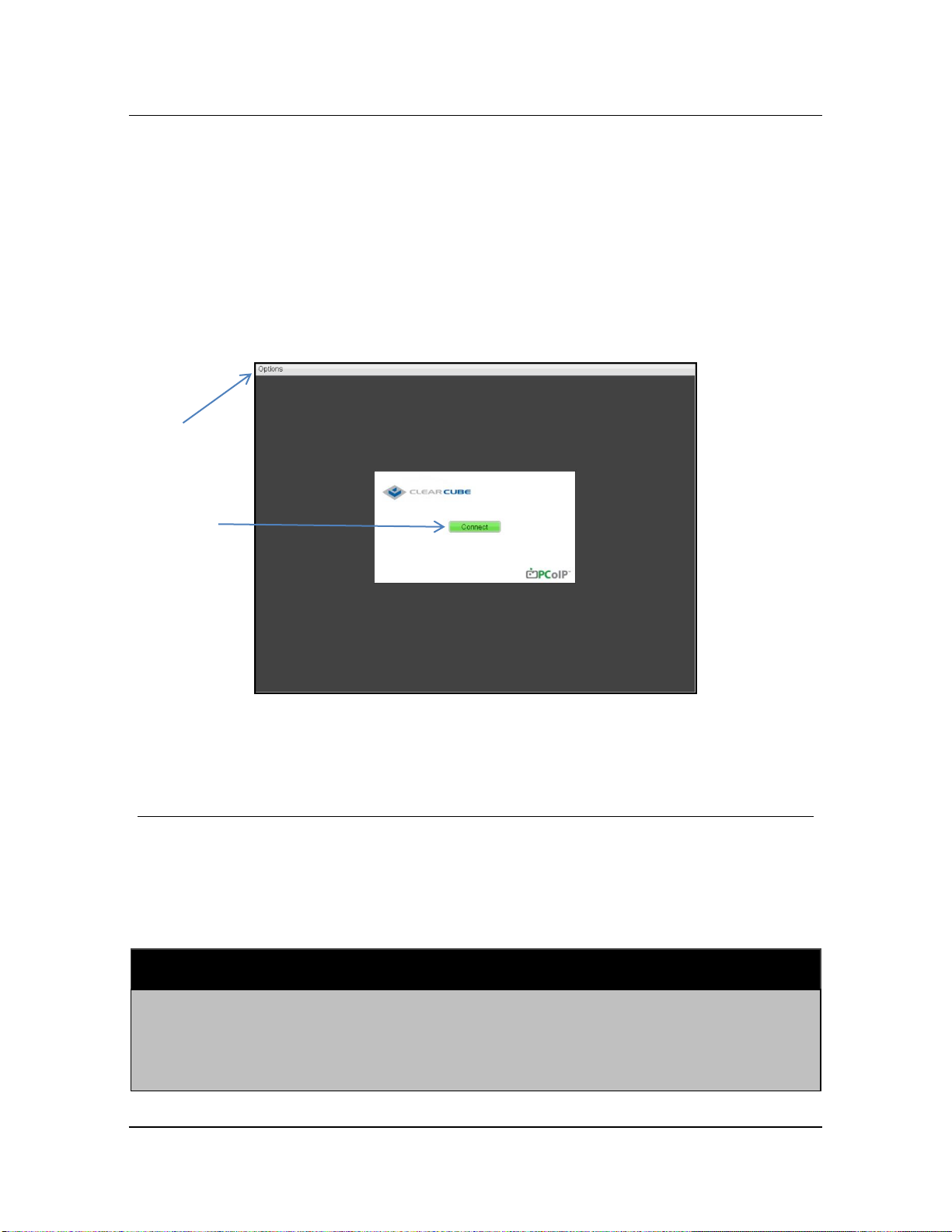
Options
Menu
Connect
Button
Chapter 1. Introduction
1.4.2 On-Screen Display (OSD)
The On Screen Display (OSD) is a local zero client interface that is displayed when a zero client
is powered on and a PCoIP session is not established. Thin client users click the Connect button
(shown below) to connect to a host card.
The OSD provides zero client configuration options, session- and device-related information, and
more. Click the Options menu to display menu options.
Figure 5. On-Screen Display (OSD) and status icons
1.5 Terminology Used in This Guide
The following list describes PCoIP-specific and related terms that are frequently used in this guide.
Table 2. Terms used in this guide
8 PCoIP System User’s Guide
Page 16

Term
Description
A3100
The ClearCube A3100 Chassis houses up to 10 A-series blades in a
secure, rack-mounted, 6U enclosure. The A3100 Chassis provides
chassis management features, cable management, and blade
connectivity. Chassis connectivity includes USB 2.0, two network ports
for each enclosed blade, and PCoIP connections to support zero clients.
Blade
A computer with a typically longer, narrower shape than traditional
computers. Blades are designed to reduce space and energy
requirements and are mounted in a rack (the blade enclosure) that
supplies power, network, USB, and other features for all blades
contained in the rack.
Chassis
Also called a rack, this hardware contains host blades, or computers,
typically in a data center or other location.
CMS
Connection Management Server: an external management tool used to
manage PCoIP hosts and zero clients. Also see Connection broker and
Sentral.
Connection
broker
Software that manages the assignment of computing resources to users.
For example, when a user logs in, a connection broker can always assign
that user to a particular host or to a particular set of hosts. Connection
brokers can also perform additional tasks, such as load balancing,
managing power states of zero clients and hosts, or firmware updates.
Connection
management
server
See Connection broker.
Direct connect
PCoIP host and zero client connection where devices are directly linked
by an Ethernet cable, and are outside of any networks. See Figure 6 on
page 14 for an illustration of a PCoIP deployment using direct
connections.
Dual
A ClearCube zero client supporting two displays, a dual host card, or any
related two-display configuration using PCoIP technology.
Host card
A device on the data center side using PCoIP technology, typically
contained in a PC blade or other computing device.
OSD
On-Screen Display, also called the Connect screen. This is the local
interface for zero clients. You can also change settings on devices using
the Web interface.
1.5 Terminology Used in This Guide
ClearCube Technology, Inc. 9
Page 17

Term
Description
Peer
Each PCoIP device has a corresponding device, or a peer, to which it
connects. For example, if a zero client establishes a PCoIP connection to
a host card, the zero client and host at each end of the session are
peers.
PCoIP
A presentation protocol that enables zero clients and host video cards to
deliver high–performance video, audio and USB data to users. PCoIP
technology consists of dedicated processors on the zero client and on the
host to which the zero client connects.
Quad
A ClearCube zero client supporting four displays, a quad host card, or
any related four-display configuration using PCoIP technology.
R3040S
A dual-width ClearCube blade with dual Intel® Xeon® Quad-core
processors, up to 4 hard disk drives and hardware RAID support, four
10/100/1000 Ethernet ports, and support for host cards. Up to four
R3040S blades can fit in a ClearCube R4300 chassis.
R3082D
A ClearCube blade with Intel Core i3, Core i5, and Core i7 processors,
two 10/100/1000 Ethernet ports, and support for ClearCube dual and tri
(triple-monitor) host cards. Up to eight R3082D blades can fit in a
ClearCube R4300 chassis.
R4300
The ClearCube R4300-series chassis provides all the connectivity and
management features necessary to house ClearCube R-series PC
blades. When combined with ClearCube Sentral management software,
the chassis delivers unique capabilities such as hot sparing, blade
switching, hardware remote control, and out-of-band blade management.
The chassis is based on a modular, redundant architecture that can be
configured to optimally support ClearCube C/Ports, I/Ports or both. The
R4300 can contain up to eight single-slot blades (such as the R3082D)
and four dual-slot blades (such as the R3040S).
Sentral
ClearCube Sentral is a connection broker that enables IT administrators
to manage remote computing environments. Sentral can optimize
hardware utilization by dynamically allocating zero clients to a defined
pool of hosts (computers). Alternatively, administrators can map users to
specific hosts. Automatic zero client and host discovery makes it easy for
administrators to manage computing assets. Administrators can use
Sentral to switch zero client users to a spare host if they experience
device-related issues. See Sentral Administrator’s Guide for more
information.
SLP
Service Location Protocol is a discovery protocol that enables computers
Chapter 1. Introduction
10 PCoIP System User’s Guide
Page 18

Term
Description
to find services. ClearCube devices can use SLP to dynamically discover
zero clients and host cards without information about their location on a
network.
Standard static
A static session on a network.
Static session
Describes a connection between a PCoIP hosts and zero client, where a
device always connects to the same peer (requiring that device IPs do
not change). This can be facilitated by assigning static IP addresses to
devices, or by reserving IP addresses in DHCP environments. In a PCoIP
environment, a static session can be a standard static sessions or a
direct connection.
TERA or Tera
The Teradici application-specific integrated circuit (ASIC) that resides on
the zero client and host devices. In this document, Teradici ASICs are
also called processors and chips. Tera processors families include
TERA1 and TERA2.
Web interface
An interface that enables configuration of all zero client and host
features. Zero clients and host cards use the same Web interface.
Zero client
A small device using PCoIP technology to connect to a device containing
a host card. Zero clients are typically located on a user’s desk and have
displays and peripherals (such as a keyboard and mouse) connected to
them.
1.5 Terminology Used in This Guide
ClearCube Technology, Inc. 11
Page 19

Chapter 2. Connection Modes and
Network Topology
When considering and preparing for your deployment of zero clients and host cards with PCoIP
technology, there are several critical aspects of your deployment to address. This section
identifies and provides a general description of these concepts:
Device management
Peer assignment
IP address assignment
The following sections describe each of these concepts. Consider each to determine how to
address them in your deployment. After making these fundamental decisions, you can choose the
lower-level details of how to deploy devices.
Chapter 6 “Configuring Devices, Setting Peers, and Connecting” on page 55 details each
deployment methodology and provides step-by-step instructions about how to implement each
part of the deployment methodologies introduced in this chapter.
2.1 Device Management and Peer Assignment Options
You can use tools to manage connections between zero clients and hosts or leave devices
unmanaged, as described below.
Managed Environment—Managed environments use management consoles and connection
brokers (such as ClearCube Sentral®), which enable you to maintain allocations between zero
12
Page 20

2.2 Peer Assignment
clients, hosts, and users. Connection brokers dynamically issue peer assignments based on
device- and user-based settings within the connection broker. Sentral enables administrators
to update device firmware, configure devices, manage chassis, mange device power states,
generate reports, perform event logging, and much more.
Unmanaged Environment—Unmanaged environments require connections based on
static, pre-established peers or, for installations of ten seats or less, discovering peer
devices using Service Location Protocol (SLP). In an unmanaged environment, you can
set peer assignments using:
Static assignments—In a static assignment, a zero client always connects to the same
peer, or host card, using a static IP address or a reserved DHCP address.
Service Location Protocol (SLP)—SLP is a discovery protocol that enables computers to
find services. ClearCube devices can use SLP to dynamically discover other zero clients and
host cards without information about their location on a network. SLP can be useful in
scenarios where users do not need to connect to the same blade (such as in call centers). SLP
discovery returns a maximum of 10 devices, which could be an issue in a large deployment
(though this could be useful in a small deployment). SLP discovery requires routers to
forward multicast traffic between subnets, and this is not permitted in many environments.
2.2 Peer Assignment
PCoIP sessions require peers at each end of the connection: a zero client at one end and a host
card at the other. The following sections describe ways that peers are assigned to each other.
2.2.1 Static Assignment (Direct Connection)
In a direct connection, a zero client and a host (that is, a blade containing a host card) are
connected by a direct cable link. You might use a direct connection if you want to set up a simple
deployment quickly, or in scenarios where it is important to keep PCoIP data and regular network
data separate. Remember that in a direct connection:
Administrators cannot access a device’s Web interface directly or remotely. This prevents
administrators from performing remote configuration or other administrative or maintenance
tasks. In this scenario, administrators can only access a zero client’s On-Screen Display
(OSD), which provides a reduced set of administrative and diagnostic features.
See Appendix D: “Zero Client and Host Card Web Interfaces” on page 118 for a reference to
information about Web interface items.
ClearCube Technology, Inc. 13
Page 21
Chapter 2. Connection Modes and Network Topology
You cannot use device management tools and connection brokers, including Sentral, which
require network access.
The picture below shows a PCoIP deployment using direct connections.
Figure 6. A deployment using direct connections
2.2.2 SLP Discovery
Zero clients and host cards require a peer to create a PCoIP session. Zero clients and host cards
can use Service Location Protocol (SLP) to discover devices to which they can connect. Devices
can use SLP discovery without a CMS management tool. You can use the Web interface’s
Discovery page (shown below) to enable SLP discovery for a device.
14 PCoIP System User’s Guide
Page 22
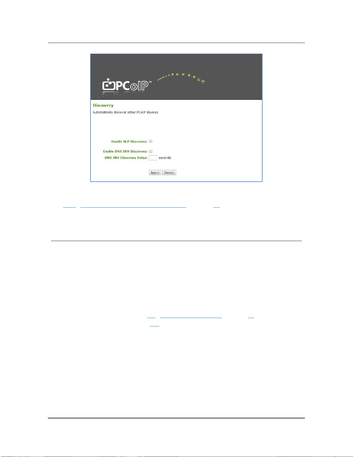
2.3 IP Address Assignment
Figure 7. The Web interface’s Discovery page, where you can enable SLP discovery
See 6.6.4 “Unmanaged DHCP with SLP Discovery” on page 82 for instructions about
enabling SLP discovery.
2.3 IP Address Assignment
The following sections describe the various IP address assignment methods in a PCoIP deployment.
2.3.1 DHCP
ClearCube PCoIP devices are initially configured for DHCP environments through the Web
interface’s Enable DHCP option (see 6.3 “Using the Web Interface” on page 63 for information
about the Web interface, and see page 109 for details about the DHCP option).
ClearCube Technology, Inc. 15
Page 23

Enable DHCP
Chapter 2. Connection Modes and Network Topology
Option
Figure 8. The Enable DHCP Option on the Web interface's network page
When a user powers on a zero client or host, the PCoIP device obtains an IP address from the
network’s DHCP server. If the DHCP server is unavailable at any time while the zero client or
host is already powered on, the zero client keeps its current IP address. The zero client keeps
this IP address until a user powers off the device. If the zero client is powered on when the
DHCP server is unavailable, the zero client uses one of the default, static IP addresses shown in
2.3.3 below.
2.3.2 Reserved IP Addresses Using DHCP
This IP address assignment technique is similar to static IP assignment, where a DHCP server
issues a reserved IP address for a specified MAC address. Using this technique, you can deploy
PCoIP devices in a DHCP environment and use static sessions. In this deployment, a device
obtains an IP address and behaves as described above; this model is configured completely within
the DHCP server.
16 PCoIP System User’s Guide
Page 24
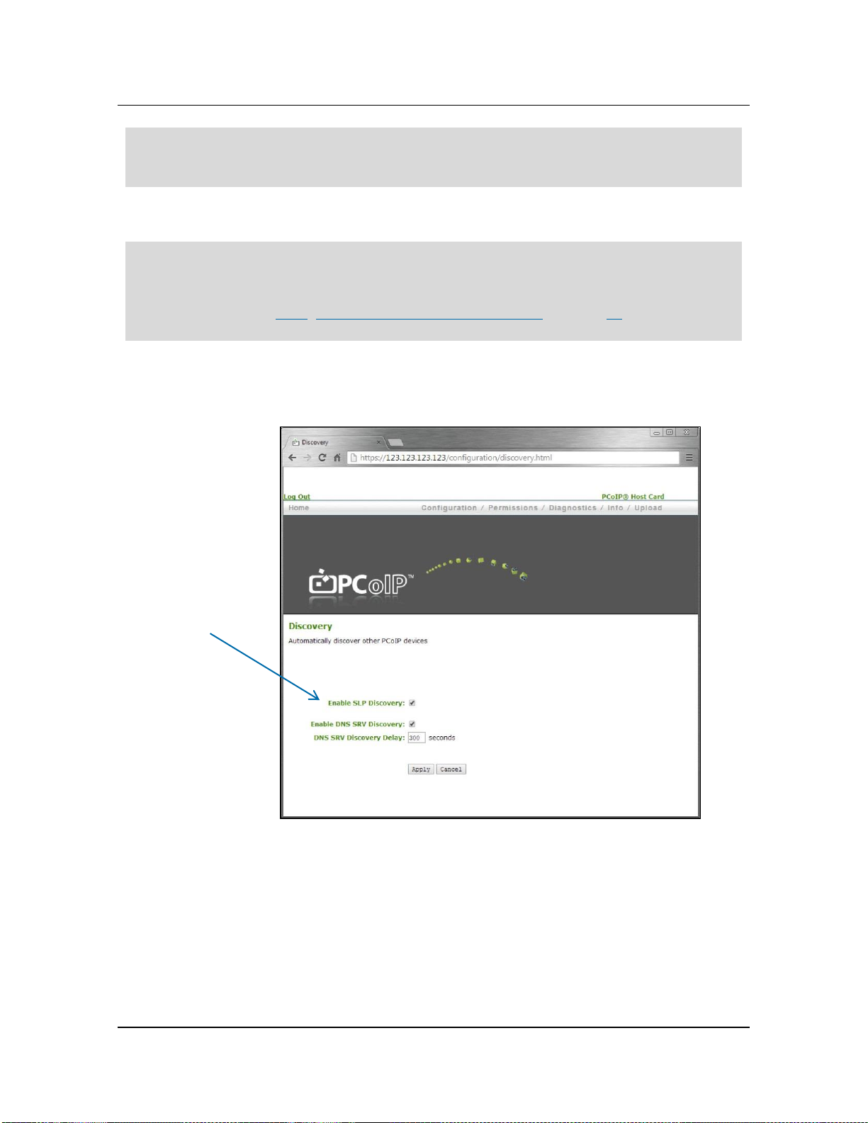
Enable
SLP Discovery
2.3 IP Address Assignment
NOTE: In instances where you are assigning peer devices using reserved DHCP addresses,
device discovery is not appropriate. ClearCube recommends disabling SLP discovery in
deployments using reserved DHCP addresses.
In a managed environment, Sentral must discover the devices to build the Sentral database.
NOTE: If you are using SLP discovery, after you click the Connect button on the zero client’s On-
Screen Display (OSD), the OSD displays a maximum of 10 hosts (blades). Remember
that there might be more PCoIP connections established on your network that are not
displayed. See 6.3.2 “Using the On-Screen Display (OSD)” on page 65 for more
information about the OSD.
The following figure shows the Web interface’s Enable SLP Discovery option on the
Configuration > Discovery page.
Option
Figure 9. Enable SLP Discovery option on the Web interface's Discovery page
ClearCube Technology, Inc. 17
Page 25

Chapter 2. Connection Modes and Network Topology
2.3.3 Static IP
You can use static IPs in any environment—managed or unmanaged. PCoIP devices have default,
fallback static IP addresses. The default, static IP addresses are as follows:
zero client—192.168.1.100
host card—192.168.1.101
Subnet—255.255.255.0
Gateway—192.168.1.1
These default, known addresses ensure that users can move zero clients between networks and
always have a known IP address. See 6.1.5 “Using Default Device Fallback IP Addresses” on
page 61 for more information about default, fallback IP addresses.
2.4 Network Topology
Zero clients and host cards communicate over a standard Ethernet connection. You can connect
devices over a network shared with other devices or directly over a dedicated connection. The
network in your deployment can generally be:
Shared—In typical deployments, devices are connected to a shared network. This topology
provides the following benefits:
Each device’s Web interface is accessible from other computers on the network.
Administrators can use management tools and connection brokers (ClearCube Sentral) to
manage devices
Direct—A direct connection can be useful for first-time users to experiment with or test a
zero client and host card. Highly secure deployments that require the isolation of PCoIP
traffic might find direct connections or a set of direction connections useful. Direct
connections can prevent administrators from accessing the devices’ Web interface unless they
connect a laptop to the host. Otherwise, administrators must use the device’s On-Screen
Display (OSD), which provides a limited set of administrative capabilities.
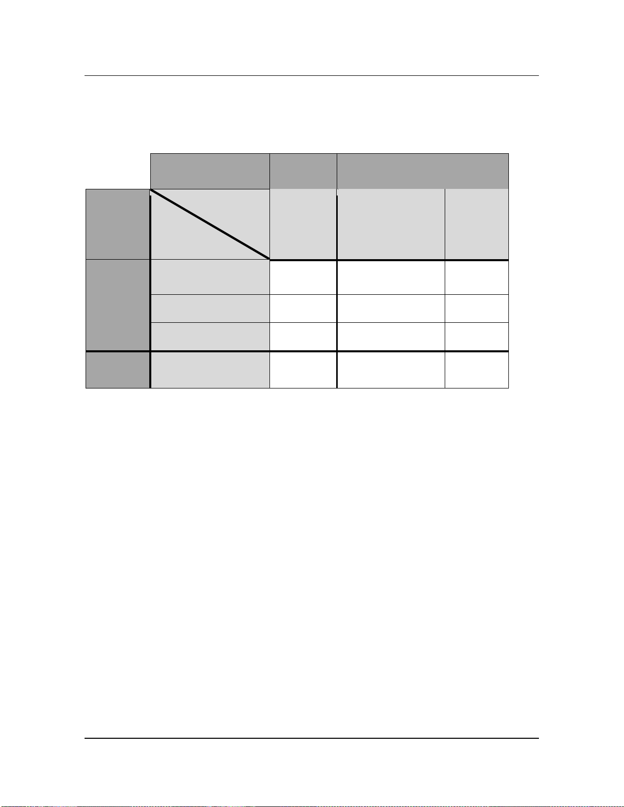
As discussed at the beginning of this chapter, the primary categorization of your deployment
includes device management and network topology. Additional aspects include peer assignment
and IP address assignment. The following table shows the PCoIP connection methodologies
discussed in this document and the corresponding ways that devices obtain IP addresses in each
18 PCoIP System User’s Guide
Page 26
Management
Managed
Environment
Unmanaged
Environment
Network
Topology
Peer Assignment
IP Assignment
CMS
Assignment
SLP
Discovery
Static
Assignment
Shared
DHCP
×
Reserved DHCP
Static IP
Direct
Connection
Static IP
×
2.4 Network Topology
method. A check mark () indicates that you can use an IP address assignment technique in an
environment, and an X indicates that you cannot use a technique in the environment.
Table 3. PCoIP connection methods
As noted previously, each deployment method detailed in this table is discussed in detail in
subsequent chapters. Detailed instructions about how to implement each aspect are provided. This
table accompanies each section to illustrate the technique being discussed.
ClearCube Technology, Inc. 19
Page 27

Chapter 3. Network Considerations
This chapter shows network-related items to consider when preparing for deployment and shows
settings to configure for optimal network performance. The focus is on network bandwidth and
zero client and host card settings that you can configure. Additional topics include a brief note
about network architecture and the ports and protocols that devices use.
See PCoIP Protocol Network Design Checklist (TER1105004) at techsupport.teradici.com/ for
additional information.
3.1 Important Device Configuration Steps
There are several important network-related settings required for deployment that can vary
depending on the zero clients, host cards, and network devices in your deployment. See
4.4 “Mandatory Network-Related Settings” on page 39 for instructions about configuring devices.
3.2 Overview and Terms
There are a variety of network configurations that can impact the performance of devices using
PCoIP technology. This section describes how a network impacts user experience through system
responsiveness, steaming video quality, and device interaction. In this document, limits are
defined by the two major network metrics: bandwidth and latency.
The list below defines terms used in this chapter.
Latency
The time it takes a packet to travel from one device to a destination device.
20
Page 28

No effect
Notice effect
Usable
3.2 Overview and Terms
Bandwidth
The capacity of the network, or the quantity of bits per second that can travel through the
transfer medium.
Round-trip latency
The time it takes a packet to travel from one device to a destination and the reply to come
back to the original host. For example, the ping command measures round-trip latency.
Bridge
A network device used to transparently connect two sides of the same network. The two
network halves that run through the bridge appear as the same network.
Router
A network device used to connect two different networks. Each side of the router appears as
two different networks.
Latency and bandwidth affect usability; however, they are not cumulative in nature for keyboard,
video, and mouse activities. Latency and bandwidth significantly affect file transfers from USB
mass storage devices.
Latency: ClearCube tests show that the average number before users begin noticing delay is just
over 17 milliseconds (35 milliseconds round trip), though users consider systems usable at over
25 milliseconds (50 milliseconds round trip).
Bandwidth: For video performance the following performance characteristics can be seen.
Figure 10. Bandwidth effect on user experience
For strict 2D text or still image applications, bandwidth as low as 3 Mbps is acceptable.
Network bandwidth and latency in your environment can result in users perception issues in the
following areas:
ClearCube Technology, Inc. 21
Page 29

Chapter 3. Network Considerations
Screen updates
Mouse and keyboard responsiveness
Video streaming quality including pixilation and blocking
Mass storage (USB thumb drive) responsiveness
3.3 User Experience
Figure 11. Latency and user experience
The figure above shows that acceptable performance is around 17 milliseconds latency (34
milliseconds round trip). The point where users can perceive a delay is 12 milliseconds (24
milliseconds round trip).
At 35 milliseconds, users will like have difficulty controlling mouse devices. Slowing down the
mouse tracking rate can help.
For video performance, the limit at which latency has an effect is around 200 milliseconds.
Latency: Under 20 milliseconds, users should not notice performance degradation. When latency
rises above 20 milliseconds, users typically notice latency. User typically find a latency of 35
milliseconds unacceptable.
22 PCoIP System User’s Guide
Page 30
3.4 Bandwidth Effects on Usability
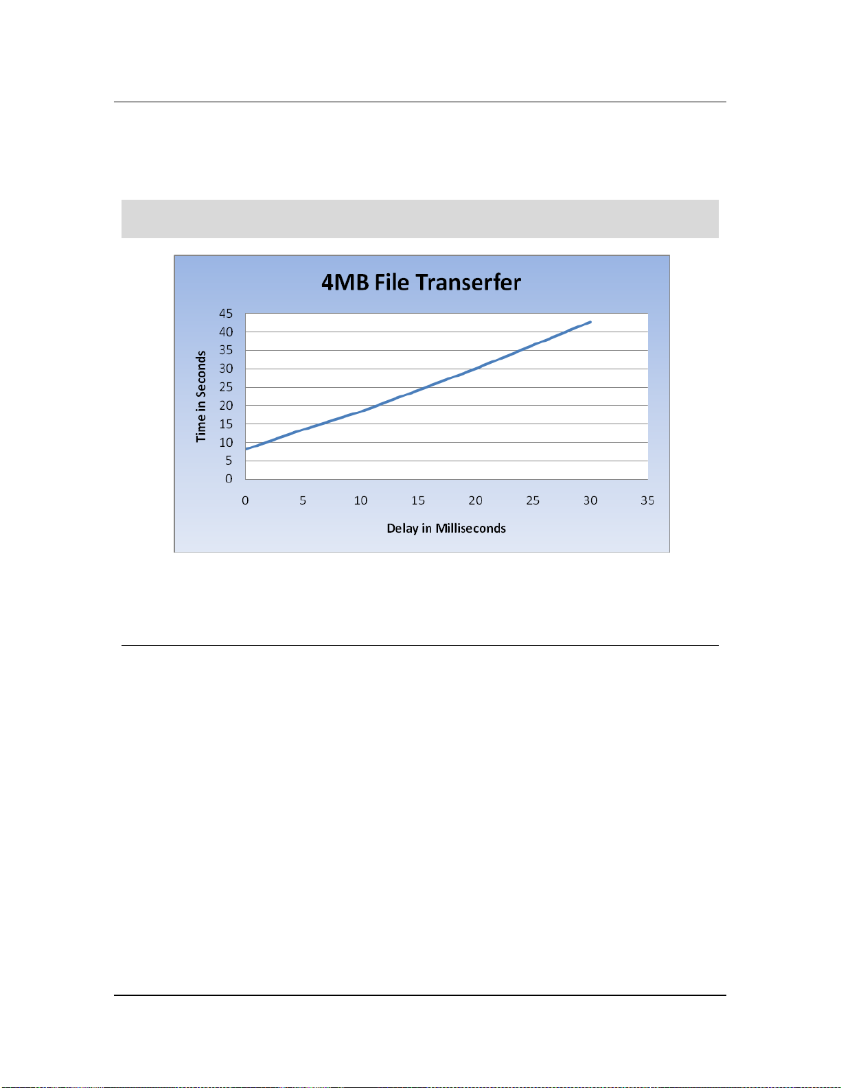
Non-interactive usage: For USB devices, increased latency nearly linearly affects the
performance of the device. For example, in the figure below, transferring a 4-MB file to a USB
drive, the following numbers can be seen by stepping through latency increases.
NOTE: Although WAN acceleration products cannot affect the video portion of PCoIP traffic, they
can optimize and improve USB performance.
Figure 12. Latency affecting transfer speed
3.4 Bandwidth Effects on Usability
PCoIP bandwidth issues can cause image quality loss and frame loss.
The higher the bandwidth is in your environment, the better the performance of your PCoIP
devices. Note that PCoIP systems perform well when performing complex tasks in environments
with lower bandwidths. The key to determining system usability is
identifying how sensitive users are to Windows desktop experience settings (for example,
disabling Aero, using only outlines of moving windows, non-animated menus, and so on)
temporary blurring for rapidly-moving items, and
pixilation of moving items when many things are happening at the same time.
ClearCube Technology, Inc. 23
Page 31

Chapter 3. Network Considerations
3.5 Typical Bandwidth Usage
In a PCoIP environment, bandwidth consumption is determined by:
Dynamic screen content
Audio
USB traffic
3.5.1 User Types and Bandwidth Consumption
Bandwidth usage in a PCoIP environment primarily depends on the computing tasks that zero
client users perform. Zero client users are generally grouped in the following types.
NOTE: The values shown in the table below represent bandwidth consumption only when a user
is performing work of the specified type. User types can change throughout the day
depending on the activity a user performs at a given time. For example, a power user is
effectively a task user when they check their email—even if a CAD application is
displayed on a second monitor and is waiting for interaction.
Power user
This user typically views static images, various documents types, Adobe® PDF files, streaming
content, and one or multiple high-definition videos; runs Windows Explorer, one or multiple Web
browsers, and three-dimensional, visual applications; and creates significant USB traffic using a
mouse, keyboard, and other peripherals such as flash drives.
Basic power user
This user typically views static images, various documents types, Adobe PDF files, streaming
Knowledge user
This user typically views static images, various documents types, Adobe PDF files, and streaming
video; receives streaming audio; runs Windows Explorer and one or multiple Web browsers; and
creates significant USB traffic using a mouse, keyboard, and other peripherals such as flash
drives. Power users’ activity levels can frequently drop to this range, and task users can
occasionally reach this activity level.
Task user
This user typically views static images, word processing documents, and Adobe PDF files, runs
Windows Explorer and one or multiple Web browsers. This level of user activity typically is
equivalent to the idle state of power and knowledge users.
The table below shows each PCoIP user type and the average and peak bandwidth consumption.
24 PCoIP System User’s Guide
Page 32

User Type
Average Bandwidth
Peak Bandwidth
Task
150 Kbps
1 Mbps
Knowledge
600 Kbps
5 Mbps
Basic power
3 Mbps
10 Mbps
Power
7 Mbps
30 Mbps
3.6 Bandwidth Limiting
NOTE: The values shown below represent bandwidth consumption only when a user is
performing work of the specified type. User types can change throughout the day
depending on the activity a user performs at a given time. For example, a power user is
effectively a task user when they check their email—even if a CAD application is
displayed on a second monitor and is waiting for interaction.
Table 4. Typical bandwidth usage
3.5.2 Limiting Screen Saver Bandwidth Consumption
ClearCube recommends reducing unnecessary network bandwidth consumption by limiting the
options available in screen savers or by restricting screen saver use. For example, the Bubbles
screen saver included in many Windows operating systems running at the highest screen
resolutions consumes nearly 10 Mbps. This screen saver’s bandwidth usage can be significantly
higher than what a typical knowledge user consumes. The recommended setting for screen savers
is either blank or none.
3.6 Bandwidth Limiting
Use the Web interface Bandwidth page, shown in the figure below, to limit zero clients and host
card bandwidth for a PCoIP session. The parameters are applied after you click Apply.
To configure the bandwidth used with a VMware View virtual desktop, adjust the PCoIP GPO
session variables.
ClearCube Technology, Inc. 25
Page 33

Chapter 3. Network Considerations
Figure 13. The Web interface Bandwidth page
3.6.1 Device Bandwidth Limit
This field defines the maximum bandwidth peak for the PCoIP system. The bandwidth setting
defines the bandwidth based on which side is sending data:
On the host side: from the host to the client (e.g., graphics data)
On the client side: from the client to the host (e.g., USB data)
The usable range of the device bandwidth is 1000 to 220,000 kbps.
The PCoIP processor only uses the required bandwidth up to the Device Bandwidth Limit
maximum. The processor dynamically adjusts the bandwidth in response to network congestion.
26 PCoIP System User’s Guide
Page 34

3.6 Bandwidth Limiting
Setting Device Bandwidth Limit to 0 configures the PCoIP processor to adjust the bandwidth
depending on network congestion. If there is no congestion, there is no limit on bandwidth. That
is, the processor uses the maximum rate available.
We recommend setting this field to the limit of the network connected to the client and host.
NOTE: The setting in this field is applied immediately after you click Apply.
3.6.2 Device Bandwidth Target
The Device Bandwidth Target value defines the soft limit on the network bandwidth during
periods of congestion (packet loss). When network activity is high, the device bandwidth is
reduced rapidly to the target value and more slowly below this value. This behavior provides an
even distribution of bandwidth between users sharing a congested network link.
After congestion is alleviated, bandwidth use increases depending on the available network
resources up to the specified Device Bandwidth Limit.
Administrators should have a good understanding of the network topology before setting this to a
non-zero value.
The value you specify here is applied the next time a new session starts after you click Apply.
3.6.3 Device Bandwidth Floor
This setting enables you to configure the bandwidth floor used by the firmware when congestion
is present and when bandwidth is required. This lets you optimize performance for a network with
understood congestion or packet loss. If the bandwidth is not required, the bandwidth used drops
below the floor.
A setting of 0 lets the firmware reduce bandwidth to 1000 kbps for these network impairments. Be
sure to have a good understanding of your network topology before setting this to a non-zero value.
NOTE: The firmware implements a Slow Start Algorithm that:
increases the bandwidth used until the bandwidth required is reached, network
congestion is detected, or the Device Bandwidth Limit is reached
begins at the lesser of the Device Bandwidth Limit and 8000 kbps
increases the bandwidth used within seconds
allows a graceful session startup for low bandwidth scenarios (for example, WAN)
After initiating a PCoIP session, users may temporarily notice low bandwidth video artifacts as
the algorithm increases bandwidth usage.
ClearCube Technology, Inc. 27
Page 35

Field
Description
Use Client Image Settings
This field is only available from the host.
When enabled: Image settings on this page are not editable.
The settings that appear (grayed out) are those stored for the
host in flash memory.
When disabled: You can change image settings and
changes are applied to any current sessions.
Minimum Image Quality
This setting enables compromise between image quality and
frame rate when network bandwidth is limited. Some use
cases may require lower quality images at a higher frame rate
while others need higher quality images at a lower frame rate.
In environments where the network bandwidth is constrained,
Chapter 3. Network Considerations
3.6.4 Image Quality
The Image page enables you to adjust the image (graphics) quality of the PCoIP session.
Figure 14. Image configuration page
The table below shows each setting on the Image page.
Table 5. Image page settings
28 PCoIP System User’s Guide
Page 36

Field
Description
moving the slider towards Reduced allows higher frame rates.
Moving the slider towards Perception-Free allows for higher
image quality. When network bandwidth is not constrained,
the PCoIP system maintains perception-free quality
regardless of the Minimum Image Quality parameter.
NOTE: The Minimum Image Quality must be less than or
equal to the Maximum Initial Image Quality. It does not have a
corresponding parameter on the OSD as it is an administratoronly parameter.
Maximum Initial Image
Quality
Use the slider to reduce the network bandwidth peaks caused
by screen content changes. This parameter limits the initial
quality on the first display frame of a screen change.
Unchanged regions of the image are built to a lossless state
regardless of this parameter.
NOTE: The Maximum Image Quality:
must be greater than or equal to the Minimum Image Quality
does not have a corresponding parameter on the OSD as it is
an administrator-only parameter
Image Quality Preference
Use the slider to set if you want the image to favor image
sharpness versus smooth motion during a PCoIP session
when network bandwidth is limited.
NOTE: This field is also accessible on the host if the PCoIP
Host Software is installed. The slider appears in the host
software’s Image tab. This setting does not work in PCoIP
sessions with VMware View virtual desktops running release 5.0
or earlier.
Maximum Frame Rate
The maximum frame rate helps you manage multiple PCoIP
sessions over a single network link. This setting determines
the limit that your users can reach. Set this field to 0 to set no
frame limit. If you set a value, a single user is limited to that
value. This helps to control the user experience for all your
users.
NOTE: The Maximum Frame Rate does not have a
corresponding parameter on the OSD as it is an administrator-
3.6 Bandwidth Limiting
ClearCube Technology, Inc. 29
Page 37

Field
Description
only parameter. This setting does not work in PCoIP sessions
with VMware View virtual desktops running release 5.0 or
earlier.
Disable Build to Lossless
Leave this field unchecked to retain build to lossless. In these
cases, the images continue to be built to a lossless state.
This is the default (recommended) setting.
WARNING: Enabling the Disable Build to Lossless feature will
degrade the image presented to zero client users. Do not
activate the Disable Build to Lossless feature unless zero
client administrators have determined that users do not require
optimal image quality to perform critical functions. It is the sole
responsibility of the zero client administrator to make this
determination.
If you choose to disable build to lossless, PCoIP rapidly
builds the client image to a high quality, perceptually lossless
image. If you enable build to lossless, if the image remains
constant, PCoIP continues to refine the image in the
background until it reaches a fully lossless state. Stopping the
build process when the image reaches the perceptually
lossless stage can deliver significant bandwidth savings. If
you have any questions about this field setting, contact
ClearCube Support.
NOTE: There is no Disable Build to Lossless setting on the
OSD as it is an administrator-only parameter. This setting does
not work in PCoIP sessions with VMware View virtual desktops
running release 5.0 or earlier.
Chapter 3. Network Considerations
3.7 Network Separation
If zero clients and host cards are on a shared production network, PCoIP traffic might slow
network traffic. If you experience bandwidth issues after addressing typical network issues that
are discussed in this chapter, you might consider separating PCoIP traffic and regular Enterprise
network traffic.
30 PCoIP System User’s Guide
Page 38

Interface
Protocols
Port(s)
Encrypted
Authenticated
Purpose
IP Network
DHCP
67, 68
(UDP)
n/a
n/a
Dynamic IP address.
SLP
Discovery
(optional)
SLP
427
(TCP/UDP)
No
No
Discover hosts (unmanaged)
and discovery advertisements
to CMS (managed).
DNS based
discovery
(optional)
DHCP
67, 68
(UDP)
n/a
n/a
Discovery advertisements to
CMS. DHCP options 12 and
15 required (to obtain domain
name).
DNS
53
(UDP)
n/a
n/a
Used to lookup IP address of
CMS FQDN (based on wellknown DNS based discovery
prefix).
HTTPS/SOAP/XML
(TCP with SSL/TLS)
50000
(TCP)
Yes
Yes
Advertisement context uses
Connection Management
Interface (CMS).
DNS SRV
discovery
(optional)
DHCP
67, 68
(UDP)
n/a
n/a
Discovery advertisements to
CMS. DHCP options 12 and
15 required (to obtain domain
name).
DNS
53
(UDP)
n/a
n/a
Used to query the DNS SRV
Resource Record (RR)
HTTPS/SOAP/XML
(TCP with SSL/TLS)
50000
(TCP)
Yes
Yes
Advertisement context uses
Connection Management
Interface (CMS).
Web
Interface
(optional)
HTTPS
(TCP with TLS/SSL)
443
(TCP)
Yes
Yes
Remote web client access
TERA1100/1200 configuration
parameters
HTTP
80
(TCP)
No
No
Redirects to HTTPS.
3.8 Port and Protocol Requirements
3.8 Port and Protocol Requirements
The following table details ports used in deployments using PCoIP technology. The table
indicates in the Interface column if the open ports are required or are optional.
Table 6. Ports and protocols
ClearCube Technology, Inc. 31
Page 39

Interface
Protocols
Port(s)
Encrypted
Authenticated
Purpose
CMI
HTTPS/SOAP/XML
(TCP with SSL/TLS)
50000
(TCP)
Yes
Yes
Connection Management
Interface (CMS)
DNS
53
(UDP)
n/a
n/a
Used to lookup IP address of
CMS (if FQDN specified).
Firmware
Update
(CMI proxy)
FTP
Configurable
(TCP/UDP)
No
No
Obtains encrypted firmware
binary image file from
specified FTP server.
Inter-peer
media
IPSec-ESP
n/a
Yes
Yes
Media traffic channel
(USB/audio/video) between
TERA1100 and TERA1200. IP
protocol 50 per RFC.
Inter-peer
control
TCP with SSL/TLS
8000
(TCP)
Yes
Mutual
authentication
using X.509
certificates
TERA1100 and TERA1200
media control channel.
HTTPS/SOAP/XML
(TCP with SSL/TLS)
50001
(TCP)
Yes
Mutual
authentication
using X.509
certificates
TERA1100 and TERA1200
power management control
channel.
RDP
TCP
3389
(configurable)
Terminal
Server
dependent
No
RDP sessions only (not
applicable to PCoIP
operation).
Time of Day
(optional)
UDP
123
(configurable)
No
No
Network Time Protocol (NTP)
interface.
Chapter 3. Network Considerations
NOTE: See 4.4.1 “Mandatory Network-Related Settings” on page 39 for information about
32 PCoIP System User’s Guide
switch configuration.
Page 40

Chapter 4. Initial Setup
4.1 Caution Statements
Improper connection, mounting, or use of this product could result in component failure or
undesired interference. Read the following caution statements before setting up and operating
zero clients.
Do not connect to AC power until all other connections are made, including the power
adapter. Connecting or disconnecting components or equipment on the back panel when the
zero client is receiving AC power can cause power surges and damage the device.
Do not force a connector into a socket. If any undue resistance is encountered, ensure that the
connector is correctly oriented to the receptacle.
Do not attach a zero client to a telephone jack or other powered network connection. This will
permanently damage zero clients. This damage is not covered under the ClearCube
Technology, Inc. limited warranty.
Allow sufficient space around zero clients for ventilation. Do not place the device in any
enclosure that restricts airflow around the device. Do not place any objects on the device.
To ensure regulatory compliance, use only the power supply included in the shipping carton
with the zero client, or a ClearCube-approved equivalent.
Surge protectors for electrical devices are recommended in areas of frequent lightning.
However, when lightning is occurring, your equipment should be properly shut down and
unplugged from AC power until the storm has passed.
Ensure that you do not interrupt power while zero clients receive firmware updates.
The following sections describe how to set up and mount a zero client.
33
Page 41

4” minimum
4”
min
Front
4”
min
Horizontal Mounting (Overhead View)
4” minimum
4”
min
4”
min
Horizontal Mounting (Side View)
Chapter 4. Initial Setup
4.2 Mandatory Mounting, Cooling, and Airflow Provisions
This section describes important provisions to ensure that there is adequate and proper airflow
and cooling for zero clients.
4.2.1 Ensuring Adequate Clearance around Zero Clients
Ensure that there is at least 4 inches of space around and above zero clients.
4.2.2 Ensuring Proper Client Mounting
You can mount zero clients:
Using a ClearCube VESA mounting bracket to mount a zero client on the rear of a monitor or
under a desk.
On top of a desk or other open, horizontal surface
34 PCoIP System User’s Guide
Figure 15. Minimum clearance around zero client
Page 42

Ensure that a device mounted
Overhead View of Desk with Zero
4.2 Mandatory Mounting, Cooling, and Airflow Provisions
4.2.2.1 Desktop Mounting
When placing a zero client on top of a desk or other flat, unenclosed surface, ensure that:
The open vent faces up (as described in the following section)
There is at least 4 inches of space around edges of the zero client.
There is open space above the zero client.
You do not stack any objects on top of the zero client, including any paper or USB
peripherals (such as hard drives).
Ambient temperature never exceeds 35° C, including in enclosed environments that can
elevate temperatures, such as under a desk, on a shelf, or inside a drawer.
Zero client vents are flat—not standing vertically—as shown in the following figure.
The zero client is not in any enclosed areas, such as:
A desk drawer
A cable tray in a desk
Adjacent walls and furniture, such as file drawers, desk supports, and chairs, do not block or
enclose any sides of the zero client.
under a desk is not adjacent to a
wall. This configuration prevents
proper air flow and cooling.
Client Mounted Adjacent to Wall
ClearCube Technology, Inc. 35
Figure 16. Adjacent wall restricting airflow around zero client
Page 43

Open Vent Facing Up
Chapter 4. Initial Setup
4.2.2.2 Horizontal Mounting: Open Vents Must Face Up
ClearCube zero clients are typically mounted horizontally, as shown below. TERA1-based zero
clients have diamond-shaped vents on both sides, and TERA2-based zero clients have diamondshaped vents on the top. Open vents reveal the interior of the zero client (the open vent is located
on the top of most zero clients. The closed vent on the bottom of TERA1-based zero clients is
sealed with a grey, metal plate. If you mount your zero client horizontally, or flat on a desk top or
other surface, the open vents should face up to allow proper heat dissipation, as shown below.
Figure 17. Open should face up for horizontal zero client mounting
4.3 Cabling
The following sections show how to set up cabling for different PCoIP device deployments.
NOTE: See 4.4 “Mandatory Network-Related Settings” on page 39 for information about
configuring network switch transmission speed and mode for your PCoIP deployment.
4.3.1 Chassis Cabling Overview
The picture below shows the network cabling in a typical zero client deployment between blades
and an A-series or R-series chassis. In the picture below, PCoIP host card and zero client
communication is optimized by isolating PCoIP traffic on a dedicated network (using physical or
virtual LANs). Cables going to zero clients are connected directly to a network switch and then to
a ClearCube A3100 chassis.
36 PCoIP System User’s Guide
Page 44

4.3 Cabling
Figure 18. Typical network cabling diagram
4.3.2 A-Series Chassis Ports
The picture below shows the rear of the A3100 chassis and the expansion backplane port
assignments.
Connect cables from zero clients to the PCoIP ports on the rear of the chassis
Connect cables for standard blade network traffic to the PRI (primary) and SEC (secondary)
network ports (depending on blade support as noted below).
ClearCube Technology, Inc. 37
Page 45

Ethernet
Dedicated
PCoIP
Ethernet
Ethernet
Dedicated
PCoIP
Unsupported
A6105D Blade
A6106D Blade
Chapter 4. Initial Setup
Figure 19. A3100 chassis backplane network port assignments
4.3.3 R-Series Chassis Ports (Network Module)
The picture below shows the rear of the R4300 chassis and the EP2 Pass-Thru Network Module
port assignments.
Connect cables from zero clients to Secondary ports on the rear of the chassis.
Connect cables for standard blade network traffic to the Primary ports on the rear of the chassis.
38 PCoIP System User’s Guide
Page 46

EP2 Network Module
PCoIP in
Secondary Ports
Blade Data in
Primary Ports
R4300 Chassis
4.4 Mandatory Network-Related Settings
Figure 20. R4300 chassis network port assignments
4.4 Mandatory Network-Related Settings
The following sections describe mandatory network-related requirements for zero clients, host
cards, and network devices in copper and in fiber networks.
ClearCube Technology, Inc. 39
Page 47

Chapter 4. Initial Setup
4.4.1 Copper-Based Devices
In deployments using PCoIP technology, the duplex mode and link speed settings for all
connected devices must be the same. When deploying devices in a copper network, ensure that:
You set all devices to auto-negotiate (zero clients, host cards, and other network devices such
as switchers, media converters, and so on). Instructions for zero clients and host cards are
provided below. Consult your network device documentation for instructions about
configuring network devices in your deployment.
All devices operate in full-duplex mode (that is, no devices are set to half-duplex).
CAUTION: If you set any device or device port to a specific duplex mode or link speed, you must
explicitly specify the same settings on any zero client or host card connecting to that
devices or device port. If these two settings for either link partner are different, this
can cause unsupported behavior including devices set to auto-negotiate operating in
half-duplex mode.
To set Ethernet Mode to Auto (Default)
From the Web interface, ensure that the Ethernet Mode for zero clients and host cards is set to
Auto (see 6.3 “Using the Web Interface” on page 63):
1. Click Options > Configuration.
2. Click Unlock on the lower-left portion of the screen and then click OK to unlock the
interface (by default a password is not required; consult your administrator if a password is set).
3. From the Network tab, click the Ethernet Mode drop-down box and select Auto.
4.4.2 Fiber-Based Devices
This section describes requirements for settings on ClearCube fiber zero clients and media
converters to which they connect.
Fiber zero clients are set to:
Full-duplex mode
Flow control (Link Fault Passthrough) disabled
These settings should be the same on any network switch to which the zero client connects. Check
your switch settings and make any necessary changes. The example configuration below shows
40 PCoIP System User’s Guide
Page 48

4.4 Mandatory Network-Related Settings
how to configure negotiation and flow control settings on Cisco Catalyst® switches to connect with
fiber zero clients.
NOTE: Only TERA1-based devices need to disable auto-negotiation as shown in the example
configuration below. TERA2-based devices do not need to disable auto-negotiation.
NOTE: The configuration below is not applicable to Cisco Nexus® switches.
router# configure terminal
router(config)# interface gigabitethernet 0/1
router(config-if)# no negotiation auto
router(config-if)# flowcontrol send off
router(config-if)# flowcontrol receive off
router(config-if)# end
router#
For more information about Cisco switches, see the following:
Cisco Catalyst switches
“Troubleshooting Cisco Catalyst Switches to NIC Compatibility Issues” on the Cisco Web site:
http://www.cisco.com/en/US/products/hw/switches/ps700/products_tech_note09186a00800a7af0.shtml
Cisco Nexus switches
The previous information does not apply to Cisco Nexus series switches. For information
about Nexus products, see the Nexus Wiki:
http://docwiki.cisco.com/wiki/Cisco_Nexus_7000_Series_NX-OS_Troubleshooting_Guide%2C_Release_4.x
If you use any other manufacturer’s network devices, consult their documentation and support resources:
For information about equivalent operating system commands to disable auto-negotiation and
flow control settings
To address any addition interoperability concerns
4.4.3 Drivers and Requirements
ClearCube operating system images include all drivers appropriate for ClearCube Blade PCs, zero
clients, and thin clients. If you are creating or installing operating system images on ClearCube blades,
ensure that you install drivers for all hardware on the blade or remote clients (for example, drivers for
host GPUs or CAC or smart card readers on zero clients).
ClearCube Technology, Inc. 41
Page 49

Chapter 4. Initial Setup
The list below shows operating systems that Teradici Host Driver Software supports.
Windows 8.1, 64-bit
Windows 7, 32- and 64-bit
Windows Vista, 32- and 64-bit
Windows XP SP2, 32- and 64-bit
Windows Server 2008, Server 2008 R2
Windows Server 2003 (not supported by V5140 host cards)
Linux® is supported but has not been tested. Ensure that the Linux distribution you use
contains drivers that support:
Open Host Controller Interface (OHCI) and Enhanced Host Controller Interface (EHCI)
for USB
Realtek HD audio
GPU drivers if applicable (note that V52x0- and V53x0-series host cards include GPUs
and require GPU drivers).
See the following section for information about requirements when creating your own operating
system images.
4.5 Image Creation Requirements
By default, ClearCube zero clients, host cards, and blades using PCoIP technology contain all
necessary firmware and drivers, and blade operating system images are configured appropriately.
If you are re-imaging a blade or installing a custom image on a ClearCube blade, note that your
blade and devices using PCoIP technology require specific firmware, motherboard chipset
drivers, device drivers, and more.
NOTE: ClearCube devices do not necessarily support every driver for firmware that vendors
provide. To ensure that your devices support drivers and firmware, only use drivers and
PCoIP firmware obtained from ClearCube.
42 PCoIP System User’s Guide
Page 50

4.5 Image Creation Requirements
NOTE: If you are re-imaging a blade or installing a custom image on ClearCube blades, you
must install components in the order listed below. Failure to do so can cause
unsupported behavior.
The following list details items and steps required when imaging and configuring ClearCube
blades that use PCoIP technology. Ensure that you install items and perform steps in the order
listed below.
1. Ensure that you obtain drivers for your blade or VM from the ClearCube Support site at
http://www.clearcube.com/support/. All drivers and downloads mentioned in this procedure
are available on the Support site.
2. Connect to the blade you are imaging. For A-series and R3082D blades, connect a zero client
to the A-series chassis. For all other R-series blades, connect a ClearCube C/Port to the
chassis slot that the blade is in. For information about configuring video for R-series blades,
see Technical Bulletin TB00264, “Video Configuration When Powering on R-Series Blades
for the First Time (OOBE).” From the Support site, select the R-series blade you are imaging.
From the blade’s home page, click Technical Bulletins.
3. Install a Windows operating system.
4. Install the Intel chipset driver appropriate for your blade.
5. Configure PCI Express® power management:
a. Click Start > Control Panel > Hardware and Sound > Power Options.
b. Select any power plan (you must perform this procedure on all power plans) and click
Change Plan Settings > Change advanced power settings to display the Power
Options dialog box.
c. Expand the PCI Express item. From the Link State Power Management drop-down
menu, select Off.
6. Install the Intel network adapter driver appropriate for your blade.
7. Optionally, install an appropriate RAID driver.
8. Optionally, install the Intel AMT driver. Note that AMT support typically requires BIOS-
level configuration.
9. If applicable, install the appropriate video driver:
for blades with a V52x0- or V53x0-series host card, install a video driver for the built-in
GPU on the host card.
ClearCube Technology, Inc. 43
Page 51

Chapter 4. Initial Setup
for blades with a V54x0-series host card and a GPU card, install a driver for the GPU.
10. Optionally, install PCoIP Host Driver Software on the blade or VM containing a host card.
The version of the PCoIP Host Software must match the host card and the zero client
firmware versions.
11. Install drivers for any additional peripherals or hardware.
12. Now connect to a zero client (as described in this guide). Depending on the components in
your zero client, you can optionally install zero-client-specific drivers:
a. Install the Realtek HD Audio driver.
b. Install the DB9 driver if your client has a DB9 port.
c. Install the Common Access Card (CAC) driver if the zero client contains an internal
CAC reader.
4.6 Viewing Pre-OS Video (BIOS Configuration) and USB Input
The following sections describe how to view video output (such as power-on self test [POST]
codes and BIOS configuration utility screens) generated before a blade or VM operating system
starts. Instructions are provided for A- and R-series blades.
4.6.1 A-Series Blades
In the A-series architecture, host cards using PCoIP technology do not support local video at the
blade, and USB is redirected to the client after the operating system starts. To access blade preOS video (such as BIOS configuration screens), connect a keyboard to the blade and use a zero
client to view pre-OS video as described below.
44 PCoIP System User’s Guide
Page 52

4.6 Viewing Pre-OS Video (BIOS Configuration) and USB Input
NOTE: These instructions assume that devices are connected to an imaging network or other
network with a DHCP server to provide IP addresses for the blade’s PCoIP host card and
for the zero client. MAC addresses are specified on labels on the side of the blade and on
the zero client. To identify the blade host card to connect to from the zero client, you
might need to consult DHCP tables. DHCP tables should show each device’s MAC address
and the corresponding IP address assigned to the host card and to the zero client.
1. Be sure to have the following:
Ethernet cables, zero client power supply, and a ClearCube zero client compatible with
the blade’s video configuration. The blade’s video configuration is specified on a label on
the side of the blade.
A switch connected to your DHCP network.
A USB keyboard and mouse.
Monitors and monitor power cables.
Computer power cable shipped with your blade.
2. Remove the blade from the chassis. Place the blade on a stable surface, such as a bench or on
the top of a desk.
3. Connect a USB keyboard to a port on the top of the blade. (Ensure that you do not disconnect
the Ethernet cable that might be visible from this opening.)
4. Connect your monitor to a zero client as described below. Do not connect a monitor to either
DVI port on the top of the blade.
5. Connect the blade and the zero client to your network:
Connect an Ethernet cable to the blade’s dedicated PCoIP port (the right-most port on the
rear of the blade—this is the top-most port when the blade is resting on a table). Connect
the other end of the cable to a switch connected to your network.
Connect the zero client to the same switch.
Optionally, if you are imaging the blade, connect an Ethernet cable to the left-most
Ethernet port on the rear of the blade and connect the other end of the cable to the switch
(see 4.5 “Image Creation Requirements” on page 42 for information about system
image requirements).
6. Connect monitors and a mouse to the zero client.
ClearCube Technology, Inc. 45
Page 53

Chapter 4. Initial Setup
7. Connect a power cable to the external power connector at the rear of the blade and then plug
the cable into a power outlet. Continue by connecting the power adapter to the zero client and
then plugging the cord into a power outlet.
8. Power on the blade and then the zero client by pressing the power button on the front of
each device.
9. From the monitors connected to the zero client, click the Connect button. After several
moments, the zero client will identify host cards to which it can connect. The zero client OSD
displays one or more host card IP addresses and their corresponding MAC addresses (the
video host card MAC addresses are specified on a label on the side of the blade).
10. Select the blade’s host card from the list and click OK. Then press the Reset button on the
front of the blade (the left-most button on the bottom edge of the blade’s front bezel). Watch
your monitors for pre-OS video (for example, a message to press the F2 key for configuration
screens; depending on the BIOS, the specified key can be different).
11. After performing configuration steps, power off both devices. Remove the blade and zero
client power cables from the power outlets and then remove the cables from each device.
12. Remove all cables and peripherals from both devices.
13. Replace the blade in the chassis.
4.6.2 R-Series Blades
R-series blades provide pre-OS video over PCoIP sessions or over an analog video connection.
4.6.2.1 Using a Zero Client
The sections below show how to view pre-OS video (such as boot screens and BIOS) using a zero
client.
NOTE: These instructions assume that:
host card (blade) and zero client are on the same subnet (such as an imaging network
or other network) with a DHCP server to provide IP addresses for the blade’s PCoIP
host card and zero client. MAC addresses are specified on labels on the side of the
blade and on the zero client. To identify the host card to connect to from the zero client,
you might need to consult DHCP tables. DHCP tables should show each device’s MAC
address and the corresponding IP address assigned to the host card and zero client.
Service Location Protocol (SLP) is permitted on the network.
46 PCoIP System User’s Guide
Page 54

4.6 Viewing Pre-OS Video (BIOS Configuration) and USB Input
Setting up Devices
1. Be sure to have the following:
R-series blade in an R-series chassis. Note the MAC address shown on a label (VIDEO
V5xxx CONFIGURATION) on the side of the blade. This is the MAC address you will
select when connecting from the zero client.
Ethernet cables, zero client power supply, and a ClearCube zero client.
A switch connected to a DHCP network.
A USB keyboard and mouse.
Monitors and monitor power cables.
2. Insert the R-series blade into the chassis.
3. From the rear of the R-series chassis, connect an Ethernet cable to the secondary port that
corresponds with the slot that the blade is in (see the figure below). Connect the other end of
the cable to a network switch on the same subnet as the zero client.
Optionally, if you are imaging the blade, connect an Ethernet cable to the chassis slot’s
primary port and connect the other end of the cable to the imaging network switch.
Figure 21. Networking Module secondary ports for PCoIP connections (rear of chassis)
4. Power on the blade.
5. Connect monitors to the zero client.
ClearCube Technology, Inc. 47
Page 55

Chapter 4. Initial Setup
6. Use an Ethernet cable to connect the zero client to a network switch on the same subnet as the
host card (that is, the subnet that the blade is on).
7. Connect monitors, a mouse, and a keyboard to the zero client.
8. Connect the zero client power adapter to the zero client and then plug the cord into a
power outlet.
Continue by configuring the zero client as shown below.
Configure the Zero Client
1. Press the zero client’s power button to power it on.
2. From the monitors connected to the zero client, click the Connect button. After several
moments, the zero client will discover and identify the host cards to which it can connect by
showing each host card’s IP address and MAC address.
3. Find the host card you are connecting to and record the IP address (the video host card MAC
addresses is specified on a label on the side of the blade).
4. Click the Cancel button to return to the zero client OSD (on screen display).
5. From the OSD menu on the upper-left portion of the screen, click Options > Configuration.
6. Click Unlock (located on the lower-left portion of the screen) and then click OK (the
password is blank empty by default).
7. Click the Session tab. From the Connection Type drop-down menu, select Direct to Host.
8. Enter the host card’s IP address that you recorded previously.
9. Click Apply in the lower-right portion of the screen, and then click OK. You are returned to
the OSD screen.
You can now connect to the host card as described below.
Connect to the Host Card
1. From the OSD, click Connect. After several moments, the zero client connects to the blade’s
host card and displays the OS login screen or desktop.
2. Press the zero client power button twice to select the Power Off Workstation option on the
zero client pop-up menu. The zero client power button should be green and begin to flash.
48 PCoIP System User’s Guide
Page 56

4.6 Viewing Pre-OS Video (BIOS Configuration) and USB Input
3. Press any key on the keyboard to restart the remote blade. The zero client should display the
message Waiting for host to wakeup, please wait….
4. Press the F2 key several times to enter the BIOS setup utility.
5. Configure your BIOS as appropriate for your environment. After performing BIOS
configuration steps, press F10 to save and exit the BIOS. The blade now boots to the OS.
The zero client is now configured for direct connection to the host card you specified. If
necessary, you can return to the zero client configuration screen and change the session type back
to Direct to Host + SLP. See “Configure the Zero Client” on page 48 for instructions about
changing the connection type from the OSD’s Session tab.
4.6.2.2 Using a ClearCube C/Port (Analog)
The sections below show how to connected a ClearCube analog C/Port to single-slot blades (such
as an R3082D) and to dual-slot blades (such as an R3040S).
Single-slot blades:
When connecting a C/Port to an R-series blade, use the C/Port connector on the Connect
Bay Module that corresponds to the slot that the blade is in (as shown in the following figure, the
Connect Bay Module is located on the rear of the chassis on the far left side). For example, if a
blade is in chassis slot 3, connect your C/Port cable to C/Port connector 3.
You can connect the C/Port while the blade is off and then power it on to see pre-OS video, or
you can connect the C/Port while the blade is powered off and then power on the blade.
Dual-slot blades:
Dual-slot blades use two chassis slots. When connecting a C/Port to an R3040S blade in a chassis,
only use the C/Port connector corresponding to the even-number slot (slot 2, 4, 6, or 8) that the
blade is in. For example, if an R3040S blade is in chassis slots 3 and 4, connect the C/Port to
connector 4. If the blade is in chassis slots 7 and 8, connect the C/Port to connector 8.
You can connect the C/Port while the blade is off and then power it on to see pre-OS video, or
you can connect the C/Port while the blade is powered off and then power on the blade.
ClearCube Technology, Inc. 49
Page 57

Chapter 4. Initial Setup
The picture below shows the C/Port connectors in the Connect Bay Module, located on the rear of
the chassis on the far left side.
Figure 22. Connect Bay Module on the rear of an R4300 chassis
50 PCoIP System User’s Guide
Page 58

Power Button
PCoIP Session Indicator
CAC Reader Activity
(Applicable Models Only)
Chapter 5. Zero Client Controls and
Supported Power States
The following sections describe:
Zero client power buttons and indicators
Ways to manage blade power (host power states) in a PCoIP environment
5.1 Buttons and Indicators
The following subsections describe zero client buttons and indicators.
The figure below shows the buttons and indicators common to zero clients, unless noted
otherwise. Other components, such as USB ports and audio connectors, are omitted for clarity.
51
Figure 23. Zero client buttons and indicators
Page 59

Chapter 5. Zero Client Controls and Supported Power States
The list below shows indicators and front panel button operations:
Power Button Colors
Green (solid): device is powered on.
Green (blinking): PCoIP session is sleeping. Press any key on the keyboard to wake the
session.
Orange: device is in low-power state and wake-on-LAN (WoL) or wake-on-USB (WoUSB)
is enabled. ClearCube Sentral or third-party utilities can provide WoL and WoUSB features
for devices.
Power Button Operations
Power on: when orange, press briefly (turns green)
Power off: press and hold for 3 seconds (turns orange)
While in session:
when connected to a PCoIP host card, press to display the Zero Client Control Panel (on
monitor) with options to disconnect or power down host device. Press the power button
repeatedly to scroll through options or to cancel.
when connected to a VM, press to disconnect.
PCoIP Session Indicator—shows when a connection, or session, is established between the zero
client and a host. The link indicator displays one of the following:
Green—a session is established between the client and a host.
Off—there is no session between the client and a host.
Smart Card Reader (on supporting models only)
Yellow-Green—smart card reader is powered on.
Red—smart-card has been reset. When red light is flashing, the IC Card is reading or writing.
52 PCoIP System User’s Guide
Page 60

5.2 Power Operations
5.2 Power Operations
Power management of the host system is handled primarily by the host TERA processor.
5.2.1 Soft Power Off (S5)
Graceful shutdowns through the operating system (OS), the zero client’s power button (short
press), the blade (host’s) front panel power button, and the host card’s Web interface will cause
the system to enter S5. During this operation the session enters a sleep state. To recover from this
state, press the sleeping zero client’s power button or press any key on the connected keyboard.
Depending on environment variables, POST and system boot screens might be displayed while
the session is resuming and might not be visible. Video typically resumes at the OS login.
5.2.2 Hard Power Off (S5)
This power state is the same as described above, though without a graceful shutdown. Forced
shutdowns through the zero client’s remote power button (long press) or the host card’s Web
interface causes the system to enter S5 state, independent of the OS. During this operation the
session enters the sleep state. To recover from this state, press the sleeping zero client’s remote
power button or press any key on the connected keyboard.
If the zero client is in a state where it has lost the session with its peer (that is, it does not have a
sleeping session), a zero client can initiate a session with the sleeping host card. Additionally, you
can press the power button on the front panel of the host blade to wake the system. Depending on
environment variables, POST and system boot screens might be displayed while the session is
resuming and might not be visible. Video typically resumes at the OS login.
5.2.3 Hibernate (S4)
The Windows Hibernate option is supported. To exit this state, press the sleeping zero client’s
remote power button, press any key on the connected keyboard, or press the power button on the
front of the blade. Depending on environment variables, POST and system boot screens might be
displayed while the session is resuming and might not be visible. Video typically resumes at the
OS login.
5.2.4 Restart
During a restart, the host TERA is reset, which stops the existing session and starts a new session
during the reboot process. Depending on environment variables, POST and system boot screens
ClearCube Technology, Inc. 53
Page 61

Chapter 5. Zero Client Controls and Supported Power States
might be displayed while the session is resuming and might not be visible. Video typically
resumes at the OS login.
5.2.5 Standby (S3)
ClearCube host cards support Standby (or Sleep) power state S3.
5.2.6 Sleep (S1 and S2)
Host cards do not support Sleep power state S1 and Sleep power state S2.
54 PCoIP System User’s Guide
Page 62

Chapter 6. Configuring Devices,
Setting Peers, and
Connecting
You must configure zero clients and host cards when deploying them. To provision a zero client:
1. Determine the IP address structure for your environment and determine the IP addresses of
the blade, the host card, and the zero client as described below.
2. Configure the PCoIP processors on the zero client and on the host card (for example,
enabling 64-bit audio, specifying a static IP, and so on). To configure PCoIP processors, use
the device’s Web interface as described below.
3. Establish a network connection between the zero client and the host card using the connection
method appropriate for your environment. Remember that you must consider the following
configuration aspects (described previously and later in this chapter):
Device management and peer assignment—managed using ClearCube Sentral (or
another connection broker) or deploy in an unmanaged environment.
Network topology—using direct cable connections or connections through a local
Ethernet switch.
IP address assignment—using DHCP, reserved DHCP, or static IP addresses. By
default, devices are configured for DHCP assignment.
The following sections describe how to find device IP addresses (necessary for configuration
and connection), how to configure devices, and how to connect devices using the methods
described here.
55
Page 63

Chapter 6. Configuring Devices, Setting Peers, and Connecting
6.1 Finding a Device’s IP Address and MAC Address
This section describes how to find the IP address and MAC address of a zero client or host
card, which is necessary for many normal tasks, including the configuration tasks described
later in this chapter.
NOTE: The IP address of a zero client or host card using PCoIP technology is not the same as
the external IP address of the device’s network interface, as noted in the following section.
Instructions are provided for each type of deployment:
Managed—Using a CMS (Sentral)
Unmanaged
Static sessions—Using the zero client OSD or a TCP/IP port sweep
Deployments permitting SLP discovery—Set zero client to SLP Discovery mode and
click Connect from OSD to discover host cards on the network
Using Wireshark—A free network protocol analyzer
Using default, fallback IP addresses
The following figure shows each connection methodology and indicates the recommended way of
finding a device’s IP address.
56 PCoIP System User’s Guide
Page 64

Use CMS
(Sentral)
Zero Client
Mode
Use OSD
(Device GUI)
Use Fallback IPs
(Devices Must Be
Independent
Mode
Discovery
6.1 Finding a Device’s IP Address and MAC Address
SLP
of
Connection
with SLP
Discovery
Figure 24. Techniques for discovering device IP addresses
6.1.1 External IP Address Is Not the PCoIP Processor IP Address
An important concept to remember when working with devices using PCoIP technology is that
the IP addresses that zero clients and host cards use to establish PCoIP sessions are not external
network interface IP addresses. For example, if you perform the ipconfig command on a blade or
VM with a host card, the command does not display the host card’s (that is, the PCoIP
processor’s) IP address.
See the following sections for instructions about how to find IP addresses in different deployments.
6.1.2 Finding an IP Address or MAC Address Using ClearCube Sentral
You can use Sentral to find the IP address and MAC address of a zero client or host card in a
managed PCoIP environment. The following steps assume that your Sentral environment is set up
and configured correctly, that you have correctly configured and deployed PCoIP devices, and
that you have run a Sentral discovery to discover all PCoIP devices in your Sentral environment.
See Sentral Administrator’s Guide for more information about Sentral.
ClearCube Technology, Inc. 57
Page 65

Chapter 6. Configuring Devices, Setting Peers, and Connecting
To find a zero client IP address or MAC address:
Perform the following steps from Sentral (note that you must discover your zero client, optionally
install the Sentral Host Agent on your blade, and discover your host card before performing this
step for the first time; see Sentral Administrator’s Guide for more information):
1. From the Sentral menu, click Management > Thin Clients > PCoIP Thin Clients to display
the PCoIP Thin Clients Management screen, as shown in the following figure.
2. Record the zero client IP address (shown in the IP Address column) or the MAC address
(shown in the MAC Address column). This screen displays the following information about
each discovered zero client:
IP address
MAC address
Zero client model number
PCoIP mode (managed or unmanaged in the Sentral environment)
Firmware version (of PCoIP firmware on the zero client)
Thin client alias (a logical name for the zero client defined by the Sentral administrator)
Figure 25. IP and MAC address in Sentral PCoIP Thin Client Management screen
You can use this IP address to specify a peer device for your zero client or host, as described in
“Specifying a Device’s Peer” on page 68.
58 PCoIP System User’s Guide
Page 66

6.1 Finding a Device’s IP Address and MAC Address
To find a host card IP address or MAC address:
Perform the following steps from the Sentral menu:
1. From the Sentral menu, click Management > Hosts > PCoIP Hosts to display the PCoIP
Hosts Management screen, as shown in the following figure.
2. Record the host IP address (shown in the IP Address column) or the MAC address (shown in
the MAC Address column). This screen displays the following information about each
discovered zero client:
Blade hostname
Blade IP address
Blade MAC address
Host card MAC address
Host card IP address
PCoIP mode (managed or unmanaged in the Sentral environment)
Host card model number
Firmware version (of PCoIP firmware on the host card)
Figure 26. IP and MAC address in Sentral PCoIP Hosts Management screen
You can use this IP address to specify a peer device for your zero client or host, as described in
“Specifying a Device’s Peer” on page 68.
ClearCube Technology, Inc. 59
Page 67

Chapter 6. Configuring Devices, Setting Peers, and Connecting
6.1.3 Finding Zero Client IP or MAC Address Using OSD
You can use the zero client On-Screen Display (OSD) to identify its IP address. To find the
address, perform the following steps.
1. Ensure the zero client is powered on and is set up as described in “Chapter 4 Initial Setup” on
page 33.
2. From the OSD menu in the upper-right portion of the screen, click Options > Configuration
to display the Configuration page.
3. Record the IP address shown in the IP Address text boxes.
4. To find the MAC address, click Options > Information to display the Information page.
You can use this IP address to specify a peer device for your zero client or host, as described in
“Specifying a Device’s Peer” on page 68.
6.1.4 Finding a Device’s IP Address Using a TCP/IP Port Sweep
You can use the free and open source Nmap (Network Mapper) utility to find PCoIP devices in
your environment. Nmap is available at http://nmap.org/. Use Nmap to perform a TCP/IP scan on
port 50,000, which will show all PCoIP devices in your environment.
NOTE: ClearCube recommends using Nmap only in PCoIP deployments using static sessions. In
other deployment types, ClearCube recommends using Sentral or SLP discovery as
described in this section.
To find a zero client or host card IP address, perform the following steps.
1. Download Nmap from http://nmap.org/ and install it according to the documentation
provided on the Nmap Web site.
2. Open Nmap and type the following command to scan port 50,000:
nmap –p50000 target
where target is an IP address range. Use a forward slash (/) to separate the base IP address
and the subnet mask, for example:
192.168.3.0/24
This example scans the address range from 192.168.3.0 to 192.168.3.255, inclusive.
3. Examine the command output.
60 PCoIP System User’s Guide
Page 68

6.1 Finding a Device’s IP Address and MAC Address
You can use this IP address to specify a peer device for your zero client or host, as described in
6.5 “Specifying a Device’s Peer” on page 68.
6.1.5 Using Default Device Fallback IP Addresses
ClearCube PCoIP devices have default IP addresses to ensure you can always access the
device. A device will use, or fall back to, its default IP address when all of the following
conditions are true:
The device is set to DHCP mode (the Enable DHCP option is selected on the Network page
in the device’s Web interface)
A DHCP server does not assign an IP address (for any reason, including that a server is not
present) within a device’s 120-second timeout period.
The following list details the fallback IP addresses for each PCoIP device:
Zero client—192.168.1.100
Host card—192.168.1.101
Perform the following steps to have a device use its fallback IP address.
NOTE: To fall back to its default IP address, the device must have the Enable DHCP option
selected in the Web interface Connection > Network page.
1. As noted above, a device must have the Enable DHCP option to return to its default IP
address. Use the Web interface to ensure that the option is set.
If you do not know the device’s IP address to use to open the Web interface, see 6.1 “Finding
a Device’s IP Address and MAC Address” on page 56 for instructions. After you find the
address, use the Web interface to verify the DHCP option and change it, if necessary, from
the Configuration > Network page. See 6.3 “Using the Web Interface” on page 63 for
information about accessing the Web interface.
2. Power off the device.
3. Connect the device to a network that is isolated from any DHCP servers. ClearCube
recommends any of the following simple configurations.
Connect the device directly to a computer, such as a laptop.
—OR—
ClearCube Technology, Inc. 61
Page 69

Chapter 6. Configuring Devices, Setting Peers, and Connecting
Use one or more switches to connect the device to a computer (ensuring that no DHCP
servers can access the device through any switches).
4. Power on the device. Wait 120 seconds for the device to fall back to its default IP address.
5. Verify that the device is using its default IP address by typing the IP address in a Web browser.
You can now use the device’s fallback IP address to connect to the device for direct connections
or to access its Web interface.
If you are returning the device to a deployment that is not a direct connection, you might need to
change one or more of the settings you made in the previous steps (such as clearing the Enable
DHCP setting). If you disconnect the device and return it to your deployment, ensure that the
current device configurations are appropriate.
NOTE: If DHCP is enabled on the device and you redeploy the device on a network with a DHCP
server, you will lose the fallback IP address that you set in this procedure.
6.1.6 More about Device IP and MAC Addresses
Note the following:
In addition to the procedures described above, you can find zero client and host card IP and
MAC addresses using the Web interface. See 6.3 “Using the Web Interface” on page 63 for
more information.
ClearCube devices use MAC addresses that begin with 00-05-82.
6.2 Configuring Zero Clients and Host Cards
As described previously, PCoIP systems consist of a PCoIP processor on the zero client and on
the host card.
NOTE: ClearCube recommends always using the same firmware version on zero clients and
host cards. See PCoIP Firmware Compatibility Guide, available on the ClearCube
Support site, for detailed information about PCoIP firmware versions and compatibility.
The following table shows the interfaces you can use to access and configure PCoIP devices.
62 PCoIP System User’s Guide
Page 70

Device
Web
Interface
On-Screen Display
(OSD)
Zero client
Host card
X
6.3 Using the Web Interface
Table 7. Interfaces for device configuration
The following sections show and describe each device interface.
6.3 Using the Web Interface
PCoIP devices provide a Web interface that you can use to configure all zero client and host
features. The Web interface supports the following browsers:
Mozilla® Firefox® 3.0 and higher
Internet Explorer 7.0 and 8.0
Google® Chrome 2.0 and higher
Clients and hosts use the same Web interface. Labels in the upper portion of the interface identify
which PCoIP processor is displaying the interface, as shown in the figure below. The pictures
below show the zero client and host interface labels.
ClearCube Technology, Inc. 63
Page 71

Zero Client
Label
Host Card
Label
Chapter 6. Configuring Devices, Setting Peers, and Connecting
Figure 27. Zero client label on the Web interface
Figure 28. Host card label on the Web interface
64 PCoIP System User’s Guide
Page 72

6.3 Using the Web Interface
To display the zero client and host Web-based interface, you must specify the device’s current IP
address in a Web browser. For information about how to find a device’s IP address, see 6.1
“Finding a Device’s IP Address and MAC Address” on page 56.
To access a client or host Web interface, ensure that you have:
1. Open a Web browser on a computer on the same subnet as the zero client or host card you
want to access.
2. In your browser, type the IP address of the zero client or host card to display the Web
interface. Depending on your configuration you can use the default, fallback IP address of the
device; a static IP address; or a DHCP-assigned address that you have assigned. The
following list details the default, fallback IP address of each device.
Zero client—192.168.1.100
Host card—192.168.1.101
3. From the Log In page, click Log In and specify the password appropriate for your
environment. By default, you can click Log In without specifying a password.
6.3.1 Web Interface Details
See PCoIP Administrator’s Guide on the Teradici support site for detailed information about
PCoIP Web interfaces.
6.3.2 Using the On-Screen Display (OSD)
Zero clients display the OSD when powered on and a PCoIP session is not established. The
OSD’s Connect button enables zero client users to connect to a host device. Clients display the
Connect screen on startup. The following figure shows the OSD.
ClearCube Technology, Inc. 65
Page 73

Connect Button
Options Menu
Chapter 6. Configuring Devices, Setting Peers, and Connecting
Figure 29. On-Screen Display (OSD)
The Connect screen provides the following:
A Connect button (shown below) that users click to start a session between a zero client and
host device.
Figure 30. Connect button on OSD
A local zero client interface, similar to the Web interface, with a subset of the Web
interface’s features.
66 PCoIP System User’s Guide
Page 74

6.4 Configuring Blades
Figure 31. OSD interface
6.4 Configuring Blades
The following sections describe blade configuration options.
6.4.1 Blade Video Settings
See “6.4.1 Blade Video Settings” on page 67 for instructions about video configuration.
6.4.2 Enabling Audio on a 64-bit OS
NOTE: The 64-bit audio setting shown below only applies to PCoIP using Teradici firmware
version 4.2.0 and lower.
If you are using a 64-bit operating system on a host, ensure that 64-bit audio is enabled in the host
card’s Web interface. This option is on by default. If the 64-bit audio option is off, you might
experience poor audio or no audio output from your host.
1. Enter the host card’s IP address in a Web browser. See 6.1 “Finding a Device’s IP Address
and MAC Address” on page 56 for information about finding a device’s IP address.
ClearCube Technology, Inc. 67
Page 75

Chapter 6. Configuring Devices, Setting Peers, and Connecting
2. Click Yes to dismiss the security alert, and then click Log In.
3. From the main menu, click Permissions > Audio.
4. Ensure that Enable Microsoft® Windows Vista®/Windows® 64-bit Mode is selected.
Click Apply.
5. The Web interface displays a success message. Click Continue.
6. Restart the PCoIP session to make your changes.
a. From the main menu, click Diagnostics > Session Control and then click Disconnect.
You cannot start a session from the host, so you must perform the next step from the peer
zero client. If you do not know the peer’s IP address, you can click consult the event log
to find the address of the most recent peer. Click Diagnostics > Event Log, and then
click View next to the Event log messages label. From the log, scroll to the bottom and
look for a Client address entry. You can use this IP address to open the most recent zero
client peer’s Web interface.
b. Open the peer zero client’s Web interface.
c. From the main menu, click Diagnostics > Session Control and then click Connect to
start a new session.
Your changes are now in effect.
6.5 Specifying a Device’s Peer
Each device (a zero client or a host) has a peer—that is, the device to which it connects. This
section describes how to specify the zero client’s or host’s peer device.
1. Identify the zero client and host to set as peers and ensure that they are both powered on.
Pick the zero client or the host device with which to start and perform the following steps,
then repeat each step on the peer, or corresponding device.
2. Disconnect any active connections.
From the host or zero client Web interface, click Diagnostics > Session Control to display
the Session Control page. Click Disconnect to end the current session.
68 PCoIP System User’s Guide
Page 76

6.5 Specifying a Device’s Peer
3. Specify the peer for the device.
NOTE: You can specify Accept Any Peer for host cards only. If you specify this setting, do
not specify a peer IP address or MAC address for the host card.
From the zero client OSD or host Web interface, click Configuration > Session and specify
the following depending on the session type you want.
Zero client:
– Direct to Host (this option enables zero clients to connect to the same host every time):
a. Select Direct to Host from the Session Connection Type menu.
b. Type the host’s IP address or DNS name in the DNS Name or IP Address text box.
c. Click Apply.
– Direct to Host + SLP Discovery (this option enables zero clients to discovery hosts
available for connection using SLP discovery)
a. Select Direct to Host + SLP Discovery from the Session Connection Type menu.
b. Click Apply
– Connection Management Interface (this option enables a CMI to broker connections)
a. Select Connection Management Interface from the Session Connection
Type menu.
b. Click Apply.
Host Card:
– Direct from Client (this option enables host cards to connect to zero clients that are
configured to connect directly to a specific host or by using SLP discovery):
a. Select Direct from Client from the Session Connection Type menu.
b. Click Apply.
– Connection Management Interface (this option enables a CMI to broker connections)
c. Select Connection Management Interface from the Session Connection
Type menu.
d. Click Apply.
ClearCube Technology, Inc. 69
Page 77

Chapter 6. Configuring Devices, Setting Peers, and Connecting
Figure 32. Session page
4. Verify that the devices are peers.
To verify that devices are set as peers, click Connect from the OSD and select the host to
which to connect. Perform either one of the following steps:
Click Configuration > Session and verify the address shown as the Peer IP Address.
—OR—
Click Diagnostics > Session Control and verify the Peer IP Address is the peer you
specified in the previous step. If the address is not correct, specify the correct address. A
device does not have to be connected to display its peer.
70 PCoIP System User’s Guide
Page 78

Current
6.6 Connecting to a Device
Peer IP Address
Figure 33. Session Control page showing current peer IP
6.6 Connecting to a Device
The following sections describe how to deploy and connect zero clients and hosts for each of the
methodologies shown in Table 3 on page 19 (and repeated in each of the following sections). The
concepts and terms discussed below (such as managed environment, CMS, reserved DHCP, and
so on) are discussed in 2.1 “Device Management and Peer Assignment Options” on page 12 and
2.2 “Peer Assignment” on page 13.
Steps are provided below.
6.6.1 Unmanaged Static IPs with a Static Assignment
In the following table, the PCoIP configuration described in this section is circled in red.
ClearCube Technology, Inc. 71
Page 79

Management
Managed
Environment
Unmanaged
Environment
Network
Topology
Peer Assignment
IP Assignment
CMS
Assignment
SLP
Discovery
Static
Assignment
Shared
DHCP
×
Reserved DHCP
Static IP
Direct
Connection
Static IP
×
Chapter 6. Configuring Devices, Setting Peers, and Connecting
Table 8. Unmanaged, static IP with static assignment
The following figure shows the architecture described in this section.
1. Ensure that you have set up devices as described in 4.2 “Mandatory Mounting,
2. Connect the chassis to a network switch.
72 PCoIP System User’s Guide
Figure 34. Unmanaged static IPs with static assignment
Cooling, and Airflow Provisions” on page 34 and in 4.4 “Mandatory NetworkRelated Settings” on page 39.
Page 80

6.6 Connecting to a Device
a. Connect one end of a CAT5 or CAT6 Ethernet cable to the appropriate port on
your chassis.
R4300 chassis—insert the cable in the Secondary Network port.
A3100 chassis—insert the cable in the PCoIP port.
b. Connect the other end of the cable to a network switch on a known subnet.
3. Connect the zero client to a network switch.
a. Connect one end of a CAT5 or CAT6 Ethernet cable to the RJ-45 connector on the zero client.
b. Connect the other end of the cable to a network to a switch connected to the chassis. This
switch can be the same switch used in the previous step.
Ensure network device ports are configured as described in 3.8 “Port and Protocol
Requirements” on page 31, and devices meet all network-related requirements as described in
4.4 “Mandatory Network-Related Settings” on page 39.
4. Configure the zero client.
a. Briefly press the power button on the front of the zero client to power it on. The zero
client displays a dialog box.
b. In the upper–left corner of the screen, click Options > Configuration to open the
Configuration page. Click Unlock on the lower–left portion of the page to display the
Unlock dialog box. Click OK to unlock the page (you should not need to type a
password).
c. In the Network tab, ensure that the Enable DHCP option is cleared. Specify the
following for the zero client:
IP addresses
Subnet mask
Gateway
These values can be any value appropriate for your environment.
d. Click Apply and then click Reset in the Attention dialog box to reset the zero client.
e. In the upper–left corner of the page, click Options > Configuration to open the
Configuration page. Click Unlock on the lower–left portion of the page to display the
Unlock dialog box. Click OK to unlock the page (you should not need to type a password).
ClearCube Technology, Inc. 73
Page 81

Chapter 6. Configuring Devices, Setting Peers, and Connecting
f. From the Session tab, select IP address in the Identify Peer by line. Specify the
following in the appropriate fields:
Identify Peer by—The host card IP address
Peer MAC Address—The host card MAC addresses (printed on a label on the side
of the blade)
g. Click Apply and then click OK to close the Configuration page. You can now continue
to provision the host card on the blade.
5. Provision the host card on the blade.
a. Open a Web browser on a computer with a static IP address on the same subnet as the
host card you are provisioning.
b. In your browser, type the IP address of the host card to open the host’s Web interface.
c. From the Log In page, click Log In (you should not have to type a password).
d. From the Network page, ensure that the Enable DHCP option is cleared. Specify the
following values for the host card:
IP Address
Subnet Mask
Gateway
e. Click Apply and then click Continue.
f. Click Configuration > Session. Perform either one of the following steps:
To ensure that a host can only connect to a specific zero client, leave the Accept Any
Peer option clear. In the Peer IP Address line and the Peer MAC Address line,
type the appropriate addresses of the zero client (the MAC address is on a label on
the bottom of the zero client).
—OR—
To enable administrators to move zero clients from one host to another without
modifying the host’s peer data, leave the Accept Any Peer option selected.
g. Click Apply and then click Continue.
74 PCoIP System User’s Guide
Page 82

Management
Managed
Environment
Unmanaged
Environment
Network
Topology
Peer Assignment
IP Assignment
CMS
Assignment
SLP
Discovery
Static
Assignment
Shared
DHCP
×
Reserved DHCP
Static IP
Direct
Connection
Static IP
×
6.6 Connecting to a Device
h. Click Configuration > Monitor Emulation. Select the monitor emulation option for
both monitors (DVI 1 and DVI 2).
i. Click Apply and then click Reset. The host card displays a power state message. Click OK.
Briefly press and hold the reset button on your blade to reset it. You can now start your zero
client and click Connect to connect to your blade.
6.6.2 Unmanaged Direct Connection with SLP Discovery
In the following table, the PCoIP configuration described in this section is circled in red.
Table 9. Unmanaged, SLP assignment with direct connection
You can create a direct connection between a zero client and a host, where the zero client and
host are not connected to a network. Use this type of PCoIP deployment if, for example:
There is already a ClearCube deployment using direct connections (such as C/Ports) in
If you do not want PCoIP traffic on your corporate network.
NOTE: ClearCube recommends using static IPs in this configuration. Using the zero client’s or
ClearCube Technology, Inc. 75
your enterprise.
host’s static, fallback IP addresses significantly increases the time for devices to become
available because fallback IP addresses are only available after a timeout period.
Page 83

Chapter 6. Configuring Devices, Setting Peers, and Connecting
The following figure shows the architecture described in this section.
Figure 35. Unmanaged SLP assignment with direct connection (no network connection)
NOTE: You must have a physical connection to a computer running a Web browser to view the
PCoIP browser-based management interface. A direct connection between a host card
and a zero client does not provide the Web interface. To use the Web interface to
configure a host, connect a computer running the Web interface to the host card. After
working with the Web interface, you can reconnect the zero client to the host.
NOTE: ClearCube recommends using static IPs in this configuration. Using static, fallback IP
addresses significantly increases the time for devices to become available because
fallback IP addresses are only available after a timeout period.
1. Connect the chassis and the zero client.
a. Connect one end of a CAT5 or CAT6 Ethernet cable to the appropriate port on your chassis.
R4300 chassis—insert the cable in the Secondary Network port.
A3100 chassis—insert the cable to the PCoIP port.
b. Connect the other end of the cable to the RJ-45 connector on the zero client.
2. Configure networked devices as described in 3.8 “Port and Protocol Requirements” on page
31 and 4.4 “Mandatory Network-Related Settings” on page 39.
3. Configure the zero client.
76 PCoIP System User’s Guide
Page 84

6.6 Connecting to a Device
a. Briefly press and hold the power button on the front of the zero client to power it on. The
zero client displays a dialog box.
b. In the upper–left corner of the page, click Options > Configuration to open the
Configuration window. Click Unlock on the lower-left portion of the window to
display the Unlock dialog box. Click OK to unlock the window (you should not need to
type a password).
c. In the Network tab, ensure that the Enable DHCP option is cleared.
d. From the Connection Management tab, clear Enable Connection Management.
e. From the Discovery tab, select Enable Discovery and Enable Host Discovery.
f. Click Apply and then click Reset in the Attention dialog box to reset the zero client.
You can now continue to provision the host card on the blade.
4. Provision the host card on the blade.
a. Open a Web browser on a computer with a static IP address on the same subnet as the
host card you are provisioning.
b. In your browser, type the IP address of the host card to open the host’s Web interface.
c. From the Log In page, click Log In (you should not have to type a password).
d. From the Network page, ensure that the Enable DHCP option is cleared.
e. From the Connection Management page, clear Enable Connection Management.
f. From the Discovery page, select Enable SLP Discovery.
g. From the Session page, select Accept Any Peer.
h. Click Apply and then click Reset. The host card displays a power state message.
Click OK.
Briefly press and hold the reset button on your blade to reset it. You can now start your zero
client and click Connect to connect to your blade.
ClearCube Technology, Inc. 77
Page 85

Management
Managed
Environment
Unmanaged
Environment
Network
Topology
Peer Assignment
IP Assignment
CMS
Assignment
SLP
Discovery
Static
Assignment
Shared
DHCP
×
Reserved DHCP
Static IP
Direct
Connection
Static IP
×
Chapter 6. Configuring Devices, Setting Peers, and Connecting
6.6.3 Unmanaged Static IPs with Direct Connection
In the following table, the PCoIP configuration described in this section is circled in red.
Table 10. Unmanaged, static IP with direct connection
You can create a direct connection between a zero client and a host, where the zero client and host
are not connected to a network. You might use this type of PCoIP deployment if, for example:
There is already a ClearCube deployment using direct connections (such as C/Ports) in
your enterprise.
If you do not want PCoIP traffic on your corporate network.
NOTE: ClearCube recommends using static IPs in this configuration. Using the zero client’s or
host’s static, fallback IP addresses significantly increases the time for devices to become
available because fallback IP addresses are only available after a timeout period.
The following figure shows the architecture described in this section.
78 PCoIP System User’s Guide
Figure 36. Unmanaged static IPs with direct connection (no network connection)
Page 86

6.6 Connecting to a Device
NOTE: You must have a physical connection to a computer running a Web browser to view the
PCoIP browser-based management interface. A direct connection between a host card
and a zero client does not provide the Web interface. To use the Web interface to
configure a host, connect a computer running the Web interface to the host card. After
NOTE: ClearCube recommends using static IPs in this configuration. Using static, fallback IP
working with the Web interface, you can reconnect the zero client to the host.
addresses significantly increases the time for devices to become available because
fallback IP addresses are only available after a timeout period.
1. Ensure that you have set up devices as described in 4.2 “Mandatory Mounting, Cooling, and
Airflow Provisions” on page 34 and in 4.4 “Mandatory Network-Related Settings” on page 39.
2. Connect the chassis and the zero client.
a. Connect one end of a CAT5 or CAT6 Ethernet cable to the appropriate port on your
chassis.
R4300 chassis—insert the cable in the Secondary Network port.
A3100 chassis—insert the cable to the PCoIP port.
b. Connect the other end of the cable to the RJ-45 connector on the zero client.
3. Configure networked devices as described in “Port and Protocol Requirements” on page 31
and “Mandatory Network-Related Settings” on page 39.
4. Configure the zero client.
a. Briefly press and hold the power button on the front of the zero client to power it on. The
zero client displays a dialog box.
b. In the upper–left corner of the page, click Options > Configuration to open the
Configuration window. Click Unlock on the lower–left portion of the window to
display the Unlock dialog box. Click OK to unlock the window (you should not need to
type a password).
c. In the Network tab, ensure that the Enable DHCP option is cleared. Specify the
following for the zero client:
IP addresses
Subnet mask
Gateway
ClearCube Technology, Inc. 79
Page 87

Chapter 6. Configuring Devices, Setting Peers, and Connecting
These values can be any value appropriate for your environment.
d. Click Apply and then click Reset in the Attention dialog box to reset the zero client.
e. In the upper–left corner of the page, click Options > Configuration to open the
Configuration window. Click Unlock on the lower–left portion of the window to display
the Unlock dialog box. Click OK to unlock the window (you should not need to type a
password).
f. From the Session tab, select IP address in the Identify Peer by line. Specify the
following in the appropriate fields:
Identify Peer by—The host card IP address
Peer MAC Address—The host card MAC addresses (printed on a label on the side
of the blade)
g. Click Apply and then click OK to close the Configuration window. You can now
continue to provision the host card on the blade.
5. Provision the host card on the blade.
a. Open a Web browser on a computer with a static IP address on the same subnet as the
host card you are provisioning.
b. In your browser, type the IP address of the host card to open the host’s Web interface.
c. From the Log In page, click Log In (you should not have to type a password).
d. From the Network page, ensure that the Enable DHCP option is cleared. Specify the
following values for the host card:
IP Address
Subnet Mask
Gateway
e. Click Apply and then click Continue.
f. Click Configuration > Session. Perform either one of the following steps:
To ensure that a host can only connect to a specific zero client, leave the Accept Any
Peer option clear. In the Peer IP Address line and the Peer MAC Address line,
type the appropriate addresses of the zero client (the MAC address is on a label on
the bottom of the zero client).
80 PCoIP System User’s Guide
Page 88

6.6 Connecting to a Device
—OR—
To enable administrators to move zero clients from one host to another without
modifying the host’s peer data, leave the Accept Any Peer option selected.
g. Click Apply and then click Continue.
h. Click Configuration > Monitor Emulation. Select the monitor emulation option for
both monitors (DVI 1 and DVI 2).
i. Click Apply and then click Reset. The host card displays a power state message.
Click OK.
6. Briefly press and hold the reset button on your blade to reset it. You can now start your zero
client and click Connect to connect to your blade. See 5.2 “Power Operations” on page 53
for more information about power management.
6.6.3.1 Direct Connection Best Practices
The following list describes best practices for connecting a zero client directly to a host using
static IP addresses.
Creating a direct connection means that connected devices are outside of a network. If you
see any network services (such as DNS, DHCP, and so on) when working with a direct
connection, this means that you have not created a direct connection.
Ensure that the Ethernet cable between the zero client and the host is connected to the host's
PCoIP port on the back of the chassis (not the host's NIC port). See the A-series and R-series
User’s Guides for information about A-series and R-series chassis and port layout.
Ensure that Ethernet cables connecting devices are less than 100 meters.
ClearCube recommends using static IPs in this configuration. Using static, fallback IP
addresses significantly increases the time for devices to become available because fallback IP
addresses are only available after a timeout period.
6.6.3.2 Configuring Devices in Direct Connection
NOTE: You cannot configure devices for direct connection in the same setup that you use for
deployment. Connect devices for configuration as shown in the following figure, then
disconnect and deploy them for direct connection as shown in 6.6.3 “Unmanaged Static
IPs with Direct Connection” on page 78.
The following figure shows how you can use a portable computer to access the host card and zero
client Web interface to configure each device.
ClearCube Technology, Inc. 81
Page 89

Management
Managed
Environment
Unmanaged
Environment
Network
Topology
Peer Assignment
IP Assignment
CMS
Assignment
SLP
Discovery
Static
Assignment
Shared
DHCP
×
Reserved DHCP
Static IP
Direct
Connection
Static IP
×
Chapter 6. Configuring Devices, Setting Peers, and Connecting
Figure 37. Using a portable computer and switch to configure host cards and zero clients
6.6.4 Unmanaged DHCP with SLP Discovery
In the following table, the PCoIP configuration described in this section is circled in red.
Table 11. Unmanaged environment using SLP discovery
82 PCoIP System User’s Guide
Page 90

6.6 Connecting to a Device
The following figure shows the architecture described in this section.
Figure 38. Unmanaged DHCP with SLP discovery
When connecting a blade and a zero client on a network with a DHCP server, you can enable
both devices to accept a dynamic IP addresses.
NOTE: Ensure that your chassis and zero client are connected to a switch on a network with a
DHCP server.
1. Ensure that you have set up devices as described in 4.2 “Mandatory Mounting, Cooling, and
Airflow Provisions” on page 34 and in 4.4 “Mandatory Network-Related Settings” on page 39.
2. Connect the chassis to a network switch.
a. Connect one end of a CAT5 or CAT6 Ethernet cable to the appropriate port on your chassis.
R4300 chassis—insert the cable in the Secondary Network port.
A3100 chassis—insert the cable in the PCoIP port.
b. Connect the other end of the cable to a network switch on a known subnet.
3. Connect the zero client to a network switch.
a. Connect one end of a CAT5 or CAT6 Ethernet cable to the RJ-45 connector on the
zero client.
ClearCube Technology, Inc. 83
Page 91

Chapter 6. Configuring Devices, Setting Peers, and Connecting
b. Connect the other end of the cable to a network switch on the same subnet as the chassis.
This switch can be the same switch used in step the previous step.
5. Configure networked devices as described in 3.8 “Port and Protocol Requirements” on page
31 and 4.4 “Mandatory Network-Related Settings” on page 39.
4. Configure the zero client.
a. Briefly press and hold the power button on the front of the zero client to start it.
b. Click Options > Configuration to open the Configuration window. From the Network
tab, select the Enable DHCP option. Click Apply and then click OK.
c. From the Discovery tab, select the Enable Discovery and Enable Host Discovery
options. Click Apply and then click OK.
NOTE: Using SLP discovery, the Connect screen (OSD) displays a maximum of 10
hosts (blades). Remember that there might be more PCoIP hosts on your
network that are not displayed.
Your zero client is now configured to discover blades automatically.
6. Provision the host card on the blade.
a. Open the host card’s Web interface (see page 56 for instructions about finding an IP
address, and see page 63 for information about opening a Web interface).
b. From the Web interface, click Configuration > Monitor Emulation. Select the monitor
emulation option for both monitors (DVI 1 and DVI 2).
c. Click Apply and then click Continue.
d. Click Configuration > Discovery and select the Enable SLP Discovery option.
e. Click Apply to save your changes and a success message is displayed. Click Reset and
then click OK to reset your blade and apply your changes.
f. Close the browser.
7. Return to the zero client and click Connect to display the Discovered Hosts dialog box.
8. Click OK to connect your configured zero client and blade.
84 PCoIP System User’s Guide
Page 92

6.7 Configuring Video Settings
6.6.5 Managed Environments Using ClearCube Sentral
Sentral provides a managed environment, in which you can implement the following for your
PCoIP devices:
Standard DHCP address assignment
Reserved DHCP address assignment
Static IP address assignment
When you use Sentral to manage zero clients and hosts, Sentral:
Brokers connections between them
Monitors health and status of managed devices
See Sentral Administrator’s Guide for information about using Sentral to manage hosts and
zero clients.
NOTE: See 3.8 “Port and Protocol Requirements” on page 31 and 4.4 “Mandatory Network-
Related Settings” on page 39 for information about configuring network devices in your
PCoIP deployment.
6.7 Configuring Video Settings
When deploying zero clients and hosts in your environment, there are various video configuration
steps you can perform through the host card GPU driver and through the Windows operating
system display settings. Basic configuration steps include:
Enabling active displays (and setting VGA configuration for R-series blades). The following
section describes how to enable displays connected to a zero client. Note that the default
video configuration of R-series blades is one VGA display and one DVI display. The VGA
display enables administrators to perform initial blade setup using an analog display. If your
business requirements do not include using a VGA display after initial setup, disable the
default VGA display.
See Tech Bulletin TB00264 for information about resolving potential display issues during
initial setup and the Windows operating system out-of-box experience (OOBE). To view the
Tech Bulletin, see www.clearcube.com/support/, select your R-series blade, and then click
Tech Bulletins.
ClearCube Technology, Inc. 85
Page 93

Chapter 6. Configuring Devices, Setting Peers, and Connecting
Specifying the order and physical arrangement of displays in your multi-monitor setup and
any additional configuration.
The following sections provide high-level descriptions of video configuration steps you can
perform. For comprehensive documentation about GPU driver features and interfaces, see the
manufacturers’ driver documentation.
NOTE: ClearCube only supports drivers included in the product. Do not use any driver you obtain
from the following manufacturers or from any other unauthorized source.
6.7.1 Enabling and Disabling Displays Using the GPU Driver
After powering on a zero client and connecting to a host, ensure that all displays connected to the
zero client are specified in the host card GPU driver. If one or more displays are blank, the
displays might not be enabled in the GPU interface. The GPU driver interface is typically
available from a right-click menu (such as NVIDIA Control Panel).
Ensure that the correct type of display and number of displays are enabled (selected) in the
GPU interface.
If you are configuring an R-series blade, ensure that the driver’s VGA (CRT) setting is
correct: if you are using a CRT display (for example, if a ClearCube C/Port is connected to
the zero client), ensure that one CRT display is enabled in the driver’s interface and one DVI
display is enabled. If you are not using a CRT display, disable the CRT display and enable
the appropriate number of DVI displays.
Now that you have enabled the displays connected to your zero client, you can continue to
perform additional video configurations as described in the following section.
6.7.2 Additional Video Configuration Steps
After connecting to a host and enabling displays through the GPU driver interface, you can
perform additional video configuration such as specifying:
Resolution
This is the number of pixels displayed horizontally and vertically. Higher resolutions use
more pixels per inch of screen area, which generally provides an image with more detail.
ClearCube recommends seeing your display documentation for information about the
display’s native resolution or the resolution that the manufacturer recommends.
Desktop appearance
You can configure how your desktop is displayed on multiple displays, including duplicating (or
86 PCoIP System User’s Guide
Page 94

1 2
1 2
1 2
6.7 Configuring Video Settings
mirroring) displays so all monitors display the same image, extending the desktop across all
monitors so you can move windows back and forth between all monitors, and turning off displays.
Display order
You can configure how the operating system orders the displays connected to a zero client. A
simple method is to make the virtual arrangement of displays the same as their physical
arrangement. Specifying this arrangement from the operating system’s display settings
ensures that mouse movements are contiguous from the edge of one display to the adjacent
edge of the next display. For example, suppose you have two displays side by side and drag a
window from the left display to the right display. When the window reaches the right edge of
the left display, it moves to the left edge of the right-most display.
Figure 39. Dragging a window from the left display to the right display
From the Control Panel’s display settings area (shown below), drag numbered icons
representing your displays to the location that you want. Specifying and identifying the
primary monitor is helpful in this scenario.
Figure 40. The Control Panel display settings area
Orientation
If your business needs require that you physically rotate your displays, you can specify the
appropriate landscape or portrait orientation in the Control Panel’s display settings area. Note
that you can specify a different orientation for each display.
ClearCube Technology, Inc. 87
Page 95

Chapter 6. Configuring Devices, Setting Peers, and Connecting
Figure 41. Setting display orientation from the Control Panel
ClearCube recommends using the host’s operating system to configure display settings. For
Microsoft Windows operating systems, right-click an empty portion of the host’s desktop and
select Screen resolution (other Windows operating system menus can be different; display
settings are available from the Control Panel).
For more information
If you experience any video-related issues, see Appendix B: “Troubleshooting” on page 111 for
answers to additional video-configuration-related questions.
6.8 Managing Sessions (Connections) and Device Behavior
The following sections describe several ways in which you can control the session state—or
connection status—of zero clients and host cards.
6.8.1 Session Control and Peer Information
Use the Session Control Web interface page, shown in the following figure, to connect and
disconnect devices and to obtain a peer IP address or MAC address.
88 PCoIP System User’s Guide
Page 96

6.8 Managing Sessions (Connections) and Device Behavior
NOTE: You can use the Session Control Web interface page to connect and disconnect devices
using standard static sessions only.
Figure 42. Detail from the Session Control Web interface page
To access the Session Control page, display the zero client or host card Web interface as
described in 6.3 “Using the Web Interface” on page 63. Connect or disconnect the devices as
described below.
The following list describes the information and items on the page.
Connection State
As shown in the previous figure, the Connection State field displays the current state of the
session. Values are:
Disconnected
Connection Pending
Connected
Connect
If the connection state is Disconnected, click Connect to start a PCoIP session between a
zero client and its peer device, or host. If the connection state is Connection Pending or
Connected, the Connect button is disabled.
After you click the Connect button, it is disabled. You must refresh the page to use it again.
ClearCube Technology, Inc. 89
Page 97

Chapter 6. Configuring Devices, Setting Peers, and Connecting
Disconnect
If the connection state is Connected or Connection Pending, click the Disconnect button
to end the PCoIP session. If the connection state is Disconnected, this button is disabled.
After you click the Disconnect button, it is disabled. You must refresh the page to use it again.
Peer IP Address
The Peer IP Address displays the IP address of the peer device. The field is blank when there
is no session.
Peer MAC Address
The Peer MAC Address displays the MAC address of the peer that is currently connected.
The field is blank where there is no session.
6.8.2 Setting Devices to Automatically Reconnect
You can configure zero clients to automatically reconnect to a host card when a PCoIP session is
lost. The setting, Enable Auto-Reconnect, is available in from the Session tab of the OSD’s
Configuration page. The auto-reconnect feature can produce different results depending on the
options set on the zero client. To enable a zero client to automatically connect to a peer when a
session is lost:
1. From the zero client’s OSD, click Options > Configuration.
2. Click Unlock and then click OK (or enter a password if one is set).
3. From the Session tab click Advanced, and then select Enable Auto-Reconnect.
4. Click OK.
5. From the Discovery tab, clear the Enable Discovery option.
Result: An Attention dialog is displayed.
6. Click Reset to reset the zero client.
Result: The OSD is displayed within several moments.
90 PCoIP System User’s Guide
Page 98

6.8 Managing Sessions (Connections) and Device Behavior
7. Click Options > Configuration, and then unlock the OSD as shown above.
8. From the Session tab, select Direct to Host and specify the address of a dedicated peer
(host card).
9. Click OK .
The zero client must be in an unmanaged environment (that is, it cannot have a CMS
specified from OSD’s Options > Connection Management page). If a CMS is specified, the
zero client will wait for a user’s input before starting a session, and it will then connect to the
specified CMS.
Do not select the Enable Host Discovery option from the Options > Discovery page. When
you select this option, the zero client will discover host cards and then display a list of those
that are available. In this scenario, the zero client does not connect to any host.
The zero client must have a dedicated peer, either through a reserved DHCP address or a
static IP. A static peer assignment ensures that the zero client has a specific host that it can
automatically connect to without presenting a list of options to the user.
6.8.3 PCoIP Sessions When Sentral Users Log off Operating System
When a zero client user logs off a Windows operating system in an unmanaged PCoIP
environment, the session, or connection, between the zero client and the host persists. When a
user logs off of their blade or VM, the host displays the Windows operating system login screen,
enabling the user to log in again from the same zero client.
In an environment where Sentral is deployed, Sentral behaves in the same way by default. You
can configure Sentral to terminate PCoIP sessions when users log off of the Windows operating
system. Perform the following steps to modify the Sentral serverconfiguration.xml file so PCoIP
sessions are terminated when users log off:
1. Use a text editor to open the following file on the Sentral Server machine:
C:\Program Files\ClearCube Sentral\CMSServer\WEB-INF\configuration\
properties\ServerConfiguration.xml
2. Locate the following settings:
i9400.disconnect.logoff
logoff.on.i9400.disconnect
3. Change the values of both of these tags to TRUE and save the file.
ClearCube Technology, Inc. 91
Page 99

Legend
File
A
i9400.disconnect.logoff
B
logoff.on.i9400.disconnect
Power State/Sentral
A = TRUE AND B = TRUE
A = FALSE and B = FALSE
OS Restart
Session is terminated
Session is maintained
OS Shutdown
Session is terminated
Session is maintained
OS Logoff
Session is terminated
Session is maintained
OS Lock
Session is terminated
Session is maintained
Chapter 6. Configuring Devices, Setting Peers, and Connecting
Table 12. Sentral server configuration tags to modify
Table 13. OS behavior and server configuration combinations
92 PCoIP System User’s Guide
Page 100

Chapter 7. Changing Device Peers
After deploying a zero client and allocating it to a host, you might need to change the host to
which the zero client connects. The steps below show how to change a device’s peer.
1. Ensure that you have:
Properly configured the zero client for the host to which you are connecting. For example,
if you are deploying a zero client that is using a fallback IP address or a static IP address,
make sure the host is on a compatible subnet and can connect to the zero client.
The IP address and MAC address of the new host peer.
2. Open the zero client’s Web interface by typing the zero client’s IP address in a Web browser
(see the OSD’s Options > Configuration menu for the zero client’s IP address).
3. From the Web interface, click Diagnostics > Session Control to display the Session Control
page. Click Disconnect to end the current session between the zero client and the host.
4. Click Configuration > Session to display the Session page. Select Direct to Host from the
Session Connection Type drop-down menu.
5. Specify values for the new host peer. Type the appropriate values for the new host in the
DNS Name or IP Address text box. Click Apply.
6. Click Configuration > Discovery to display the Discovery page. Ensure that the Enable
SLP Discovery option is cleared. Click Apply.
93
 Loading...