

Page 1
ClearCube Technology, Inc. 3700 W Parmer Lane Austin, TX 78727 (512) 652-3500 www.clearcube.com
M1032W
Engineering Workstation
Included in container
The list below shows components included in an M1032W Engineering Workstation container.
M1032W Engineering Workstation
Chassis mounting rails and hardware
GPU graphics card
Mini-DisplayPort-to-DisplayPort cables (× 2 or × 4 depending on configuration)
Power cable
TERA2 PCoIP® host card
This Quick Start Guide
GPU and motherboard documentation
Not included
The list below shows items not included with an M1032W Engineering Workstation.
PCoIP zero client(s)
Monitors
Ethernet cables
Keyboard and mouse
Container Contents
Page 1 of 15 P/N G0200177 Rev A, 1.0.03.03.2016
Page 2

ClearCube Technology, Inc. 3700 W Parmer Lane Austin, TX 78727 (512) 652-3500 www.clearcube.com
M1032W overview
The M1032W Engineering Workstation is a 1U, GPU-optimized, high-performance engineering workstation
based on the Intel® C612 chipset. The list below shows M1032W features.
Intel Xeon® E5-2600 v3-series processor (up to 10 cores and 145 W)
8 × DIMM slots, 288-pin DDR4, 1.2 V
Up to 256 GB DDR4 ECC RDIMM at 2133, 1600, or 1333 MHz
Up to 512 GB DDR4 ECC LRDIMM at 2133, 1600, or 1333 MHz
Supports 64-GB, 32-GB, 16-GB, 8-GB, 4-GB, and 2-GB DIMMs
6 × 2.5-inch SATA hot-swap drive bays
RAID support:
0, 1, 5, and 10 on Windows® operating systems
0, 1, and 10 on Linux® operating system
3 × Ethernet ports (2 × LAN ports and 1 × dedicated IPMI port)
Support for IPMI 2.0
M1032W Overview and Features
Continued on next page
Page 2 of 15 P/N G0200177 Rev A, 1.0.03.03.2016
Page 3
ClearCube Technology, Inc. 3700 W Parmer Lane Austin, TX 78727 (512) 652-3500 www.clearcube.com
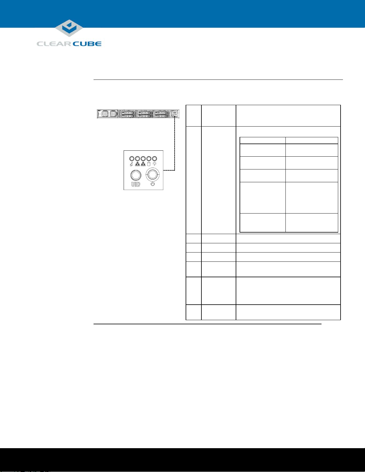
M1032W front panel
The picture and table below show indicators and buttons on the front panel of an M1032W.
Indicator
or
Button
Description
1
Information
LED
Information. Shows several states:
Status
Description
Red, continuous
Overheat condition.
Check cables.
Red, flashing
(every second)
Fan failure.
Check fan.
Red, flashing
(every 4 seconds)
Power failure. Check
power supply.
Blue, continuous
Local Unit Identifier
(UID) button has
been pressed. Use to
aid identification in
rack mount.
Blue, flashing
Remote UID is on.
Use to identify unit
from remote location.
2
NIC 2
Flashing: network activity.
3
NIC 1
Flashing: network activity.
4
HDD
Flashing: hard disk drive activity.
5
Power
(Indicator)
Continuous: power is supplied to M1032W.
6
UID
(Button)
Unit Identifier. Press to illuminate blue
LEDs on front panel and rear of chassis to
ease identification in rack mounts. LED
remains on until button is pressed again.
7
Power
(Button)
Press to power on and power off M1034W.
2 3 4
5
6
7
1
M1032W Overview and Features, Continued
Continued on next page
Page 3 of 15 P/N G0200177 Rev A, 1.0.03.03.2016
Page 4
ClearCube Technology, Inc. 3700 W Parmer Lane Austin, TX 78727 (512) 652-3500 www.clearcube.com
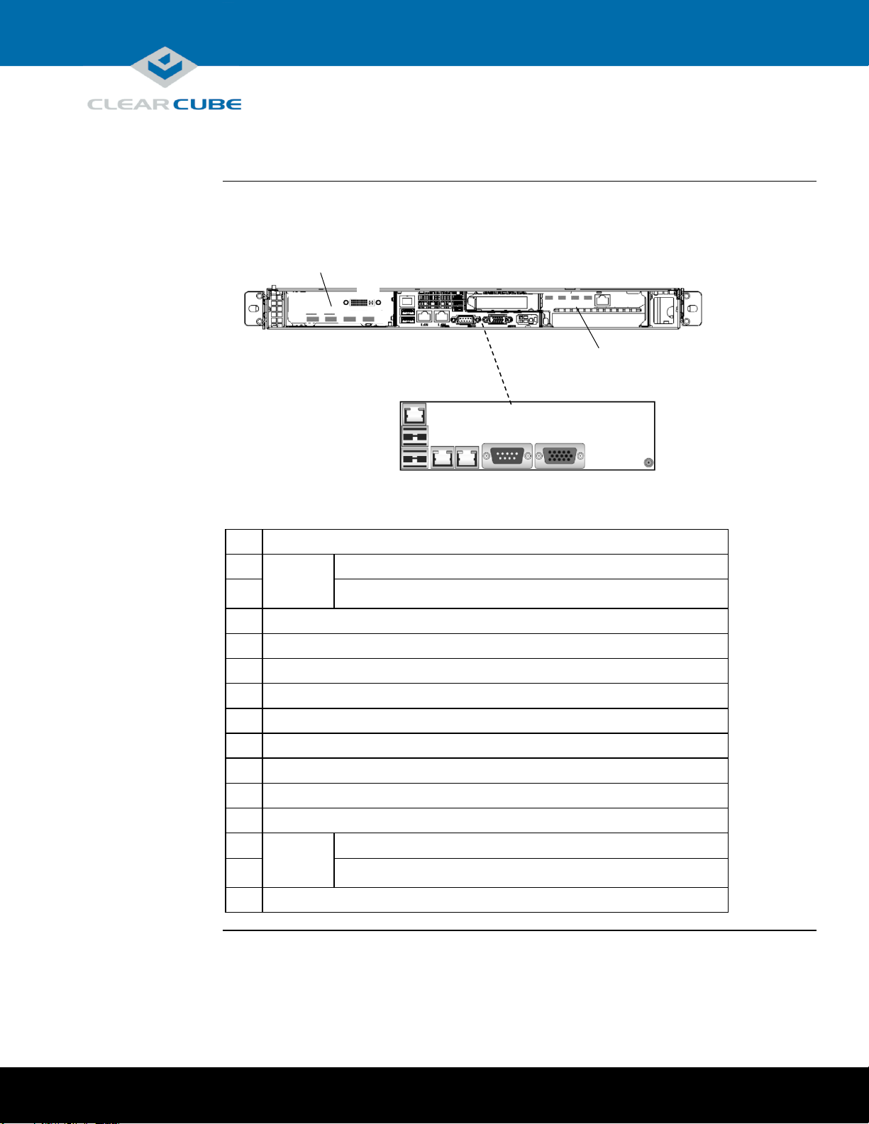
M1032W rear ports and connectors
The picture below shows ports, connectors, and buttons on the rear of an M1032W.
Description
8
GPU
Graphics
Card
DisplayPorts (number varies by configuration)
9
Dual-link DVI-I port (× 1, not on all configurations)
10
Dedicated IPMI LAN port
11
USB 3.0 port 0
12
USB 3.0 port 1
13
Ethernet LAN 1 port
14
Ethernet LAN 2 port
15
COM port
16
VGA port
17
Unit ID Button (press to illuminate LED for visual identification in rack)
18
Optional fiber NIC
19
PCoIP
Host
Card
Mini DisplayPorts (× 2 or × 4, number varies by configuration)
20
Dedicated PCoIP LAN port
21
Power connector
8
9
21
10
11
12
13
14
15
16
17
19
20
GPU Graphics Card
(Varies by Configuration)
PCoIP Host Card
(Varies by Configurations)
18
M1032W Overview and Features, Continued, Continued
Page 4 of 15 P/N G0200177 Rev A, 1.0.03.03.2016
Page 5
ClearCube Technology, Inc. 3700 W Parmer Lane Austin, TX 78727 (512) 652-3500 www.clearcube.com
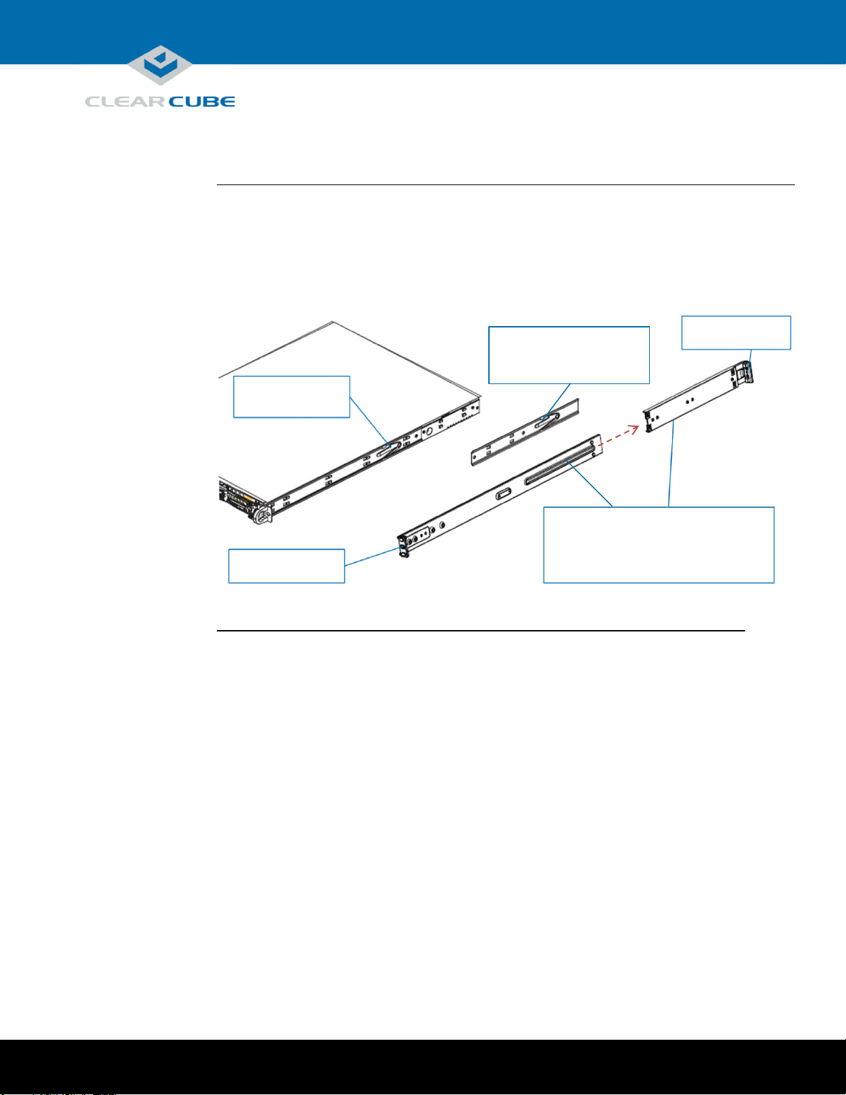
Rack rail components
Two rack rail assemblies are included with an M1032W Engineering Workstation. Each assembly has
two sections:
Inner rails: attach to the workstation chassis (the inner rail is pre-attached), and
Outer rack rails: attach to rack
The picture below shows the inner chassis rails and the outer rack rails.
Inner Rail
Pre-Assembled
Attach to Chassis
Front and Rear Brackets to Rack
Front Bracket
Rear Bracket
Rack Rails and Mounting
Inner Rail Extension
Outer Rack Rails
Slide Front into Rear and Attach
Continued on next page
Page 5 of 15 P/N G0200177 Rev A, 1.0.03.03.2016
Page 6

ClearCube Technology, Inc. 3700 W Parmer Lane Austin, TX 78727 (512) 652-3500 www.clearcube.com
Install inner rail extensions
The picture and table below show how to attach and secure the inner rail extensions.
Step
Action
1
Align the hooks on the side of the chassis with the slots on the inner rail extension.
2
Slide the extension rail toward the front of the chassis.
3
Secure the extension rail with the screws provided.
4
Repeat these steps to attach the other extension rail on the other side of the chassis.
Next step: assemble outer rack rails.
Assemble outer rack rails
Outer rack rails consist of two sections: a longer front section and a shorter rear section. Slide these together to
assemble the rail.
Step
Action
1
Identify the left and right outer rack rails by examining the ends (brackets). These brackets
bend outward as shown in “Rack rail components.”
2
Slide the front section of the outer rack rail into the rear outer rack rail as shown in “Rack rail
components.”
3
Repeat these steps to assemble the other outer rack rail.
Next step: install outer rack rails in a rack.
Step 1
Step 2
Step 3
Step 3
Rack Rails and Mounting, Continued
Continued on next page
Page 6 of 15 P/N G0200177 Rev A, 1.0.03.03.2016
Page 7

ClearCube Technology, Inc. 3700 W Parmer Lane Austin, TX 78727 (512) 652-3500 www.clearcube.com
Install outer rack rails
The picture and table below shows how to install the assembled outer rack rails in a rack.
Step
Action
1
Adjust the outer rack rails so that the outer rails
fit snugly in the rack.
2
Align the holes on the front of the outer rail with
the holes on the front of the rack and secure with
the screws provided (see A in the adjacent
picture).
3
Align the holes on the rear of the outer rack rail
with the holes on the rack and secure with the
screws provided (see B in the adjacent picture).
4
Repeat these steps with the other outer rack rail
assembly.
Next step: Install the workstation in a rack.
Installing in rack
To install an M1032W Engineering Workstation in a rack:
1. While carefully lifting the workstation, slide the inner rail extensions into the front of the outer rack rails.
2. Push the workstation into the rack until it clicks into the locked position.
Removing from rack
This picture and table below show how to remove an M1032W Engineering Workstation from a rack.
1. Press the outer rack rail latch to release the workstation chassis
(the latch is shown in the adjacent picture).
2. Carefully slide the chassis forward off of the outer rack rails and
out of the rack.
A
B
Rack Rails and Mounting, Continued
Page 7 of 15 P/N G0200177 Rev A, 1.0.03.03.2016
Page 8

ClearCube Technology, Inc. 3700 W Parmer Lane Austin, TX 78727 (512) 652-3500 www.clearcube.com
M1032W cabling
This section shows how to connect cables. Numbers in parentheses correspond to labels shown in “M1032W
front panel” and in “M1032W rear ports and connectors” to ease identification.
Step
Action
1
Install the included mounting rails to the server chassis and then install the chassis in a rack.
2
From the rear of the chassis, use the included video cables to route video from the PCoIP host
card to the GPU. Use the included DP-to-mini-DP cables.
“Cabling diagrams” below shows pictures of every GPU and PCoIP Host Card combination.
Find your configuration in the table’s Card Configuration column and connect cables as shown
in the corresponding picture.
3
Connect an Ethernet cable to the dedicated PCoIP LAN port (20) and connect the other end
to a network router or switch.
4
Optionally, connect one or more Ethernet cables to the LAN ports (13) and (14) on the rear
of the chassis and connect the other end of the cable(s) to a network router or switch.
5
If your configuration includes a fiber NIC (18), connect a fiber Ethernet cable to the Fiber
NIC (18) on the rear of the chassis and connect the other end of the cable to a network
router or switch.
6
Optionally, connect one or more Ethernet cables to the Dedicated IPMI port (10) on the
rear of the chassis and connect the other end of the cable to a network router or switch.
7
From the rear of the chassis, connect the included power cable to the power connector
(21) on the rear of the server, and connect the power cable to a power outlet.
8
From the front of the chassis, press the power button (7) to power on the server.
Setting up an M1032W Engineering Workstation
Continued on next page
Page 8 of 15 P/N G0200177 Rev A, 1.0.03.03.2016
Page 9

ClearCube Technology, Inc. 3700 W Parmer Lane Austin, TX 78727 (512) 652-3500 www.clearcube.com
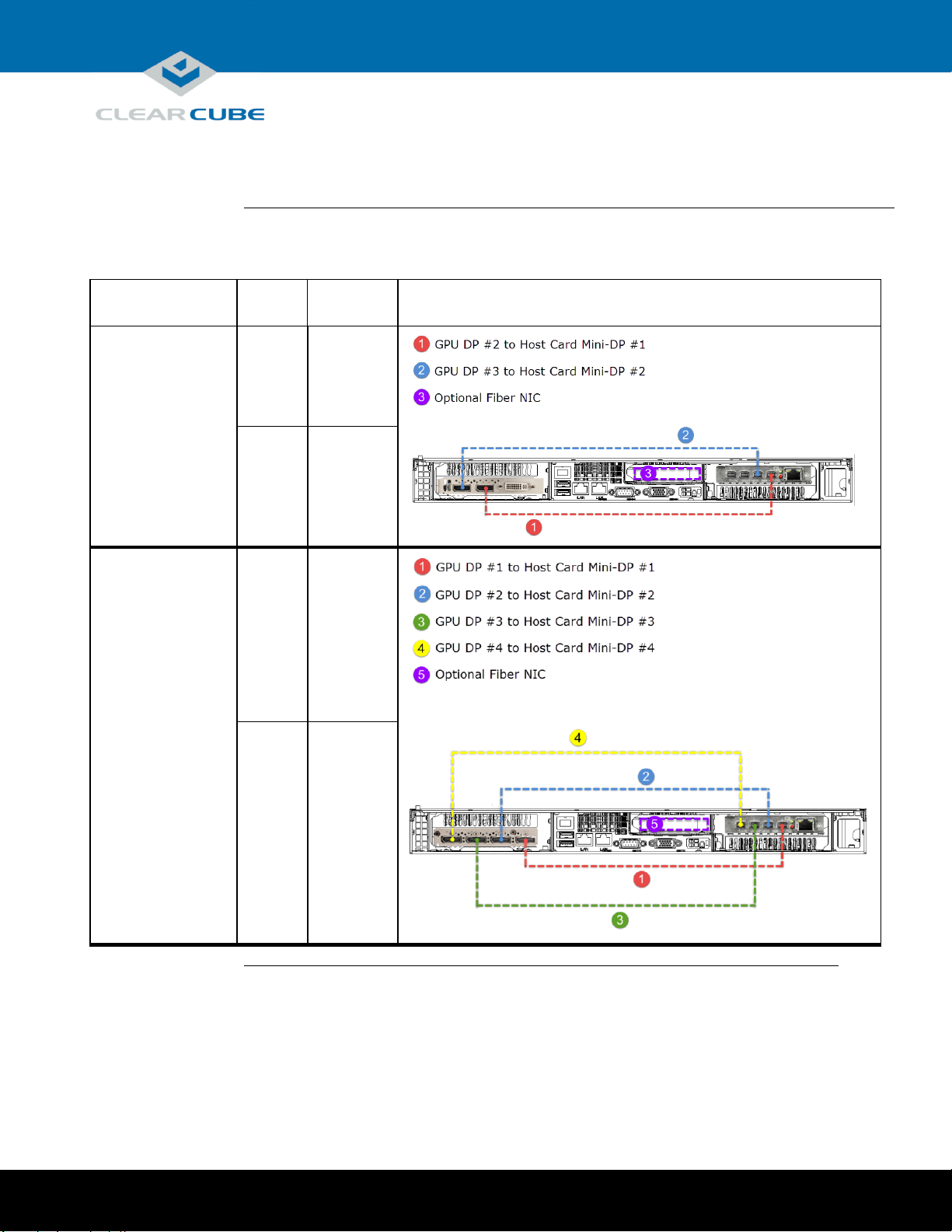
Cabling diagrams
This section shows how to connect cables between the GPU and PCoIP Host Card for each M1032W
configuration. Connect video cables on the rear of your workstation according to the configuration you ordered.
In the table below, DP indicates DisplayPort and Mini-DP indicates mini-DisplayPort.
NOTE: Host card mini-DP ports are ordered from 1 (rightmost) to 4 (leftmost). Be sure to use ports as
shown below when connecting cables from the host card to the GPU (using different ports can
cause display issues).
Card
Configuration
Displays
Resolution
Diagram
K1200 GPU and
Quad PCoIP Host Card
4
1920 × 1200
2
2560 × 1600
K2200 GPU and
Quad PCoIP Host Card
2
2560 × 1600
Setting up an M1032W Engineering Workstation, Continued
Page 9 of 15 P/N G0200177 Rev A, 1.0.03.03.2016
Continued on next page
Page 10
ClearCube Technology, Inc. 3700 W Parmer Lane Austin, TX 78727 (512) 652-3500 www.clearcube.com
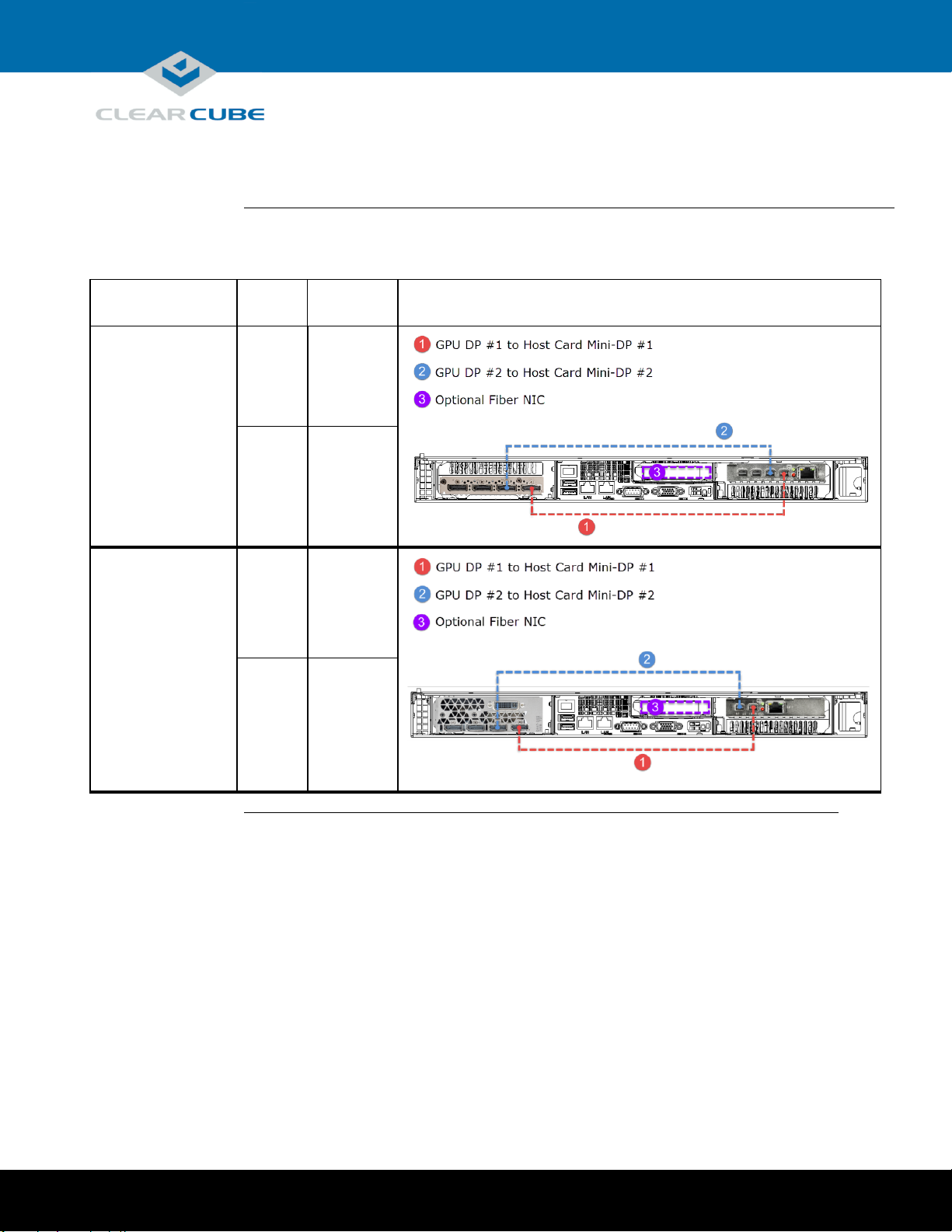
Cabling diagrams (continued)
Card
Configuration
Displays
Resolution
Diagram
K2200 GPU and
Dual PCoIP Host Card
2
1920 × 1200
1
2560 × 1600
M4000 GPU and
Quad PCoIP Host Card
4
1920 × 1200
2
2560 × 1600
Setting up an M1032W Engineering Workstation, Continued
Continued on next page
Page 10 of 15 P/N G0200177 Rev A, 1.0.03.03.2016
Page 11
ClearCube Technology, Inc. 3700 W Parmer Lane Austin, TX 78727 (512) 652-3500 www.clearcube.com
Cabling diagrams (continued)
Card
Configuration
Displays
Resolution
Diagram
M4000 GPU and
Dual PCoIP Host Card
2
1920 × 1200
1
2560 × 1600
M5000 GPU and
Dual PCoIP Host Card
2
1920 × 1200
1
2560 × 1600
Setting up an M1032W Engineering Workstation, Continued
Continued on next page
Page 11 of 15 P/N G0200177 Rev A, 1.0.03.03.2016
Page 12

ClearCube Technology, Inc. 3700 W Parmer Lane Austin, TX 78727 (512) 652-3500 www.clearcube.com
Cabling diagrams (continued)
Card
Configuration
Displays
Resolution
Diagram
M5000 GPU and
Quad PCoIP Host Card
4
1920 × 1200
2
2560 × 1600
M6000 GPU and
Dual PCoIP Host Card
2
1920 × 1200
1
2560 × 1600
Setting up an M1032W Engineering Workstation, Continued
Continued on next page
Page 12 of 15 P/N G0200177 Rev A, 1.0.03.03.2016
Page 13

ClearCube Technology, Inc. 3700 W Parmer Lane Austin, TX 78727 (512) 652-3500 www.clearcube.com
Cabling diagrams (continued)
Card
Configuration
Displays
Resolution
Diagram
M6000 GPU and
Quad PCoIP Host Card
4
1920 × 1200
2
2560 × 1600
Power option
Press the power button (7) on the front of the chassis to power on and power off a workstation. Standby power is
present when a workstation is powered off.
PCoIP host card settings
M1032W Engineering Workstations contain a PCoIP host card that requires an IP address. The IP address can be
assigned by a DHCP server or be a static IP address. Note that:
DHCP enabled is the default PCoIP host card configuration.
A fallback IP address is used when DHCP is enabled and the host card does not receive an IP address within
120 seconds.
192.168.1.101 is the host card’s Fallback IP Address.
You can access the host card’s browser-based Administrative Interface to disable DHCP mode (or to perform
other configuration and session-related actions). Enter the DHCP-assigned or the fallback IP address (shown
above) in a Web browser on the same network as the workstation.
See PC-over-IP System User’s Guide for more information about host card and zero client configuration.
Next step: You can now connect a zero client to the same network that the workstation is on and connect
the devices.
Setting up an M1032W Engineering Workstation, Continued
Page 13 of 15 P/N G0200177 Rev A, 1.0.03.03.2016
Page 14
ClearCube Technology, Inc. 3700 W Parmer Lane Austin, TX 78727 (512) 652-3500 www.clearcube.com
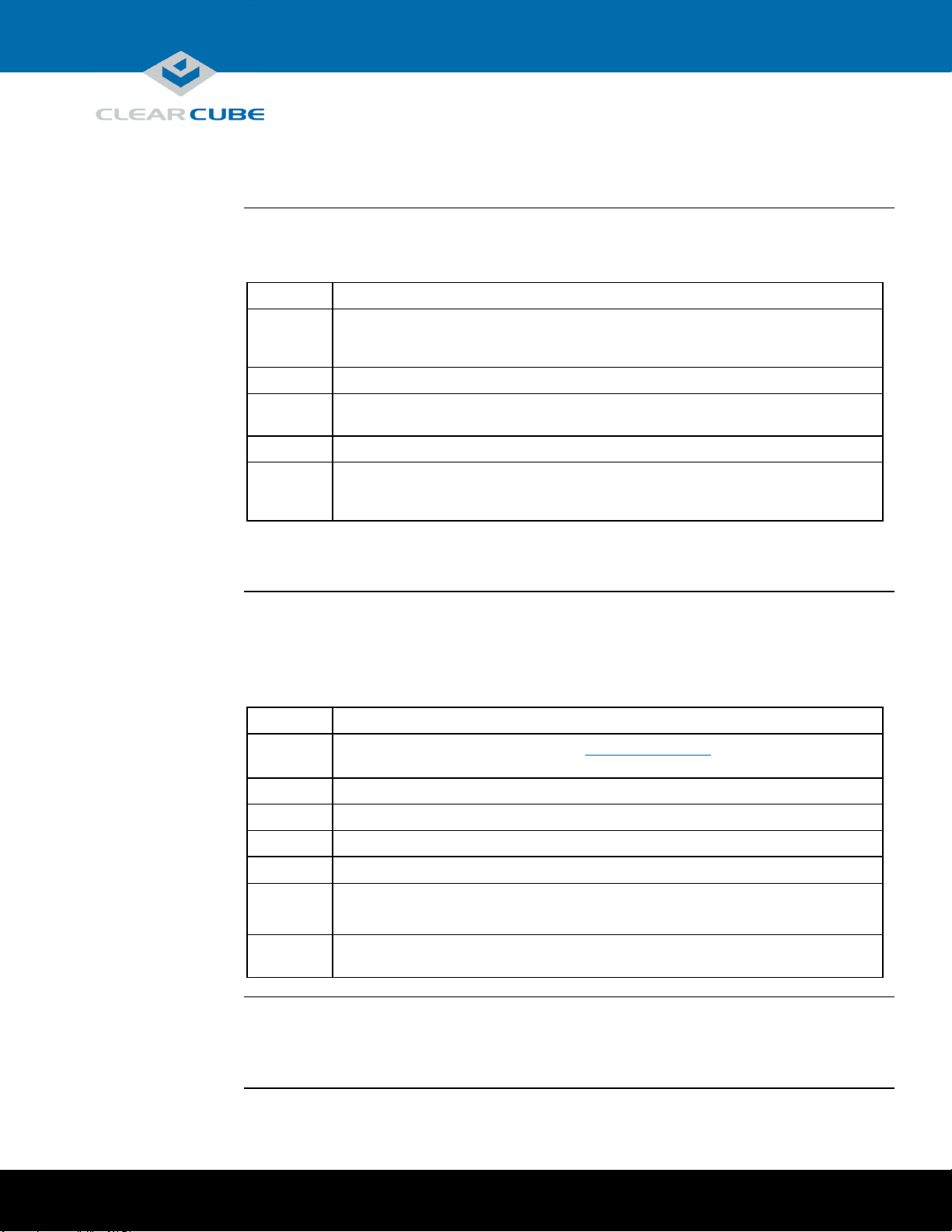
Accessing the BIOS
This section shows how to access the M1032W BIOS. It assumes the BIOS is set to the default video
configuration, which sends video to the off-board, add-on video card. Before performing these steps, note the
MAC address of the PCoIP host card in the workstation to which you are connecting.
Step
Action
1
Connect a zero client to a network switch on the same subnet as the M1032W
workstation. (See your zero client’s Quick Start Guide for more information about setting
up your zero client.)
2
Connect a keyboard to the rear of the workstation.
3
Power on the workstation. Press the DELETE key for approximate 35 seconds to enter
BIOS setup.
4
From the zero client’s on-screen display, click Connect.
5
When the zero client shows the discovered PCoIP host cards, select the MAC address of the
host card in the workstation, and then click OK. When the zero client establishes a PCoIP
session, it displays the BIOS setup screen.
The section below shows how to change the workstation’s VGA output setting so you can connect a local
VGA monitor.
Enabling VGA output
The M-Series Engineering Workstation BIOS includes two options for VGA video output: onboard (which sends
video to the onboard VGA adapter and rear VGA port) and offboard (which sends video to the add-on video card,
or GPU). The default VGA setting is offboard, which sends video to the add-on video card.
The table below shows how to change the VGA Priority setting so users can view video from a locally-connected
VGA monitor.
Step
Action
1
Begin by accessing the BIOS as shown in “Accessing the BIOS” above. After accessing the
BIOS, continue by performing the steps below.
2
From the BIOS setup screen, use the keyboard arrow keys to select the Advanced tab.
3
Select PCIe/PCI/PnP Configuration and press the ENTER key.
4
Select VGA Priority and press the ENTER key.
5
Select Onboard and press the ENTER key.
6
Press the F4 key to save your changes and exit. Select Yes and then press ENTER.
If installed, the workstation boots to the installed operating system.
7
Connect a VGA monitor to the rear of the workstation. You can now view video from the
connected VGA monitor.
More local management options
Note that for local management, you can connect a USB keyboard and mouse to the workstation, remove the
video cable connecting the PCoIP Host Card and the GPU on the rear of the workstation, and connect a monitor
directly to the GPU.
BIOS Access and VGA Output
Page 14 of 15 P/N G0200177 Rev A, 1.0.03.03.2016
Page 15
ClearCube Technology, Inc. 3700 W Parmer Lane Austin, TX 78727 (512) 652-3500 www.clearcube.com
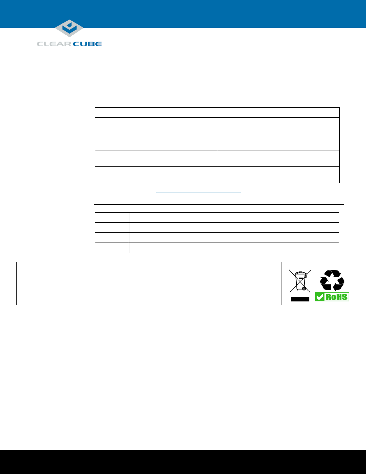
WEEE Disposal Guidelines
In the European Union, this electronic product falls under the European Directive (2002/96/EC) WEEE. When it reaches
the end of its useful life or is no longer wanted, it should not be discarded with conventional waste, but disposed of at
an approved designated recycling and/or treatment facility. Laws are different in each country, so please check with
your local authorities for proper disposal instructions. For assistance, contact ClearCube at
Related information
The table below shows additional documents about workstation configuration, operation, and maintenance.
For information about …
See …
Zero client configuration and connecting to M1032W
Engineering Workstation
Quick Start Guide included with your zero client and
PC-over-IP System User’s Guide
Creating custom operating system images
Tech Bulletin TB00265, Operating System Image
Requirements
GPU video card configuration
GPU Quick Install Guide included in the workstation
package
PCoIP device (host card and zero client)
configuration and administration
PC-over-IP System User’s Guide
Documentation is located at http://www.clearcube.com/support/.
Contacting Support
Web
UUUwww.clearcube.com/support/
Email
UUUsupport@clearcube.com
Toll-free
(866) 652-3400
Direct
(512) 652-3400
Related Information and Support
recycle@clearcube.com.
Page 15 of 15 P/N G0200177 Rev A, 1.0.03.03.2016
 Loading...