

Page 1

I/Port User’s Guide
Page 2

Technical Support
Please refer to our support website for technical updates, additional warranty
information and documentation, and software revisions:
Web: http://support.clearcube.com
Email: support@clearcube.com
Phone: (512) 652-3400 or call toll free (866) 652-3400 (United States)
ClearCube Technology Corporate Headquarters
Mailing and Shipping Address:
The ClearCube Building
8834 Capital of Texas Hwy N.
Austin, Texas 78759
Email: info@clearcube.com
Main Phone: (512) 652-3500 or call toll free (866) 652-3500 (United States)
Main Fax: (512) 652-3501
Copyrights
©2005 – 2008 by ClearCube Technology Inc. All rights reserved. Under copyright
laws, this publication may not be reproduced or transmitted in any form, electronic or
mechanical, including photocopying, recording, storing in an information retrieval
system, or translating, in whole or in part, without the prior written consent of
ClearCube Technology, Inc.
This information is subject to change without notice and ClearCube shall not be liable
for any direct, indirect, special, incidental or consequential damages in connection
with the use of this material.
Trademarks
ClearCube™, Sentral™, Blade Switching BackPack™, PC Blade™, C/Port™, and
I/Port™ are trademarks of ClearCube Technology Inc. Product and company names
mentioned herein are trademarks or trade names of their respective companies.
Patents
The ClearCube Architecture and its components described in this user manual are
protected by numerous granted and pending U.S. and international patents.
Granted patents include: US05926172, US05966056, US05994952, US06012101,
US06020839, US06037884, US06038616, US06119146, US06148182,
US06167241, US06385666, US06421393, US06426970, US06633934,
US06708247, US06735658, and US06886055.
Patents pending include: US S/N 09/755378, US S/N 10/279475, US S/N 10/19 871 9,
US S/N 10/198650, US S/N 10/409219, US S/N 09/728667, US S/N 09/728669, US
S/N 10/411804, US S/N 10/411908, US S/N 10/458853, US S/N 10/364584, US S/N
10/301536, US S/N 60/411066, US S/N 10/662933, US S/N 10/662889, US S/N
10/662932, US S/N 10/662968, US S/N 10/301563, US S/N 10/662936, US S/N
10/301518, US S/N 10/662955 and US S/N 10/662954.
Inquiries regarding patented technology should be directed to ClearCube Corporate
Headquarters.
Page 3

Contents
How to Use This Guide . . . . . . . . . . . . . . . . . . . . . . . . . . . . . . . . . . . . . . . . . . . . . . . . . . . . . . . . . . . . v
FCC Warning . . . . . . . . . . . . . . . . . . . . . . . . . . . . . . . . . . . . . . . . . . . . . . . . . . . . . . . . . . . . . . . . . . . . v
California Proposition 65 Statement . . . . . . . . . . . . . . . . . . . . . . . . . . . . . . . . . . . . . . . . . . . . . . . . . . v
WEEE Information . . . . . . . . . . . . . . . . . . . . . . . . . . . . . . . . . . . . . . . . . . . . . . . . . . . . . . . . . . . . . . vi
Warning Regarding Medical and Clinical Use of ClearCube Products . . . . . . . . . . . . . . . . . . . . . . . vi
Symbols . . . . . . . . . . . . . . . . . . . . . . . . . . . . . . . . . . . . . . . . . . . . . . . . . . . . . . . . . . . . . . . . . . . . . . . vii
Safety Guidelines . . . . . . . . . . . . . . . . . . . . . . . . . . . . . . . . . . . . . . . . . . . . . . . . . . . . . . . . . . . . . . . viii
Chapter 1. ClearCube I/Port Overview . . . . . . . . . . . . . . . . . . . . . . . . . . . . . . . . . . . . . . . . . . . . 1
Thin Clients and Operating Systems . . . . . . . . . . . . . . . . . . . . . . . . . . . . . . . . . . . . . . . . . . . . . . . . . . 2
I8820 . . . . . . . . . . . . . . . . . . . . . . . . . . . . . . . . . . . . . . . . . . . . . . . . . . . . . . . . . . . . . . . . . . . . . . . . . . 3
I8020 . . . . . . . . . . . . . . . . . . . . . . . . . . . . . . . . . . . . . . . . . . . . . . . . . . . . . . . . . . . . . . . . . . . . . . . . . . 3
I8330 . . . . . . . . . . . . . . . . . . . . . . . . . . . . . . . . . . . . . . . . . . . . . . . . . . . . . . . . . . . . . . . . . . . . . . . . . . 3
I9420 and I9440 . . . . . . . . . . . . . . . . . . . . . . . . . . . . . . . . . . . . . . . . . . . . . . . . . . . . . . . . . . . . . . . . . . 3
Supporting Technology and Software . . . . . . . . . . . . . . . . . . . . . . . . . . . . . . . . . . . . . . . . . . . . . . . . . 4
Remote Desktop Protocol . . . . . . . . . . . . . . . . . . . . . . . . . . . . . . . . . . . . . . . . . . . . . . . . . . . . . . . 4
ClearCube Sentral . . . . . . . . . . . . . . . . . . . . . . . . . . . . . . . . . . . . . . . . . . . . . . . . . . . . . . . . . . . . . 5
Neoware ezRemote Manager Software . . . . . . . . . . . . . . . . . . . . . . . . . . . . . . . . . . . . . . . . . . . . . 5
I83xx Driver and Admin Utility . . . . . . . . . . . . . . . . . . . . . . . . . . . . . . . . . . . . . . . . . . . . . . . . . . 5
PCoIP . . . . . . . . . . . . . . . . . . . . . . . . . . . . . . . . . . . . . . . . . . . . . . . . . . . . . . . . . . . . . . . . . . . . . . . 6
Chapter 2. I/Port Installation . . . . . . . . . . . . . . . . . . . . . . . . . . . . . . . . . . . . . . . . . . . . . . . . . . . . 7
Caution Statements . . . . . . . . . . . . . . . . . . . . . . . . . . . . . . . . . . . . . . . . . . . . . . . . . . . . . . . . . . . . . . . 7
Setup . . . . . . . . . . . . . . . . . . . . . . . . . . . . . . . . . . . . . . . . . . . . . . . . . . . . . . . . . . . . . . . . . . . . . . . 7
Orientation and Venting . . . . . . . . . . . . . . . . . . . . . . . . . . . . . . . . . . . . . . . . . . . . . . . . . . . . . . . . . 7
Power Sources . . . . . . . . . . . . . . . . . . . . . . . . . . . . . . . . . . . . . . . . . . . . . . . . . . . . . . . . . . . . . . . . 8
Cable Requirements . . . . . . . . . . . . . . . . . . . . . . . . . . . . . . . . . . . . . . . . . . . . . . . . . . . . . . . . . . . . . . . 8
Unpacking the I/Port . . . . . . . . . . . . . . . . . . . . . . . . . . . . . . . . . . . . . . . . . . . . . . . . . . . . . . . . . . . . . . 9
Setting up the I/Port . . . . . . . . . . . . . . . . . . . . . . . . . . . . . . . . . . . . . . . . . . . . . . . . . . . . . . . . . . . . . . . 9
Using the I94xx Mounting Bracket . . . . . . . . . . . . . . . . . . . . . . . . . . . . . . . . . . . . . . . . . . . . . . . . . . 12
Configuring the Sentral Console for the I/Port Connection . . . . . . . . . . . . . . . . . . . . . . . . . . . . . . . 12
Enabling RDP on Hosts for I/Port Connections . . . . . . . . . . . . . . . . . . . . . . . . . . . . . . . . . . . . . . . . 13
Configuring the XPe I/Port . . . . . . . . . . . . . . . . . . . . . . . . . . . . . . . . . . . . . . . . . . . . . . . . . . . . . . . . 13
iii
Page 4

Optimizing RDP and the I/Port . . . . . . . . . . . . . . . . . . . . . . . . . . . . . . . . . . . . . . . . . . . . . . . . . . 14
Adding a Printer . . . . . . . . . . . . . . . . . . . . . . . . . . . . . . . . . . . . . . . . . . . . . . . . . . . . . . . . . . . . . . 17
Configuring NeoLinux I/Ports . . . . . . . . . . . . . . . . . . . . . . . . . . . . . . . . . . . . . . . . . . . . . . . . . . . . . . 18
Configuring the I8330 I/Port . . . . . . . . . . . . . . . . . . . . . . . . . . . . . . . . . . . . . . . . . . . . . . . . . . . . . . . 19
Sentral Configuration . . . . . . . . . . . . . . . . . . . . . . . . . . . . . . . . . . . . . . . . . . . . . . . . . . . . . . . . . . 19
Direct Connection . . . . . . . . . . . . . . . . . . . . . . . . . . . . . . . . . . . . . . . . . . . . . . . . . . . . . . . . . . . . 20
Operating Notes . . . . . . . . . . . . . . . . . . . . . . . . . . . . . . . . . . . . . . . . . . . . . . . . . . . . . . . . . . . . . . 20
Configuring the I9420 I/Port . . . . . . . . . . . . . . . . . . . . . . . . . . . . . . . . . . . . . . . . . . . . . . . . . . . . . . . 22
Setting up Connections . . . . . . . . . . . . . . . . . . . . . . . . . . . . . . . . . . . . . . . . . . . . . . . . . . . . . . . . 23
Direct Connection . . . . . . . . . . . . . . . . . . . . . . . . . . . . . . . . . . . . . . . . . . . . . . . . . . . . . . . . . 23
DHCP Connection . . . . . . . . . . . . . . . . . . . . . . . . . . . . . . . . . . . . . . . . . . . . . . . . . . . . . . . . . 24
Sentral Connection . . . . . . . . . . . . . . . . . . . . . . . . . . . . . . . . . . . . . . . . . . . . . . . . . . . . . . . . . 25
I9420 I/Port Display Resolution and Bandwidth Requirements . . . . . . . . . . . . . . . . . . . . . . . . . 26
Deploying I9440 I/Ports . . . . . . . . . . . . . . . . . . . . . . . . . . . . . . . . . . . . . . . . . . . . . . . . . . . . . . . . . . . 26
Updating I/Port Software . . . . . . . . . . . . . . . . . . . . . . . . . . . . . . . . . . . . . . . . . . . . . . . . . . . . . . . . . . 27
Best Practices for I/Ports . . . . . . . . . . . . . . . . . . . . . . . . . . . . . . . . . . . . . . . . . . . . . . . . . . . . . . . . . . 27
RDP-Based I/Ports . . . . . . . . . . . . . . . . . . . . . . . . . . . . . . . . . . . . . . . . . . . . . . . . . . . . . . . . . . . . 27
I8330 I/Ports . . . . . . . . . . . . . . . . . . . . . . . . . . . . . . . . . . . . . . . . . . . . . . . . . . . . . . . . . . . . . . . . 29
I94xx I/Ports . . . . . . . . . . . . . . . . . . . . . . . . . . . . . . . . . . . . . . . . . . . . . . . . . . . . . . . . . . . . . . . . 30
Appendix A. Specifications . . . . . . . . . . . . . . . . . . . . . . . . . . . . . . . . . . . . . . . . . . . . . . . . . . . . 31
Appendix B. Troubleshooting . . . . . . . . . . . . . . . . . . . . . . . . . . . . . . . . . . . . . . . . . . . . . . . . . . 35
Appendix C. Technical Support . . . . . . . . . . . . . . . . . . . . . . . . . . . . . . . . . . . . . . . . . . . . . . . . . 39
iv
Page 5
How to Use This Guide
This manual provides all the product and installation information needed to set up and run
ClearCube Technology’s I/Port architecture for managed desktop environments. Familiarize
yourself with the ClearCube architecture and product descriptions and read through the entire
installation and setup procedures before beginning installation.
If you encounter any problems, contact Technical Support using the contact information
provided on the inside front cover of this manual.
FCC Warning
This equipment generates and uses radio frequency energy and, if not installed and used in
strict accordance with the instructions in this manual, may cause interference to radio and
television reception. Changes or modifications not expressly approved by ClearCube
Technology could void the user's authority to operate the equipment under the FCC Rules.
California Proposition 65 Statement
WARNING: ClearCube products contain chemicals, including lead,
known to the State of California to cause cancer, birth defects, or other
reproductive harm. Wash hands after handling.
ClearCube products should be disposed of in accordance with local laws governing computer
equipment disposal.
•v
Page 6
WEEE Information
The products described in this document are subject to regulation under the European Union
Directive 2002/96/EC, that mandates separate waste collection, treatment, and recycling of
electronic products. This directive is commonly known as WEEE, for Waste from Electrical
and Electronic Equipment, and its intent is to promote the safe and sensible disposal of
products that have outlived their usefulness
The “crossed-out” trash bin symbol, shown to the left, identifies products that should be
recycled, not simply discarded. ClearCube Technology supports the reuse, recycling,
recovery, and responsible disposal of all products, not just our systems.
ClearCube Technology is committed to meeting the requirements of the European Union
WEEE Directive and is currently developing country-specific implementation plans that
comply with the WEEE legislation. The goal of the directive is to reduce the environmental
impact due to the disposal of electrical and electronic equipment that has reached the end of its
useful service life. This directive goes into enforcement on August 13, 2005.
ClearCube products are sold exclusively to commercial and industrial customers and not to
private households. Under the WEEE legislation terms, commercial and industrial customers
have the responsibility to ensure that all electrical and electronic equipment is disposed of
properly and in accordance with all applicable laws and local regulations. For more
information, visit the ClearCube Technology web site at www.clearcube.com
recycle@clearcube.com
, email at
, or call at (866) 652-3400 or +1 (512) 652-3400.
Materials used in this product, if not disposed of properly, could have adverse effects on the
environment and human health. Do not dispose of these products in unsorted municipal waste
containers. Deliver electronic waste only to an approved recycling, and/or treatment facility. If
one is not available, contact ClearCube for assistance.
Warning Regarding Medical and Clinical Use of
ClearCube Products
ClearCube products are not designed with components and testing for a level of reliability
suitable for use in or in connection with surgical implants or as critical components in any life
support systems whose failure to perform can reasonably be expected to cause significant
injury to a human. Applications of ClearCube products involving medical or clinical treatment
can create a potential for death or bodily injury caused by product failure, or by errors on the
part of the user. Because each end-user system environment is customized and differs from
ClearCube testing platforms and because a user may use ClearCube products in combination
with other products in a manner not evaluated or contemplated by ClearCube, the user is
ultimately responsible for verifying and validating the suitability of ClearCube products
whenever ClearCube products are incorporated in a system, including, without limitation, the
appropriate design, process and safety level of such system or application.
vi •
Page 7
Symbols
Symbols are used on the equipment to convey specific information to the operator and service
person. It is important to understand the intended meaning of these symbols. Below are the
graphical symbols that are used on ClearCube Technology, Inc. Products and their meaning.
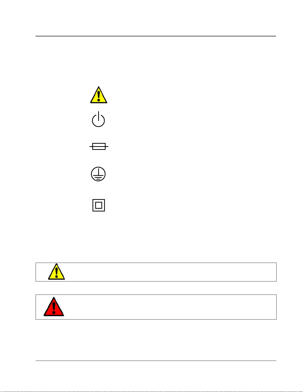
Refer to Manual
Used on the equipment’s rating label to direct the operator or service person
to the manual for additional information.
Power
Identifies the soft-start switch located on rear of the host or blade, used to
power the host on and off.
Fuse
Located on equipment rating label. Symbol is accompanied with the specifications needed for replacement. Only qualified technicians should perform
this operation.
Protective Earth Terminal
Identifies the terminal that is used to connect all metal parts of the enclosure
through an external conductor to ground for the protection against electrical
shock in a fault condition.
Equipment Protection Class II
May be located on the power adapter’s rating label. Indicates that equipment
is double insulated from hazardous voltages. Not to be confused with “Class
2” that is a US National Electrical Code (NEC) circuit classification.
These same symbols are used within this document where appropriate to indicate situations
that merit checking this or another manual, or situations that could result in damage to
equipment or physical injury.
CAUTION: A Caution notice in this manual indicates that equipment damage
or minor injury may result if proper procedures are not followed.
WARNING – A Warning notice in this manual indicates that
catastrophic equipment damage, or serious injury including
death may result if proper procedures are not followed.
•vii
Page 8

Safety Guidelines
Before undertaking any troubleshooting or maintenance procedure, read carefully all
WARNING and CAUTION notices. This equipment contains voltage hazardous to
human life and is capable of inflicting personal injury.
• Installations – ClearCube equipment is required to be installed in accordance with the
local electrical codes and may be subject to inspection by the authority having jurisdiction.
• Chassis Grounding – ClearCube’s chassis and Fiber Transceiver has been designed with
a three-conductor IEC 60320 appliance inlet that – with the proper power cord – connects
the building’s external protective earthing conductor to all accessible metal parts of the
enclosure. To minimize shock hazard, make sure your electrical power outlet has an
appropriate earth safety ground that is connected each time you power on the equipment.
Swedish safety regulations require the following statement:
—Apparaten skall anslutas till jordat uttag när den anslutas till ett nätuerk.—
Finnish safety regulations require the following statement:
— Laite on liitettävä suojamaadoituskoskettimilla varustettuun pistorasiaan.—
• Power Cord Selection – ClearCube or ClearCube’s Distributors provides power cords
that are specifically designed for use with that particular piece of equipment and are
approved for use by the local authority having jurisdiction in the country where the
equipment is put into service. Please refer to the installation sections of this manual for
specific power cord requirements. For replacement of power cords, refer to Appendix C –
Technical Support.
• Power Adapters – ClearCube or ClearCube’s Distributors provides power adapters that
are specifically designed for use with that particular piece of equipment and are approved
for use by the local authority having jurisdiction in the country where the equipment is put
into service. Please refer to the installation sections of this manual for specific power cord
requirements. For replacement of power cords, refer to Appendix C – Technical Support.
• IT Power Systems – ClearCube equipment has been evaluated and found to be
compatible with IT power distribution systems with a phase-to-phase voltage not to
exceed 240 V.
• Live Circuits – Operating personnel and service personnel must not remove protective
covers when operating the ClearCube chassis. Adjustments and service to internal
components must be undertaken by qualified service technicians. During any service of
this product other than replacing a host, PC blade, or the fan tray, the main connector to
the premise wiring must be disconnected. Dangerous voltages may be present under
certain conditions. Use extreme caution.
• Explosive Atmosphere – Do not operate the chassis in conditions where flammable gases
are present. Under such conditions this equipment is unsafe and may ignite the gases or
gas fumes.
• Part Replacement – Only service equipment with parts that are exact replacements, both
electrically and mechanically. Contact ClearCube Technology for replacement part
information. Installation of parts that are not direct replacements will void the warranty
and may cause harm to personnel operating the chassis. Furthermore, damage or fire may
occur if replacement parts are unsuitable.
viii •
Page 9

• Modification – Do not modify any part of the I/Port, chassis, host, or PC blade from its
original condition. Modifications may result in hazards.
CAUTION: Use of controls or adjustments or performance of procedures
other than those specified herein may result in hazardous radia tion
exposure.
•ix
Page 10

x•
Page 11

Chapter 1. ClearCube I/Port Overview
The ClearCube architecture delivers PC functionality to the desktop from a secure, centralized
location. This results in dramatic increases in manageability and security while providing
mission-critical reliability, performance, and uptime improvements with lowered costs.
Replacing a traditional PC box with a ClearCube C/Port or I/Port in an office or cubicle also
saves space, eliminates fan noise and simplifies cabling resulting in a clear cube. The key
components of the ClearCube Architecture are:
• Host or Blade – a remotely-located computer in a dense form factor.
• Chassis – a centralized host or blade housing that provides the power for each host and
accepts a wide variety of chassis modules.
• Chassis Module – a modular interface card that plugs into a chassis and provides
thin client, management, and network connections.
• Thin Client – a remote desktop unit (C/Port or I/Port) to which standard peripherals are
connected.
• System Management – Sentral™ system management software and monitoring hardware
that is built into ClearCube blades, ClearCube chassis, and ClearCube I/Ports.
The ClearCube I/Port is a thin client that connects to hosts over a standard Ethernet network.
The I/Port delivers video and peripheral signals to a local user from a centralized host using
Ethernet protocol, allowing it to work over standard switched networks. Unlike ClearCube
C/Ports, I/Ports do not require point-to-point connections to hosts (homerun cabling is not
required).
The I/Port enables IT managers use existing IP networks and cabling infrastructure, regardless
of the distance between users' desktops and their centralized hosts.
This guide describes the following I/Ports:
• I8020 – NeoLinux
• I8820 – Windows
• I8330 – OS-independent
• I9420 – OS-independent
• I9440 – OS-independent
Figure 1
connections between I/Ports and host or blades installed in the data center.
on page 2 shows the ClearCube family of I/Ports. Figure 3on page 8 shows the
®
operating system
®
XPe operating system
•1
Page 12
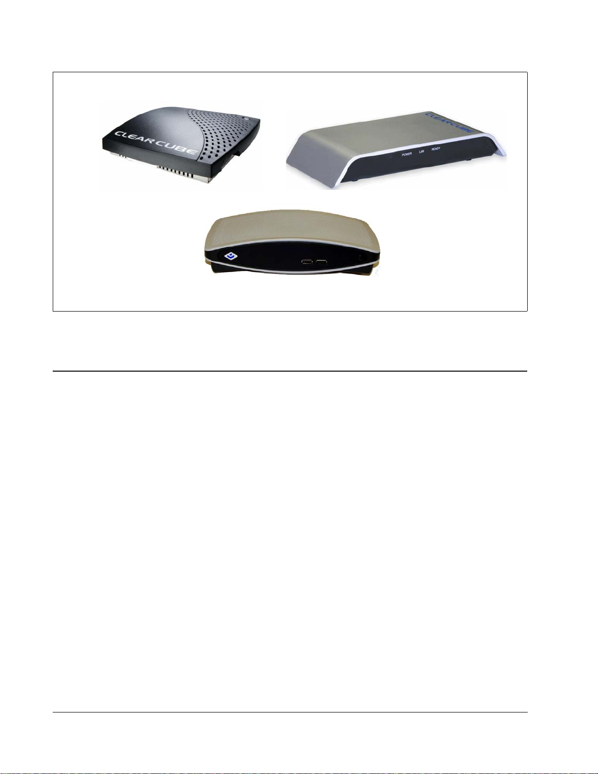
I8020 / I8820
I9420 and I9440
Figure 1. ClearCube I/Ports
Thin Clients and Operating Systems
ClearCube I/Ports are available with:
• Windows XPe operating system—Windows XPe offers the power of Windows XP in a
compact, componentized form.
• Neoware NeoLinux operating system—NeoLinux is a tailored version of Linux
targeted at and optimized for a broad range of information appliances and thin clients.
NeoLinux features a secure, read-only file system that enabling applications run on the
host, not on the local thin client. Neoware employs a hardened default security profile and
a streamlined user security environment.
I8330
®
that is
2•
Both operating systems have the advantage of being remotely manageable using
ClearCube Sentral and Neoware ezRemote Manager software.
• PCoIP™ processors—Enable thin clients to deliver a high-end PC experience to multiple
monitors over a standard network, without an operating system. PCoIP also transparently
redirects USB from the thin client to the host, or computing device. ClearCube I9xx
I/Ports use PCoIP processors.
Page 13

I8820
I8020
The I8820 features Windows XPe as the operating system. The small form factor of the I8820
I/Port allows customers to easily mount the I8820 under desks, vertically on walls, or behind a
monitor using the optional mounting bracket.
Connecting to hosts using RDP, the I8820 I/Port delivers video and peripheral signals to users
using Ethernet, eliminating distance limitations between hosts and users. The I8820 supports
ClearCube Sentral, which sets up and dynamically allocate the RDP connections between the
I/Ports and hosts. Additionally, Sentral provides sparing and dynamic allocation capabilities
for ClearCube I/Ports.
The I8020 runs an embedded Linux operating system called NeoLinux. The I8020 features the
same form factor as the I8820, allowing the same flexibility in mounting at the user’s work
space.
Like the I8820, the I8020 eliminates any distance limitations between the host and the user by
using RDP. Hosts running Windows XP can work with the NeoLinux-based I8020 without
requiring any upgrades. The I8020 also supports Sentral.
I8330
The I8330 connects over Ethernet and does not use RDP as the extension prot ocol. Because
this technology eliminates the need for an operating system on the desktop device, I8330
I/Ports significantly reduce the likelihood of viruses on thin clients.
I9420 and I9440
The I9420 I/Port and the I9440 I/Port use PCoIP processors to deliver simultaneous full
screen, full motion video at high resolutions on the following numbers of monitors:
• I9420—One or two monitors when connected to hosts containing V5120 Dual Host video cards
• I9440—One to four monitors when connected to hosts containing V5140 Quad Host video cards
You can specify a different resolution and display orientation (portrait or landscape) for each
monitor connected to an I94xx I/Port.
You can deploy I9420 and I9440 I/Ports on:
•3
Page 14

• Existing Ethernet networks
• Secure point-to-point connections to prevent desktop-display data commingling with other
network traffic
I94xx I/Ports do not require unique OS drivers, and support the following standard
peripherals:
• Multiple monitors
• Keyboards
• Mouse devices
• Audio devices
• USB peripherals, including isochronous USB devices
Supporting Technology and Software
The following applications work together to enable and enhance I/Port functionality:
• Remote Desktop Protocol (RDP)
• ClearCube Sentral
•Neoware ezRemote Manager
• I83xx Driver and Admin Utility
• PC-over-IP™ (PCoIP) technology
Remote Desktop Protocol
Microsoft Remote Desktop Protocol (RDP) is a presentation protocol that allows the I/Port to
communicate with a host. RDP works across any TCP/IP connection, such as a local area
network (LAN), wide area network (WAN), or virtual private network (VPN) connection.
RDP is the delivery mechanism for video, mouse, keyboard, and USB communications
between the I/Port and the host.
When using Remote Desktop Protocol from the I/Port, many of the local I/Port resources are
available within the session, for example:
• Peripheral Redirection – Peripherals connected to a local I/Port appear as if they are
connected to a user's host. RDP supports redirection for devices such as:
– Human Interface Devices (such as keyboards and pointing devices)
– TWAIN devices (such as scanners)
– Local drives (such as mass storage devices)
–Printers
4•
– Devices attached the I/Port’s local serial port and parallel port
Page 15

• Audio – The audio streams, such as .wav and .mp3 files, play through the I/Port’s
speaker connection. RDP provides downstream audio only. RDP only supports audio out
(i.e., from the host to the I/Port) so speakers connected to an I/Port can play sound
generated by the host. However, audio in (i.e., from the I/Port to the host) isn't supported
by RDP so audio devices such as microphones cannot transmit back to the host.
ClearCube Sentral
ClearCube Sentral provides IT administrators with a comprehensive set of features and
functionality for managing their I/Port environments. Sentral can optimize hardware
utilization by dynamically allocating I/Ports to a defined pool of hosts.
Sentral tracks host loading statistics and automatically initiates a connection to the least
utilized host when each user logs on. Power users can be mapped to an individual host
ensuring maximum performance. Auto discovery of I/Ports and hosts makes it easy to
inventory and manage assets. In addition, an update feature makes it easy to update the Sentral
Client on each I/Port when new software versions are made available. Finally, Sentral delivers
server-level availability to end users by enabling Administrators to easily switch an I/Port user
to a spare host should they experience a problem.
Neoware ezRemote Manager Software
Neoware ezRemote Manager is a remote management tool for keeping I/Ports up-to-date and
is used as a companion to Sentral. ezRemote Manager is based on a straightforward,
easy-to-use interface that allows administrators to remotely push drivers, applications, and
security updates via snap-ins, to a single I/Port or an entire enterprise. Snap-ins are
deployment packages that can automatically install peripheral drivers or local applications
such as VPN clients. ezRM can fully re-image a device in order to deploy a customized image
enterprise-wide or for disaster recovery on individual devices. ezRM is also the tool for
keeping XPe based units up-to-date with Microsoft security updates.
I83xx Driver and Admin Utility
The I83xx driver and the I83xx admin utility enable support for I83xx–series I/Ports in a
Sentral environment and are available on the Sentral installation CD.
Note: The I83xx driver and the I83xx admin utility are required only if you use I83xx I/Ports in
Each blade or virtual machine to which an I8330 connects must have the I83xx driver
installed. See Sentral Administrator’s Guide for more information about the I83xx driver and
the I83xx admin utility.
your environment. Ensure that you do not install I83xx drivers or admin utility on hosts
connected to I94xx I/Ports.
•5
Page 16
PCoIP
I9420 and I9440 I/Ports use PCoIP technology to deliver high–performance video and audio to
users. PCoIP technology consists of dedicated processors on the thin client (I94xx I/Port) and
on the host to which the thin client connects. ClearCube hosts can support I94xx I/Ports by
using one of the following host–side cards:
• V5120 Dual Host card—Contained in specific A–series and R–series PC blades to
support I9420 I/Ports
• V5140 Quad Host card—Contained in specific A–series PC blades to support I9440
I/Ports
Network Switch
DHCP
I94xx I/Port
Figure 2. Typical I94xx architecture
Chassis and Blades
6•
Page 17

Chapter 2. I/Port Installation
Caution Statements
Improper connection, mounting, or use of this product could result in component failure or
undesired interference. Read the following caution statements before setting up and operating
your I/Port.
Setup
• Do not connect to AC power until all other connections are made, including the power
adapter. Connecting or disconnecting components or equipment on the back panel when
the I/Port is receiving AC power can cause power surges and damage the device.
• Do not force a connector into its socket. If any undue resistance is encountered, ensure that
the connector is correctly oriented to the receptacle.
• Do not attach the I/Port to a telephone jack or other powered network connection. This
will permanently damage the I/Port. This damage is not covered under the ClearCube
Technology limited warranty.
Orientation and Venting
• Allow sufficient space around the I/Port for ventilation. Do not place the device in any
enclosure that restricts airflow around the device. Do not place any objects on the device.
Product environmental specifications are listed in Appendix A. Specifications
• The I8020 and I8820 can be mounted horizontally or vertically. An optional mounting
bracket is available from ClearCube. Provide adequate clearanc e around the I/Port for
cooling.
• The I8330 can be mounted horizontally or vertically. Provide adequate clea rance around
the I/Port for cooling.
• Mount I9420 I/Ports and I9440 I/Ports flat (that is, horizontally). A mounting bracket is
included with each I9420 and I9440. See "Using the I94xx Mounting Bracket
for instructions about how to mount the bracket and for information about the minimum
clearance specifications.
on page 31.
" on page 12
•7
Page 18

Power Sources
• To e nsure regulatory compliance, use only the power supply included in the shipping
carton with the I/Port, or a ClearCube-approved equivalent.
• Surge protectors for electrical devices are recommended in areas of frequent lightning.
However, when lightning is occurring, your equipment should be properly shut down and
unplugged from AC power until the storm has passed.
• Be careful to not interrupt power while the I/Port is receiving a software update.
Cable Requirements
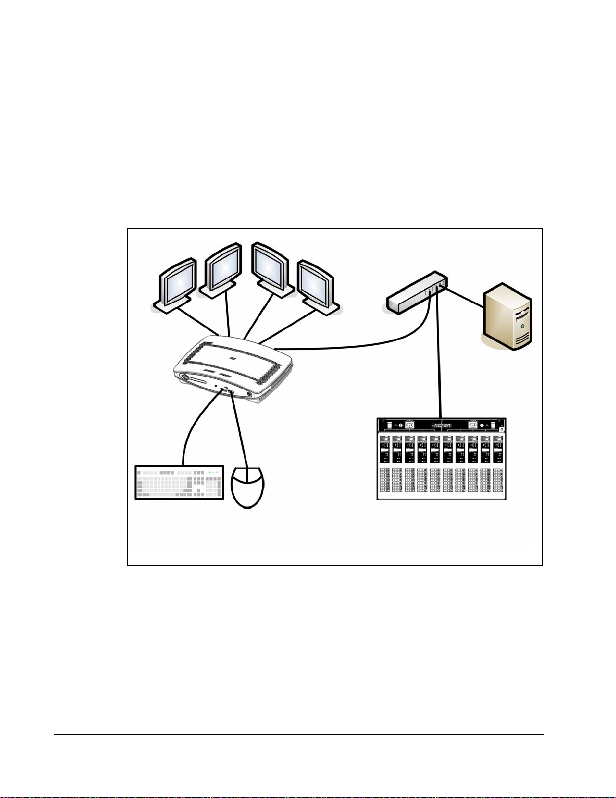
For I/Port installations, you need 16 CAT5 cables per chassis to connect the hosts to your
network switch. You will not need to connect any cables to the C/Port connections. With
I/Ports, the cables going to the desktop are connected directly to your network switch. Figure 3
on this page provides schematics of the cabling required to connect your R–Series chassis to
I/Ports and your Ethernet network.
with I/Ports
Data CenterUser Desktops
Chassis
Admin C/Port
and Terminal
Network
Switch
Figure 3. R–Series Chassis Cabling Diagram
Ethernet
Cables
8•
Page 19

The following figure shows a typical cabling configuration to connect I9420 I/Ports and I9440
I/Ports to an A3100 chassis.
A3100 Chassis with 10 A1410 Blades
. . . .
PCoIP
PCoIP
. . . .
PRI
SEC
BLADE 5
Network Switch
Thin Clients and Peripherals
Figure 4. A3100 Chassis Cabling Diagram
PRI
BLADE 6
SEC
External Data Sources
and Entities
Data
Unpacking the I/Port
When unpacking the I/Port, you will find one of each of the following items:
• I/Port unit
• I/Port power supply and power cord (optional for some regions)
• Optional mouse and keyboard (may be shipped separately)
• Mounting bracket and mounting screws are included with I9420
Setting up the I/Port
To set up your I/Port, do the following:
1. Place the I/Port on a desktop or other solid surface.
2. Make connections as appropriate for your I/Port, as shown in one of the following figures:
•9
Page 20

– I8020 or I8820 I/Port—Figure 5 on this page
– I8330 I/Port—Figure 6
– I9420 I/Port—Figure 7
on this page
on page 11
– I9440 I/Port—Figure 8 on page 11
Do not attach the I/Port to a telephone jack. This will permanently damage
the I/Port. This damage is not covered under the ClearCube Technology
limited warranty.
11
10
1 2 3 4 5 6 7 8 9
1.
Power supply connector
2. VGA video port 6. USB 1.1 port (rear panel) 10. USB 1.1 ports (front panel)
3. PS/2 mouse port
4. PS/2 keyboard port 8. Audio line out
5. Serial port 9. Audio line in (local use only)
7.
10/100 BaseT Ethernet port
11. On/Off switch
Figure 5. I8020 and I8820 I/Port Connections
1
1.
USB 1.1 ports (four)
2. 10/100 BaseT Ethernet port 6. Microphone in 10. Kensington lock slot
3. PS/2 mouse port 7. Audio line out
4. PS/2 keyboard port 8.
2 3 4 5 6 7 8 9
5. VGA video port
Power supply connector
Figure 6. I8330 I/Port Connections
9.
Power switch
10
10 •
Page 21

Front Rear
Audio In Audio Out
Power Indicator
Power Indicator
Link Indicator Power Button
Link Indicator Power Button
USB 1.1 Ports
Figure 7. I9420 I/Port Front and Rear
Front Rear
USB 1.1 Ports
Figure 8. I9440 I/Port Front and Rear
Power
Connector
RJ-45
DVI–I
Port 1
DVI–I Video Ports USB 1.1 PortsPower Jack RJ–45
DVI–I
Port 2
Audio Out Audio In Host Power
Rear USB 1.1
Ports
3. Connect the power cord.
4. Press the power push-button on the I/Port to turn power on.
5. Enable any necessary ports on your switches and routers. Sentral uses ports 6502 UDP,
4001 UDP, 9000 TCP and 9000 UDP. RDP uses port 3389 TCP and port 139 UDP. Your
individual network may use other ports besides these. For more information about ports
you need to open in your environment, see Sentral Administrator’s Guide.
Note: If using DHCP, verify that name resolution is activated to detect
non-Windows-based systems and that the DNS server is registering the I/Port.
6. For I94xx I/Ports only: To ensure 100/full-duplex throughput between a V5120 or
V5140 card in a blade and an I94xx I/Port, set any network switches connecting the blade
and the I/Port to automatic negotiation. Explicitly setting a network switch to
100/full-duplex can cause throughput issues. If there are performance or throughput issues
after setting network switches to automatic negotiation, physically disconnect and then
reconnect the network cables to the switch.
•11
Page 22

Using the I94xx Mounting Bracket
Use the I94xx mounting bracket, included with I9420 and I9440 I/Ports, to mount an I94xx
I/Port under a desk. Use the following tools to mount the bracket:
• Phillips screwdriver
• Optionally, a drill to drill 3/32–inch pilot holes for the mounting bracket screws.
Note: ClearCube recommends attaching all cables to the I/Port, as described in "Setting up
the I/Port" on page 9, before inserting the I/Port into the bracket.
1. Use the four holes in the top of the bracket as a pattern to mark the surface (for example,
the underside of a desk) where you will attach the bracket. Ensure that:
– There is a minimum of 1 ½ inches of clearance on each side of the I/Port.
– There is a minimum of ¾–inch clearance above the I/Port.
3
– The bracket is inset a minimum of 2 inches from the front of the desk.
2. Optionally, use a drill to make 3/32–inch pilot holes in each of the bracket markings you just made.
3. Use the included wood screws to screw the bracket into the four holes. Ensure that you do
not overtighten the screws.
4. Align the grooves on the side of the I/Port with the bracket flanges and gently slide the
I/Port into the bracket until it snaps into place.
Note: To prevent overheating, do not stand the I/Port on either of its sides, and do not cover
any ventilation holes.
-- 8
Configuring the Sentral Console for the I/Port Connection
In its default configuration, Sentral automatically detects I/Ports when they are connected to a
Sentral-managed network, but some additional configuration is required. To configure the
Sentral console for your I/Port connection, do the following:
1. If using I8330 I/Ports, install the I8330 admin utility on the host where Sentral console is
installed. The I8330 admin utility is located on the Sentral installation CD.
2. From the Sentral console, run a discovery to discover all thin clients (as described in
Sentral Administrator’s Guide). From the Setup > Configuration screen, ensure that the
Discovery Update Config drop-down menu is set to True. This setting pushes out
credentials for the Primary and Secondary Sentral servers to I/Ports (however, not to
I83xx I/Ports). If Discovery Update Config is set to False, right-click the thin client
(I/Port) icon in the Hierarchical view, and select Configure to manually specify the
Primary and Secondary servers.
3. From Sentral, add the I/Port to a Thin Client Group. See Sentral Administrator’s Guide for
more information about adding thin clients to thin client groups.
4. Allocate the Thin Client Group to a host, a host group, or a virtual machine. From the
Sentral main menu, click Connection Brokering > Allocation. The Connection
Brokering - Mappings screen is displayed.
For more information, see Sentral Administrator’s Guide.
12 •
Page 23

Enabling RDP on Hosts for I/Port Connections
The Remote Desktop Protocol (RDP) is used to connect your I/Port to a host or blade running
Windows XP Professional. The I/Port and host can be located anywhere – across the hall,
across town, or across an ocean from each other – provided that you have network access from
the I/Port to the host, you have sufficient network bandwidth (> 50 Kbps for each I/Port), and
you have the appropriate permissions set up on the host.
Using ClearCube Sentral management software, you can initiate connections from I/Ports to
hosts. See Sentral Administrator’s Guide for installation and configuration details. You can
also initiate sessions directly from a I/Port by using the local RDP client connection tool.
To connect to a host from an I/Port, the host must first allow incoming RDP connections. To
set up the host for this, you need a C/Port to connect directly to the host.
1. From the host Start Me nu, click Start > Settings > Control Panel > System.
2. Click the Remote tab to open the Remote Desktop (RDP) configuration.
3. Select the Allow users to remotely connect to this computer option.
4. Click OK to save the configuration.
Note: Remote desktop access is not required for I8330 connections, but may be desirable
for administrative purposes.
Configuring the XPe I/Port
The XPe-based I8820 auto-starts to a Windows XPe desktop with a limited set of applications,
including the ClearCube Sentral client and the Microsoft Remote Desktop Protocol client. The
default XPe user ID and password is
password is
I/Port, hold down the Shift key during startup or after logging off from the default login.
Access BIOS configuration options by pressing F2 during start-up.
Whenever you want to make any persistent changes to the I/Port, such as changing user
settings or installing new software, you need to disable the I/Port’s Write Filter before making
the change, and re-enable it after you have committed the change. The Write Filter is a
software feature that prevents any inadvertent or undesired writes to the Flash Drive where the
I/Port’s operating system and other software is stored.
The Write Filter displays an icon in the system tray. When the icon has a red dot, the Write
Filter is enabled, stopping you from writing to the Flash. When the icon has a green dot, the
Write Filter is disabled and you can go ahead and write to the Flash.
When you push software updates using ezRemote Manager software, the Write Filter is
managed automatically. See "Updating I/Port Software
To manage the Write Filter manually, you must be logged in as administrator. Double-click on
the Write Filter icon in the system tray and select Disable write filter to disable the Write
administrator / clearcube. For full administrator access on an XPe-based
user / clearcube. The default administrator ID and
" on page 27 for more information.
•13
Page 24

Filter and enable writes to Flash. After you make your changes, double-click on the Write
Filter icon in the system tray and select Commit changes to disk and enable write filter.
Your changes are saved to Flash, the I/Port automatically restarts in 15 seconds, and the Write
Filter is re-enabled when the restart is complete.
The Sentral client is provided as the default client on both the XPe- and NeoLinux- based
I/Ports. When using your XPe-based I/Port as a client managed by Sentral, do the following
from the Sentral Console to begin configuring your I/Port for Sentral:
1. From the Sentral console, run a discovery to discover all thin clients (as described in
Sentral Administrator’s Guide). From the Setup > Configuration screen, ensure that the
Discovery Update Config drop-down menu is set to True. This setting pushes out
credentials for the Primary and Secondary Sentral servers to the I/Port. If Discovery
Update Config is set to False, right-click the thin client (I/Port) in the Hierarchical view,
and select Configure to manually specify the Primary and Secondary servers.
2. Add the I/Port to a Thin Client Group.
3. Allocate the I/Port or Thin Client Group to a host, a host group, or a virtual machine
(VM).
To log in directly to a host from an XPe-based I/Port, double-click the
Manager
icon on the thin client desktop and enter login credentials for the I/Port (thin client).
Thin Client Agent
Then log into the host using RDP, specifying the domain and host name as follows:
domain.com\host_name
If you are using an XPe-based I/Port as an unmanaged thin client with Microsoft Remote
Desktop Protocol (RDP), double-click the
Remote Desktop Connection
icon on the desktop.
Login to your desired host system using that host’s fully qualified name. For example:
support.clearcube.com
You can also use the ezConnect client to set up manual RDP connectivity to hosts. Click
host
Connections, select Add, and enter the connection information to your
If using
an
XPe-based I/Port as a client managed by ezRemote Manager
.
, see ezRemote
Manager User Manual:
http://www.clearcube.com/support/controller/manuals.php
Download ezRemote Manager from the following URL:
http://www.hp.com/sbso/busproducts_thinclient.html
14 •
Optimizing RDP and the I/Port
Under most circumstances, the I/Port itself does not run any applications other than the XPe
host
core operating system, the Sentral client, and RDP. All applications run on the
When you use the Sentral client, the interface settings are managed by Sentral automatically.
However, if you use RDP as a standalone client, there are several settings that you can adjust
.
Page 25

on the I/Port to optimize the user experience. Most of the performance optimization revolves
around configuring RDP in the most appropriate fashion, given your infrastructure.
ClearCube recommends using the I/Port primarily on a corporate network (100Mbps or faster)
with Sentral. However, you may have users who will use I/Ports for remote applications, such
as office access from home, offshore development, etc.
RDP allows several configurable capabilities. Enabling each additional capability requires
more bandwidth, thus impacting performance. The ideal I/Port performance optimization
process will lead to the best possible experience within any limitations of your operating
environment.
Figure 9
Note: Adjustments made to the RDP interface settings do not affect the Sentral client
on page 15 shows the RDP Control Panel, where these adjustments can be made.
settings.
Figure 9. Remote Desktop (RDP) Configuration Window
The following items can be configured prior to initiating an RDP connection:
• Display: Desktop Size – Though RDP allows the desktop to be sized so that the RDP
connection runs in a window smaller than the local XPe desktop, anything less than
full-screen mode is not recommended for I/Port users.
• Display: Color Depth – The color depth options range from 256 to T rue Color . Generally,
using only 256 colors negatively impacts the user experience, because most images are
grainy and low quality. 16-bit color is normally used.
•15
Page 26

Figure 10. RDP Display Tab
• Local Resources: Sound—Sound is configurable in three ways. Sound can either be left
host
at the remote computer so it plays at the source (the
host
done, since the
s are in the data center. The other two options are to ignore sound, or to
). This probably would not be
redirect sound to the I/Port. This last option provides the highest quality experience but
also requires additional bandwidth.
If the user has limited bandwidth and does not require sound, this option can be
turned off.
Note: RDP only supports audio out (i.e., from the host to the I/Port) so speakers connected
to an I/Port can play sound generated by the host. However, audio in (i.e., from the
I/Port to the host) isn't supported by RDP so audio devices such as microphones
cannot transmit back to the host.
Figure 11. RDP Local Resources Tab
• Local Resources: Devices – RDP allows local disk drives, printers, and serial ports to be
redirected. Again, these require additional bandwidth. Large quantities of writes and reads
from local disks can adversely impact the performance of the RDP session.
16 •
Page 27

If the user does not require printers or serial ports, it is best to disable re-direction
host
to prevent any potential bandwidth loss caused by the
OS carrying out any
sort of detection or other processes for these devices.
• Experience – Selecting a connection speed causes specific items listed in the connection
speed pull-down menu to become checked or unchecked. Generally, the desktop
background, especially if it is an image, is a significant source of performance slowdowns.
The reason is that every time a window is moved within an RDP session, new parts of the
background get exposed and need to be re-transmitted. This is generally a slow and
time-consuming process. It is preferred, almost under any bandwidth conditions, to not
use a picture background.
Figure 12. RDP Experience Tab
Adding a Printer
Installing a USB-attached local printer on an XPe I/Port requires installation steps both at the
I/Port and on the host. You need administrator privileges on both systems.
To perform the tasks at the I/Port, do the following:
1. Disable the Write Filter (see "Configuring the XPe I/Port
2. Install the printer driver from a USB-attached storage device.
3. Double-click on the Write Filter icon in the system tray and select Commit changes to
disk and disable write filter. The I/Port reboots automatically.
4. After the I/Port reboots, select Start > Printers and Faxes and right-click on the printer
that was just installed.
5. Enable sharing according to the printer driv er’s procedures.
6. Select Start > Control Panel > Firewall.
7. Select the Exceptions tab.
8. Highlight the File and Printer Share service and select Edit.
9. In the Edit a Service window, click the checkboxes required to enable the printer. At a
minimum, UDP ports 137 and 138, and TCP port 139 must be open.
" on page 13).
•17
Page 28

10. Click OK twice to commit the changes and close the Firewall control panel.
11. Double-click on the Write Filter icon in the system tray and select Commit changes to
disk and enable write filter to reboot the I/Port.
To perform the tasks on the
host
, do the following:
1. Select Star t > Printers and Faxes > Add a printer.
2. Select Network Printer and use the Add Printer Wizard.
3. When prompted, select Connect to this printer and either browse to the printer, or enter
\\iport_name\printer_name (where iport_name is the I/Port and printer_name is the
printer).
4. Follow the wizard’s prompts until the installation is completed.
You do not need to restart the
host
.
Configuring NeoLinux I/Ports
NeoLinux-based I/Ports autostart the ClearCube I/Port client on bootup. The default
Administrator ID / Password is
provided. The Write Filter Disable command, which allows writing to flash, is
The Write Filter Enable command, which prevents writing to flash, is
Enable any necessary ports on your switches and routers. Sentral uses ports 6502 UDP, 4001
UDP, 9000 TCP and 9000 UDP. RDP uses port 3389 TCP and port 139 UDP. Your individual
network may use other ports besides these.
su / clearcube. No default user ID or Password is
fsunlock.
fslock.
Note: If using DHCP, verify that name resolution is activated to detect non-Windows-based
systems and that the DNS server is registering the I/Port.
Neo
Linux-based I/Port
start-up. Your Neo
s allow access to BIOS configuration options by pressing F2 during
Linux-based I/Port
auto-starts the Sentral client, and you can login to a
host
from the login screen that is displayed. If you need to log in to the I/Port to change
configurations, the default administrator ID and password is
root / clearcube. No default
user ID is configured.
If you are using your Neo
Linux-based I/Port
as a client managed by Sentral, do the following
from the Sentral Console after installing the I/Port at the desktop:
1. At the Sentral console, run Discovery to discover the I/Port. If the UDP Push Discovery
parameter in the Sentral Console Configuration is set to True, credentials for the Primary
and Secondary Sentral Servers are pushed out to the I/Port. If the UDP Push Discovery
parameter is set to False, right-click on the I/Port in the Sentral Hierarchical menu, and
manually configure the Primary and Secondary Servers.
2. Add the I/Port to an I/Port Group.
host
, a
Host
3. Allocate the I/Port or Thin Client Group to a
Group, or a virtual machine
(VM).
18 •
Page 29

If you are not using the Sentral client, a native RDP client is also available from the ezConnect
interface. To use the ezConnect RDP client, select Neoware > ezConnect from the menu bar.
The ezConnect client allows viewing and modifying settings on the I/Port such as display
settings and network configurations.
The ezConnect client can also be used to set up local or remote connections using X.11 or
To add a local
tty connection, do the following:
1. From the Connection window, select Connect > Add.
2. In the Add Connection window, choose Basic Terminal.
3. Enter a name for the session, specify
localhost as the Host, and use the default Port 23.
4. Use the default settings, or customize them to your choice .
The
tty session opens in a bash shell, and provides a limited set of Unix tools, including
these:
• ping
• passwd
• telnet
• tar
• vim (an enhanced version of vi)
A limited amount of help is available (enter
help) but man pages are not provided.
tty.
Configuring the I8330 I/Port
The I8330 I/Port provides a connection to a
I/Port itself. This architecture provides a variety of benefits, including security and cost
savings.
Sentral Configuration
The I8330 I/Port requires Sentral 5.2 or higher. Your Sentral Console must have the I83xx
Admin Utility installed on it, and each
driver installed.
Note: The
By default, the I8330 is configured to automatically attempt a direct connection to a
I83xx driver installed.
the
Options button at the login screen and select Setup.
In the Options tab of Setup, click the button for Sentral and select Save. The I8330 I/Port will
restart. If the Sentral network is available, a Sentral login dialog is displayed, and t he I83 30 is
ready for login.
I83xx Driver requires Windows XP. No other operating systems are supported.
To change this configuration, press F10 during startup, or click the
host
without requiring an operating system in the
host
to which the I8330 connects must have the I83xx
host
with
•19
Page 30

Note: Once this setting has been changed, the I8330 no longer displays the option to enter
Setup. If you need to enter Setup, cycle the power on the I8330 and press F10 when
prompted.
The user must be joined to the Windows domain used by your Sentral installation, or must be
host
a local user on the
also be joined to a Sentral User Group, and the target
User Group. For a successful login, the target
or virtual machine (VM) to which the user will connect. The user must
host
or VM must be allocated to that
host
or VM must be discovered in Sentral.
If Sentral is not available, a direct connection login is displayed, with an error message saying the
server could not be found. Click through this error to make a direct connection.
For more information, please see the Sentral Administrator’s Guide.
Direct Connection
By default, the I8330 I/Port is configured to automatically attempt a direct connection to a
host. For direct connection, the I8330 requires the I83xx driver installed on each
it will connect.
When the I8330 I/Port is first started, a dialog box allowing a direct login is displayed. The
host
login displays a list of the first eight
host
, and click Connect. The user must be joined to the Windows domain used by the
host
must be a local user on the
to which the user will connect.
s it finds that have the I83xx driver installed. Select a
host
to which
host
, or
Operating Notes
Use the power switch on the back of the I8330 to turn it on and off. The blue POWER LED
on the front panel indicates that the I8330 has power. The blue READY LED indicates that the
I8330 is ready to use. The blue LAN activity LED on the front panel blinks in response to
traffic between the I8330 and the network, but will otherwise remains steadily lit.
host
Turn the Num Lock function off before connecting to a
LED on your keyboard inaccurately displays whether the Num Lock function is set, terminate
host
your
LED goes out. Then re-establish a connection to the
connection and press the Num Lock key one or more times until the Num Lock
host
The configurable I8330 options that can be set in the device include TCP/IP address, monitor
resolution, and color depth.
Note: If using DHCP, verify that name resolution is activated to detect non- Windows-based
systems and that the DNS server is registering the I/Port. For non-DHCP networks, a
static IP address manually assigned to the I8330 should not conflict with an existing
address in the network. Enable any necessary ports on your switches and routers.
After powering on the I8330, press F10 to enter the local device setup utility. Verify the
following settings:
. If you notice that the Num Lock
.
20 •
Page 31

Table 1. I8330 Setup Tabs
Option Description
Network Tab
IP Address This radio-button menu specifies IP Addressing mode. Choices include:
• Get Dynamic IP Address
• Get Static IP Address
The default selection is Get Dynamic IP Address. When Static IP Address mode is chosen, the
administrator can specify the IP address and IP Gateway for this I8330 I/Port.
MAC Address This static field specifies the MAC Address for this I8330 I/Port.
Options Tab
Connection Mode This radio-button menu specifies the Connection mode. Choices include:
• Direct Connection
• Sentral
The default selection is Direct Connection. When Direct Connection is chosen with
Autodetection, the I8330 I/Port lists the first eight hosts it locates that have the I83xx Driver
installed, and that are available for a connection. The user can log into one of these hosts if user
credentials are available.
NOTE: The I8330 discovers hosts non-deterministically. If your network has more than eight
hosts with the
selection dialog box.
When Sentral is chosen with Autodetection, the I8330 I/Port searches for a Sentral Console
for its login management. If one is found, a Sentral login dialog box is displayed.
Server Connection
List
Edit Connection Profile Dialog
The default selections include:
The default active connection is Autodetection. This selection’s name cannot be edited. The
names of the other two choices can be edited. To activate or deactivate a connection, highlight it
in the list and click the Enable/Disable button. To edit a connection, highlight it and click the
Edit button.
• Autodetection
• TS 2
• TS 3
I83xx Driver installed, the I8330 will not always list the same eigh t
host
s in the login
Connection name This editable field specifies the name of the specified connection.
Autoconnect Enabled This button allows turning on Autoconnect. The default is Off (unche cked). If Enabled
(checked), the I8330 automatically connects to the system whose IP address is entered in the
Server Network Address field.
Server Network
Address
User name This editable field specifies the user name for this I8330. Entry is optional.
This editable field specifies the IP address of a host to which the I8330 automatically connects.
The I83xx Driver or the I83xx Admin Utility must be install ed on this host for a connection to be
made. If the I83xx Driver is installed, the connection is a direct connection. If the I83xx Admin
Utility is installed, a Sentral login is displayed.
•21
Page 32

Option Description
Desktop size This radio-button menu specifies the Connection mode. Choices include combinations of the
following:
• 640 x 480
– 256 Colors (8-bit) or HI-Color (16-bit) (default)
– 60 Hz or 75 Hz vertical sync
• 800 x 600
– 256 Colors (8-bit) or HI-Color (16-bit)
– 60 Hz or 75 Hz vertical sync
• 1024 x 768
– 256 Colors (8-bit) or HI-Color (16-bit)
• 1280 x 1024 HI-Color (16-bit), 63 Hz
The default selection is
Mode Test The Mode Test button allows testing a video connection mode before saving it.
Password Tab
Setup Password These buttons allow setting a password on the I8330 device setup options. Choices include:
• Do not use Password
• Protect device Setup Options with Password
The default selection is
Update Tab
Update Select this button to update the I8330 firmware.
Misc Tab
TouchScreen options These buttons allow enabling support for a touchscreen device. Choices include:
• TouchScreen 3M SC3 Controller support
• TouchScreen HT ECS4-1 Controller support
The choices refer to the chipset in the touchscreen device. The default selection is
TouchScreen 3M SC3 Controller support
NOTE: As of the initial release of the I8330 I/Port, ClearCube has not certified any to uchscreen
devices for use with the I8330 I/Port. This functionality is unsupported.
640 x 480
Do not use Password
256 Color
at
60Hz
.
.
.
Configuring the I9420 I/Port
ClearCube® I9420 I/Ports connect to ClearCube A1410 and R1350 PC blades to provide the
following features:
• Support for one or two independently–configurable monitors
• PC–over–IP™ (PCoIP™), delivering PC video and audio over your IP network
• Four USB 1.1 ports
• Audio in and HD audio out
ClearCube A1410 and R1350 PC blades contain V5120 Dual Host cards connected to the
blade’s PCI Express® connector. V5120 cards and I9420 I/Ports contain PCoIP processors
that manage video and audio data. When configuring and working with an I9420 I/Port
connected to a blade with a V5120 Dual Host card, remember that:
• There are two PCoIP processors:
– I9420 I/Port processor
22 •
Page 33

– V5120 Dual Host card processor
• Each PCoIP processor has an IP address, for a total of two IP addresses. Note that the IP
addresses of the PCoIP processors are not the same as the host’s (that is, the computer’s)
IP address.
You must provision PCoIP processors on blades and on I942 0 I/Ports when dep loying I94 20s.
To provision an I9420, you must:
1. Determine the IP address structure for your environment and determine the IP addresses of
the blade, the V5120 Dual Host card, and the I9420 I/Port.
2. Configure the PCoIP processors on the I9420 and on the V5120 card that connects to the
thin client.
3. Establish a network connection between the I9420 and the V5120 card in a blade using
any of the following options:
– Direct cable connection or connection through local Ethernet switch
– DHCP connection
–ClearCube Sentral
Setting up Connections
The following sections describe how to configure your I9420 I/Port and dual–monitor host
(blade). Connect the devices using the any of the following methods as appropriate for your
environment.
Direct Connection
To perform the following steps, you must have the IP and MAC address of the V5120 Dual
Host card in the host to which you are connecting. Default IP and MAC addresses are provided
in the following steps.
1. Ensure that you have connected devices as described in "Setting up the I/Port
2. Connect the chassi s and I9420 I/Port.
a. Connect one end of a CAT5 or CAT6 Ethernet cable to the appropriate port on your
chassis.
• R4300 chassis—Insert the cable in the Secondary Network port.
• A3100 chassis—Insert the cable to the PCoIP port.
b. Connect the other end of the cable to the RJ-45 co nnector on the I9420.
3. Configure the I9420.
a. Briefly press and hold the power button on the front of the I9420 to power it on. The
I9420 displays a dialog box.
b. In the upper–left corner of the screen, click Options > Configuration to open the
Configuration window. Click Unlock on the lower–left portion of the window to
display the Unlock dialog box. Click OK to unlock the window (you should not need
to type a password).
c. In the Network tab, ensure that the Enable DHCP option is cleared. Specify the
following for the I9420 I/Port:
" on page 9.
•23
Page 34

• IP addresses
• Subnet mask
• Gateway
These values can be any value appropriate for your environment.
d. Click Apply and then click Reset in the Attention dialog box to reset the I9420.
e. In the upper–left corner of the screen, click Options > Configuration to open the
Configuration window. Click Unlock on the lower–left portion of the window to
display the Unlock dialog box. Click OK to unlock the window (you should not need
to type a password).
f. From the Session tab, select IP address in the Identify Peer by line. Specify the
following in the appropriate fields:
• Identify Peer by—The V5120 IP address
• Peer MAC Address—The V5120 MAC addresses (printed on a label on the side
of the blade)
g. Click Apply and then click OK to close the Configuration window. You can now
continue to provision the V5120 Dual Host card on the blade.
4. Provision the V5120 Dual Host card on the blade.
a. Open a Web browser on a computer with a static IP address on the same subnet as the
the V5120 Dual Host card you are provisioning.
b. In your browser, type the IP address of the V5120 you specified in step 4
c to open the
PCoIP Web interface.
c. From the Log In page, click Log In (you should not have to type a password).
d. From the Network page, ensure that the Enable DHCP option is cleared. Specify the
following values for the V5120 card:
• IP Address
• Subnet Mask
• Gateway
e. Click Apply and then click Continue.
f. Click Configuration > Session. Ensure that the Accept Any Peer option is clear. In
the Peer MAC Address line, type the MAC address of the I9420 I/Port (the MAC
address is on a label on the bottom of the I9420).
g. Click Apply and then click Continue.
h. Click Configuration > Monitor Emulation. Select the monitor emulation option for
both monitors (DVI 1 and DVI 2).
i. Click Apply and then click Reset. The V5120 displays a power state message. Click OK.
5. Briefly press and hold the reset button on your blade to reset it. You can now start your
I9420 I/Port and click Connect to connect to your blade.
DHCP Connection
24 •
When connecting a blade and a I9420 on a network with a DHCP server, you can enable both
devices to accept a dynamic IP addresses.
Note: Ensure that your chassis and I/Port are connected to a switch on a network with a
DHCP server.
Page 35

1. Ensure that you have connected devices as described in "Setting up the I/Port" on page 9.
2. Connect the chassis to a network switch.
a. Connect one end of a CAT5 or CAT6 Ethernet cable to the appropriate port on your
chassis.
• R4300 chassis—Insert the cable in the Secondary Network port.
• A3100 chassis—Insert the cable in the PCoIP port.
b. Connect the other end of the cable to a network switch on a known subnet.
3. Connect the I9420 I/Port to a network switch.
a. Connect one end of a CAT5 or CAT6 Ethernet cable to the RJ-45 connector on the
I9420.
b. Connect the other end of the cable to a network switch on the same subnet as the
chassis. This switch can be the same switch used in step Step 2
.
4. Configure the I9420.
a. Briefly press and hold the power button on the front of the I9420 to start it.
b. In the upper–left corner of the screen, click Options > Configuration to open the
Configuration window. From the Network tab, select the Enable DHCP option. Click
Apply and then click OK.
c. From the Discovery tab, select the Enable Discovery and Enable Host Discovery
options. Click Apply and then click OK.
Your I9420 I/Port is now configured to discover blades automatically.
5. Provision the V5120 Dual Host card on the blade.
a. From the I9420 desktop, click the Connect button to display the Discovered Hosts
dialog box. Record the IP address and MAC address of the blade’s V5120 Dual Host
card, or host, and then click Cancel to close the dialog box.
b. Open a Web browser on a computer with DHCP enabled, connected to the same
switch as the V5120 Dual Host card you are provisioning. To open the PCoIP Web
interface on the V5120, type the IP address that you recorded in the previous step in
the browser.
c. From the Tera1202 PCoIP Processor menu, click Configuration > Monitor
Emulation. Select the monitor emulation option for both monitors (DVI 1 and DVI 2).
d. Click Apply and then click Continue.
e. Click Configuration > Discovery and select the Enable Discovery option.
f. Click Apply to save your changes and a success message is displayed. Click Reset
and then click OK to reset your blade and apply your changes.
g. Close the browser.
6. Return to the I9420 I/Port and click Connect to display the Discovered Hosts dialog box.
7. Click OK to connect your configured I9420 I/Port and blade.
Sentral Connection
When you use Sentral to manage I9420 I/Ports and hosts, Sentral sets IP addresses and session
controls according to device MAC addresses and the assignments that the administrator
specifies. See Sentral Administrator’s Guide for information about using Sentral to manage
hosts and thin clients.
•25
Page 36

I9420 I/Port Display Resolution and Bandwidth Requirements
The following table describes dual display resolutions for various display resolutions.
Bandwidth values are provided in megabits per second (Mbps).
Table 2. I9420 Dual Display Resolution and Bandwidth Requirements
Display Resolution
Typical Bandwidth
Allocation
Extreme Bandwidth
Allocation
Note: If the bandwidth is limited the compression algorithms will
1280 x 768 1280 x 1024 1680 x 1050 1600 x 1200
10Mbps 16Mbps 22Mbps 24Mbps
— — 44Mbp 48Mbp
compensate for the available bandwidth. This will cause
some loss of the texture detailing in the video.
Deploying I9440 I/Ports
You can use Sentral to manage the I9440 I/Ports in your environment. The following
instructions assume that Sentral is already deployed and configured appropriately for your
environment. For more information about installing, configuring, and using Sentral to mange
the hosts and thin clients in your environment, see Sentral Administrator’s Guide.
To deploy I9440 I/Ports in your environment, perform the following steps.
1. Unpac k the I9440 I/Port and all components from the shipping container, as des cribed in
"Unpacking the I/Port
2. Connect all cables and power as described in "Setting up the I/Port
" on page 9.
" on page 9.
3. Ensure that the I9440 is connected to your Sentral network, as shown in "Cable
Requirements" on page 8.
4. From Sentral, run a discovery to discover the I9440. See Sentral Administrator’s Guide
for information about how to run a discovery.
5. From Sentral, allocate the I9440s that you discovered to hosts, to users, or to both. See
Sentral Administrator’s Guide for information about how to allocate I/Ports (thin clients).
From the I9440 screen, the I9440 user can now click Connect and enter their Windows
username and password to connect to the host or host group to which they are allocated.
26 •
Page 37

Updating I/Port Software
The XPe I8820 and the NeoLinux I8020 I/Ports use ezRemote Manager for software updates.
Software updates are sent, or pushed, to the I/Ports in a package called a snap-in. Custom
system images can also be pushed out to I/Ports.
These brief procedures describe how to update or re-image XPe- and NeoLinux- based I/Ports.
The ezRemote Manager User Manual provides complete details on pushing software updates
or re-imaging the I/Port. The ezRemote Manager User Manual can be downloaded at
http://www.neoware.com/support/documentation/archive.html
To push a snap-in:
1. In ezRemote Manager, select Neoware Appliances in the left pane.
2. From the Actions menu, select Assets.
3. In the window that is displayed, click the Password button and enter the password for the
I/Ports to be updated.
4. Highlight the I/Ports to receive the snap-in.
5. Select the Snapin Manager icon (the icon with the red check mark).
6. Browse for the snap-in and click OK.
To re-image:
.
1. In ezRemote Manager, select Neoware Appliances in the left pane.
2. From the Actions menu, select Assets.
3. In the window that is displayed, click the Password button and enter the password for the
I/Ports to be updated.
4. Highlight the I/Ports to receive the image.
5. Select the Software Update Manager icon (the icon with the floppy disk).
6. Browse for the image file and click OK.
Note: ezRemote Manager is not supported on ClearCube model I8800 or I8010 I/Ports.
Best Practices for I/Ports
Follow the recommendations in this section for best I/Port performance.
RDP-Based I/Ports
As previously noted, RDP is a limited-bandwidth connection when compared to 100baseT
Ethernet. In addition, Ethernet bandwidth can be constrained by network activity anywhere
between each end of a connection.
•27
Page 38

I/O-intensive applications between the host and the I/Port can significantly affect
performance. ClearCube offers these recommendations:
• Do not use I/Ports for writing to CDs or DVDs. Mass-storage devices such as CD
burners and DVD burners rely on a predictable and relatively constant data transfer rate
from the source to the burner. Although modern burners have large write buffers, the
likelihood of a buffer underrun is high, and increases both with recording speed and with
file size. If the user must write files from a host to CD or DVD, use the USB 2.0 connector
on the front of the ClearCube PC blade.
• Do not use I/Ports to transfer extremely large files. Although the I/Port provides robust
file transfer capabilities, the limited bandwidth inherent in RDP can cause these file
transfers take an exceedingly long time. If the user must write extremely large files to a
blade or to the network, use the USB 2.0 connector on the front of the ClearCube PC
blade.
• Do not write large files directly to I/Ports. The RAM disk on the XPe I/Port is limited to
16 MB, and is reserved as a temporary space for updating software on the I/Port. Attempts
to write a file larger than 16 MB to the RAM disk will fail. Attempts to write a series of
files with a sum file size greater than 16 MB will eventually fail when the 16 MB limit is
exceeded.
Individual files with a file size greater than 56 MB cannot be written through the I/Port to
an attached USB peripheral storage device. This is by design, and represents a security
feature that limits moving large files such as software. Folders containing multiple files,
with a total size greater than 56 MB can be written through, as long as the 56 MB limit is
not exceeded.
The Flash disk in the I/Port is write-protected by the Enhanced Write Filter. Writes to the C:\
drive, including temporary files, are written to an area in RAM that is separate from the RAM
disk and is shared by the operating system. When the sum of the files and the operating
system’s RAM requiremen t exceeds the total amount of av ailable RAM, the I/Port will suf fer
a system error. This can be c leared by rebo oting the I/Port. Ho wever, data in RAM cannot be
recovered.
28 •
• For normal usage, leave the Write Filter turned on. This prevents persistent writes to
the Flash disk and helps keep the device secure. Since applications are actually run on the
host in an I/Port environment, there is no need for the user to write data to the local I/Port.
• Upstream audio is not supported by RDP. Microphones can only be used as local
devices on the I/Port, and not as I/O devices to send content to the blade. This is a
limitation of RDP.
• Lengthy RDP sessions may result in slower throughput. If the connection through RDP
appears to have slowed down significantly, close the RDP session and restart the I/Port.
• Test your USB peripherals before putting them into a production environment.
I/Ports are USB 1.1 or USB 2.0 compliant, depending on model number. I/Port
peripherals, including USB devices, rely on redirection by RDP to work properly. RDP
can only redirect the following devices: mass storage, printers, serial ports and smart card
readers. ClearCube Technology maintains a list of peripherals (including USB devices)
that are fully tested and certified for use with ClearCube-supplied thin clients, including
I/Ports. This list is kept up-to-date and is available on the ClearCube Support Web site at
http://support.clearcube.com/
as Technical Bulletin TB0109, Certified Peripherals for
C/Ports and I/Ports. Because of the wide range of peripherals available, ClearCube is
Page 39

unable to test all devices. If your peripheral is not on this list, contact your Account
Executive to ask about ClearCube certification services.
• Limit the number of USB peripherals connected to your I/Port. When connecting
more USB devices to an I/Port than there are available ports (three ports on the
I8020/I8820), you need a USB hub. You shou ld select a powered USB hub to reduce the
likelihood of drawing too much power from the I/Port's USB port(s). ClearCube has
observed unpredictable results when simultaneously attaching more than six USB devices
to an I/Port. USB devices with motors, such as CD-ROM or DVD drives, are the devices
most likely to exceed power ratings.
• Occasionally, USB devices fail to enumerate correctly when inserted or removed.
When inserting a device that supports RDP redirection into a peripheral port on the I/Port,
it should enumerate (display as a device on the host desktop). Allow a few seconds for this
to occur. If the device does not enumerate, try refreshing the desktop or the folder window.
This usually resolves the problem. If this does not work, check the system tray for the
device and eject it (if displayed), unplug the device, and then reattach it. Sometimes this
problem is caused by a USB device overloading the power rating for the I/Port's USB hub.
Using an externally powered USB hub will reduce this problem.
When removing a USB device, always eject it from the system tray and wait for
confirmation before physically unplugging it. If the device's icon persists on the desktop
after it has been physically removed, refresh the window or desktop. A reboot of the I/Port
may be required.
I8330 I/Ports
Because the I8330 I/Port requires a connection to be established via the I83xx Admin Utility
or I83xx Driver, certain limitations apply on the usage of I8330s as connection devices.
• Do not use an I8330 I/Port for administration duties. Use a C/Port or an
RDP-connected device (such as an I8820 I/Port or a traditional PC) for host
administration.
The I83xx driver software is supported only on Windows XP. Support on other operating
systems is not available, so the I8330 cannot be used to administrate a virtual m achine
(VM) host.
• Do not install the I83xx Driver on a system that also has the I83xx Admin Utility
installed. These two applications are incompatible, and using them on the same system
will cause unexpected results.
• Do not hot-plug PS/2 devices on an I8330 I/Port. On the I8330, PS/2 devices (keyboard
or mouse) are not hot-pluggable. You must turn off the I8330 before attaching or
detaching PS/2 devices.
• Disconnect USB devices using the “Safely Remove Hardware” icon in the system
tray. If USB devices are incorrectly disconnected, the USB chain is forced to
re-enumerate completely. This can cause a delay for the user, and will disrupt any
on-going USB communications (such as printer spooling or file transfer).
• USB devices are not available on the I8330 I/Port until a host connection is
established. Some USB keyboards and mice will function properly when connected using
a USB-to-PS/2 adapter.
•29
Page 40

• The I8330 implements USB 1.1. Read and write performance are specified at 300KB/s
read and 200KB/s write.
• The I8330 does not support remote power on/off or reset functionality.
•
The I8330 is not capable of ru nning a VPN clie nt locally (on th e I833 0 device).
connection is possible only if another device (e.g., a router) to which the I8330 is
connected includes a VPN client and can, therefore, make the VPN connection.
A VPN
I94xx I/Ports
To ensure 100/full-duplex throughput between a V51xx card in a blade and an I94xx I/Port, set
any network switches connecting the blade and the I/Port to automatic negotiation. Explicitly
setting a network switch to 100/full-duplex can cause throughput issues. If there are
performance or throughput issues after setting network switches to automatic negotiation,
physically disconnect and then reconnect the network cables to the switch.
30 •
Page 41

Appendix A. Specifications
Table 3. I8020 I/Port Specifications
Input/
Output
Video 1600 x 1200; 24-bit color; 85 Hz max
Operating
System
Power
Adapter
Size 1.7 inches (H) x 7.6 inches (W) x 6.2 inches (D) (4.3cm x 19.4cm x 15.7cm)
Weight Shipping Weight: 3 lbs. (1.4 kg)
Environmental Operating
• 3 USB 1.1 ports (2 on front, 1 on rear)
• PS/2 Keyboard & Mouse
• VGA (DB-15 connector)
NeoLinux
Input 100–240 VAC, 50–60 Hz
5–35º Celsius (C), 10%–90% humidity, non-condensing
Shipping/Transit
-40–70º C, 10%–95% humidity, non-condensing (in sealed manufacturer's packag ing)
Extended storage
-10–50º C, 10%–95% humidity, non-condensing (in sealed manufacturer's packag ing)
• Audio In/Out
• Serial Port (DB-9)
• 10/100BaseT Ethernet (RJ-45)
Table 4. I8820 I/Port Specifications
Input/
Output
Video 1600 x 1200; 16-bit color; 85 Hz max
Operating
System
Power
Adapter
Size 1.7 inches (H) x 7.6 inches (W) x 6.2 inches (D) (4.3cm x 19.4cm x 15.7cm)
Weight Shipping Weight: 3 lbs. (1.4 kg)
Environmental Operating
• 3 USB 1.1 ports (2 on front, 1 on rear)
• PS/2 Keyboard & Mouse
• VGA (DB-15 connector)
1280 x 1024; 24-bit color; 85 Hz max
Windows XPe
Input 100–240 VAC, 50–60 Hz
5–35º Celsius (C), 10%–90% humidity, non-condensing
Shipping/Transit
-40–70º C, 10%–95% humidity, non-condensing (in sealed manufacturer's packag ing)
Extended storage
-10–50º C, 10%–95% humidity, non-condensing (in sealed manufacturer's packag ing)
• Audio In/Out
• Serial Port (DB-9)
• 10/100BaseT Ethernet (RJ-45)
•31
Page 42

Table 5. I8330 I/Port Specifications
Input/
Output
Video 800 x 600; 8- and 16-bit color; 60 / 75 Hz
Operating
System
Power
Adapter
Size 1.57 inch es (H) x 9.5 inches (W) x 5.2 inches (D) (40cm x 242cm x 132cm)
Weight Shipping Weight: 2.14 lbs. (970 g)
Environmental Operating
Input/
Output
Video Up to 1600 x 1200; 32-bit color depth; 60 Hz
• 4 USB 1.1 ports
• PS/2 Keyboard & Mouse
• VGA (DB-15 connector)
1024 x 768; 8- and 16-bit color; 60 / 75 Hz
None
Input 100–240 VAC, 50–60 Hz
5–35º Celsius (C), 10%–90% humidity, non-condensing
Shipping/Transit
-40–70º C, 10%–95% humidity, non-condensing (in sealed manufacturer's packaging)
Extended storage
-10–50º C, 10%–95% humidity, non-condensing (in sealed manufacturer's packaging)
Table 6. I9420 I/Port Specifications
• 4 USB 1.1 ports
• 2 DVI digital video ports (standard DVI-I)
• Microphone In
• Audio Out
• 10/100BaseT Ethernet (RJ-45)
1280 x 1024; 8- and 16-bit color; 63 Hz
• Microphone In
• HD audio Out
• 10/100 RJ-45 Ethernet
Operating
System
Power
Adapter
Size 2.5 inches (H) x 9.5 inches (W) x 5.2 inches (D)
Weight Shipping Weight: Approximately 3 pounds (1.4kg)
Environmental Operating
32 •
None
Input 100–240 VAC, 50–60 Hz; output 12 VAC, 5 amps
5–35º Celsius (C), 10%–90% humidity, non-condensing
Shipping/Transit
-40–70º C, 10%–95% humidity, non-condensing (in sealed manufacturer's packaging)
Extended storage
-10–50º C, 10%–95% humidity, non-condensing (in sealed manufacturer's packaging)
Page 43

Table 7. I9440 I/Port Specifications
Input/
Output
Video Up to 1600 x 1200; 32-bit color depth; 60 Hz
Operating
System
Power
Adapter
Size 2.5 inches (H) x 9.5 inches (W) x 5.2 inches (D)
Shipping
Weight
Environmental Operating
• 4 USB 1.1 ports
• 4 DVI digital video ports (standard DVI-I)
None
Input 100–240 VAC, 50–60 Hz; output 12 VAC, 5 amps
Approximately 3 pounds (1.4kg)
0–35º Celsius (C), 10%–90% humidity, non-condensing
Shipping/Transit
-40–70º C, 10%–95% humidity, non-condensing (in sealed manufacturer's packaging)
Extended storage
-10–50º C, 10%–95% humidity, non-condensing (in sealed manufacturer's packaging)
• Microphone In
• HD audio Out
• 10/100 RJ-45 Ethernet
•33
Page 44

34 •
Page 45

Appendix B. Troubleshooting
This appendix provides troubleshooting information for the I9420 I/Port.
The I9420 I/Port is connected to a 100/full-duplex switch but performance is
poor and throughput is not full-duplex.
To ensure 100/full-duplex throughput between a V5120 card in a blade and an I9420 I/Port, set
any network switches connecting the blade and the I/Port to automatic negotiation. Explicitly
setting a network switch to 100/full-duplex can cause throughput issues. If there are
performance or throughput issues after setting network switches to automatic negotiation,
physically disconnect and then reconnect the network cables to the switch.
The I9420 I/Port does not connect to a blade when I disable DHCP or change the
IP address of the I/Port’s V5120 Dual Hostcard.
The I9420 and the V5120 Dual Host card that it contains have DHCP connection mode
enabled by default. If a DHCP address is not granted within 20 seconds of starting the I/Port,
each device defaults to the following static IP addresses:
• I9420—192.168.1.100
• V5120—192.168.1.101
Each device has a Web page interface that you can use to:
• Enable and disable DHCP connection mode.
• Specify static IP addresses for the subnet and default gateway.
If you disable the I/Port's DHCP setting, the I/Port cannot connect to a blade if the I/Port's
static IP address and default gateway are on different subnets.
Resolution
If the devices are on a know subnet, you can discover a specific device to display the device's
IP and MAC address.
To prevent this issue:
• Avoid disabling the I/Port's DHCP setting.
• If you specify a static IP address for the V5120, ensure that you record it.
• Ensure that the I/Port's IP address and default gateway are on the same subnet.
•35
Page 46

My I9420 I/Port does not recognize my keyboard, my mouse, or both. When I
start the I/Port the Add New Hardware wizard starts and I cannot dismiss the
wizard.
The Realtek® HDAudio driver must be installed on a blade to use the I9420 or C7420. If the
driver is not installed it can cause the Add New Hardware Wizard to start before the USB
driver is installed. In this case there is no keyboard or mouse support and you cannot dismiss
the wizard.
Resolution
Include the Realtek HDAudio driver in any image that you install on your blade.
If you encounter this scenario:
• Connect a PS/2 keyboard or mouse to the USB port on the blade to dismiss the wizard.
• Install an image with the HDAudio driver on the blade.
When I connect one monitor to video port 1 of an I9420 I/Port or a C7420 C/Port
in direct connect mode, video is not displayed after I configure the I/Port.
If you connect a single monitor to video port 1 of an I9420 I/Port or a C7420 C/Port, and the
I/Port is connected to a blade with the G0530005 XP SP2 factory image, video is not displayed
through port 1 after you configure the I/Port.
Resolution
After configuring the I/Port, connect the monitor to port 2. Video is displayed through video
port 2 after a connection is established.
I cannot use the remote power button to start a blade or shut down a blade.
Remote Power Button
The remote power button is located on the right side of the rear of the blade. The I9420 remote
power button does not start or shut down the blade, or when I try to connect to a blade I
receive a System Busy! message.
Resolution
Ensure that there are not any V5120, I9420, or C7420 configuration Web pages open when
you use the remote power button to start, power cycle, or shut down a I9420 I/Port. If V5120
configuration Web pages are open when you press the remote power button, they can interfere
with the session between the blade and I9420 and produce unsupported behavior.
36 •
Page 47

The A1410 blade does not support standby state. Briefly press the remote power (less than
four seconds) to perform a graceful shutdown, or soft power off.
I9420 does not support the hard reset option, or Hard-Power off (pressing and holding the
remote client power button for more than four seconds). In the V5120 configuration Web
page, click Permissions and then click Power. Ensure that Soft-Power off is selected. No
other option is supported.
The I9420 displays an
Peer MAC Address
After configuring the I9420, the I/Port displays error messages about MAC addresses.
Error: Value must be 0-FF or an Invalid
error message.
Resolution
You have changed the Connection Type to RDP, which is unsupported. From the V5120
configuration Web page, click Permissions and then click Sessions. Select PcoIP in the
Session Type drop-down menu.
The mass storage lockout (MSL) jumper in the blade does not prevent mass
storage devices from operating on the I9420.
The MSL feature is not implemented in December 2007 release.
Resolution
Use the Permissions tab on the I9420 and C7420 to enable MSL. From the V5120
configuration Web page, click Permissions and then click USB.
The default I/Port behavior is to permit all USB mass storage devices. You can add mass
storage devices to a list of prohibited devices can be added by class, vendor, or specific ID.
You can specify a password to access these screens.
If mass storage lockout (MSL) is enabled on a I9420 or C7420 I/Port in a Sentral
environment and I insert a USB device in the I/Port, an empty, gray dialog box is
displayed.
You can enable mass storage lockout through a blade's V5120 configuration Web page. When
you insert a USB device in the I/Port and the I/Port is in a direct connect mode, a gray dialog
box is displayed that says USB device is not authorized.
If the I/Port is in a Sentral environment and MSL is enabled, the dialog box displayed when
you insert a USB device does not contain any text.
Resolution
Remove the USB device to dismiss the dialog box.
•37
Page 48

I cannot connect a I/Port to a blade using RDP, or I receive an Alert:
Session timeout!
I9420 I/Ports use PCoIP technology to deliver video, USB, and audio data. These user ports do
not currently support RDP.
message.
Resolution
From the I/Port V5120 configuration Web page, click Configuration > Session and ensure
that you select PCoIP in the Session Type drop-down menu.
38 •
Page 49

Appendix C. Technical Support
In the event any problems arise with your ClearCube hardware or software, we recommend
that you first check the support Web site for any relevant technical bulletins and updates for
your specific product(s) before calling your authorized reseller or the ClearCube Technical
Support Department. If your system is being serviced by a local service partner for ClearCube
(such as an authorized reseller), please refer to the contact information provided by the service
partner or refer to the ClearCube Web site for partner contact information. For direct access to
ClearCube technical support use the contact information below.
support@clearcube.com
support.clearcube.com
support.clearcube.com/rma
+1-866-652-3400 ClearCube Technical Support in the US
+1-512-652-3400 ClearCube Technical Support from outside US
If you are instructed to return any hardware, you must obtain a Return Merchandise
Authorization (RMA) number from ClearCube and clearly mark the RMA number on the
outside of all shipments to ensure proper and prompt handling. Please do not return any
equipment without the appropriate ClearCube packaging materials. If you no longer have
ClearCube boxes, please contact us for replacement boxes.
ClearCube Support Web site
Email address to ClearCube Technical Support
Link to service part replacement form on the Web
•39
Page 50

40 •
Page 51

Page 52

P/N G020043
Revision G
 Loading...