

Page 1

ClearCube FO-065-1200 series 12-Port Media Converter
ClearCube®
Media Converter Chassis System
10/100BaseTX to 100BaseFX Converter
F6151
with
User’s Manual
1
Page 2

ClearCube Connectivity Systems
F6151
Media Converter Chassis System
with
10/100BaseTX to 100BaseFX Converter
User’s Guide
Page 3

ClearCube F6151 Media Converter and Chassis System
Table of Contents
Table of Contents ........................................................................ i
FCC Warning ............................................................................ iii
CE Mark Warning ..................................................................... iii
Trademarks................................................................................ iii
Preface....................................................................................... iv
Package Contents ...................................................................... iv
Chassis Overview...........................................................................1
ClearCube F6151 Media Converter Chassis System...................1
Product Features..........................................................................1
Front Panel Display.....................................................................3
Front Panel ..............................................................................3
Understanding LEDs ...............................................................3
Installation.....................................................................................4
Selecting a Site for the Equipment..............................................4
Deciding How to Install the System............................................5
Mounted to 19-inch standard rack...........................................5
Desktop or any flat surface......................................................5
Replacing Media Converters in a Chassis...................................6
Connecting to Power ...................................................................7
Power supply...........................................................................7
Connecting to power ...............................................................7
Cooling System ...........................................................................8
Media Converter Overview.......................................................... 9
Product Overview........................................................................9
Product Features..........................................................................9
One-Channel Media Converter.................................................. 10
Ports ..........................................................................................10
Port Settings ..............................................................................10
DIP switch.............................................................................10
Front Panel & LEDs..................................................................11
LED Indicators ......................................................................11
User’s Guide i
Page 4

ClearCube F6151 Media Converter and Chassis System
Specifications...............................................................................13
Chassis System......................................................................13
Power Supply ........................................................................13
Media Converter....................................................................13
Support......................................................................................... 15
ii User’s Guide
Page 5

ClearCube F6151 Media Converter and Chassis System
FCC Warning
This equipment has been tested and found to comply with the limits
for a Class A digital device, pursuant to Part 15 of the FCC Rules.
These limits are designed to provide reasonable protection against
harmful interference when the equipment is operated in a
commercial environment.
This equipment generates, uses, and can radiate radio frequency
energy and, if not installed and used in accordance with this user’s
guide, may cause harmful interference to radio communications.
Operation of this equipment in a residential area is likely to cause
harmful interference in which case the user must correct the
interference.
CE Mark Warning
This is a Class A product. In a domestic environment, this product
may cause radio interference in which case the user may be
required to take adequate measures.
All rights reserved. All brand names are registered trademarks of
their relative holders.
Trademarks
Product names mentioned in this manual may be trademarks or
registered trademarks of those products and are hereby
acknowledged.
• Ethernet is a trademark of Xerox Corporation.
• Microsoft Windows is a trademark of Microsoft Corporation.
User’s Guide iii
Page 6

ClearCube F6151 Media Converter and Chassis System
Preface
This manual describes how to install and use the ClearCube F6151
Media Converter and Chassis System. The system introduced here
is capable of housing up to sixteen media converters, each of which
offers one channel media conversion solution:
• 10/100BaseTX ↔ 100BaseFX
• 100BaseTX ↔ 100BaseFX
The ClearCube Ethernet Media Converter fully complies with
IEEE802.3 10BaseT and IEEE802.3u 100BaseTX/FX standards.
In this manual, you will find:
• Introduction on the Chassis System
• Product features
• Illustrative LEDs functions
• Installation instructions
• Specifications
Package Contents
When you unpack the product package, you shall find these items
listed below.
• ClearCube F6151 Media Converter Chassis System, consisting
of one chassis with 16 media converters
• Two power supplies installed on the chassis
• AC power cord
• User’s Manual
• Accessories: rackmount screws, brackets, & bracket screws
• Media converter carriers, fitted to each bay
Please inspect the contents, and report any apparent damage or
missing items immediately to your authorized reseller.
iv User’s Guide
Page 7
ClearCube F6151 Media Converter and Chassis System
Chassis Overview
ClearCube F6151 Media Converter Chassis System
Figure 1: Chassis and converters equipped with two power supplies
Product Features
♦ HOUSES SIXTEEN MEDIA CONVERTERS
♦ FRONT PANEL LEDS FOR POWER STATUS
♦ STANDARD 19” RACKMOUNTABLE SIZE, 2U
♦ NON-STOP OPERATION & MINIMAL DOWNTIME
♦ HOT-SWAPPABLE
The following items are designed to be hot swappable to allow
easy and quick replacement:
- Media converters
- Power supplies with fans
♦ ADEQUATE VENTILATION
- Provides one cooling fans on the left and right side
- Ventilation holes on each side
♦ POWER REDUNDANCY & POWER ISOLATION
User’s Guide 1
Page 8

ClearCube F6151 Media Converter and Chassis System
Two high quality internal power supplies provided for lo adsharing purpose.
- Load sharing mechanism: If one power supply should fail, the
redundant power supply is capable of taking over immediately
- Converter bay power isolation ensures each bay is electrically
isolated from each other
♦ OVER CURRENT PROTECTION
- Fuses on PCB for each converter bay
- Fuse on each power supply
2 User’s Guide
Page 9

ClearCube F6151 Media Converter and Chassis System
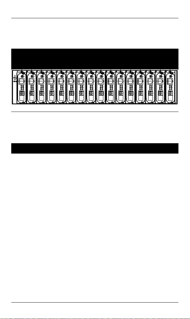
Front Panel Display
FRON T PANEL
The front panel of this ClearCube F6151 Media Converter Chassis
System shows it with sixteen media converters in bay 1~16.
There are two LED indicators on the left side of the front of the
chassis that indicate the status of each power supply.
Figure 2: Front panel of ClearCube F6151 Media Converter Chassis System
UNDERSTANDING LEDS
Power
Supply’s
Switch LED
Green Power switched on
Off
Power switched off
Blown fuse
Power supply failed
L Before you use this table for troubleshooting, make
sure the chassis system is properly connected to
power and switched on.
User’s Guide 3
Page 10

ClearCube F6151 Media Converter and Chassis System
Installation
Selecting a Site for the Equipment
As with any electric device, you should place the equipment where
it will not be subjected to extreme temperatures, humidity, or
electromagnetic interference. Specifically, the site you select
should meet the following requirements:
• The ambient temperature should be between 32 and 104
degrees Fahrenheit (0 to 40 degrees Celsius).
• The relative humidity should be less than 90 percent,
non-condensing.
• Surrounding electrical devices should not exceed the
electromagnetic field (RFC) standards for IEC 801-3, Level 2
(3V/M) field strength.
• Make sure that the equipment receives adequate ventilation.
Do not block the ventilation holes on each side of the switch
or the fan exhaust port on the side or rear of the equipment.
• The power outlet should be within 1.8 meters of the switch.
4 User’s Guide
Page 11

ClearCube F6151 Media Converter and Chassis System
Deciding How to Install the System
The accessories supplied in the product package include:
rackmount screws, rackmount brackets, and bracket screws.
This well-built chassis can be installed in the following ways:
MOUNTED TO 19-INCH STANDARD RACK
Use the rackmount brackets and screws to install the chassis into
any EIA 19” standard rack.
Step 1: Attach the brackets to each side of the chassis. Apply
Step 2: Carefully position the chassis into the rack. Align the
Step 3: Proceed to the “Connecting to Power” section.
DESKTOP OR ANY FLAT SURFACE
screws to each side and secure them tightly.
brackets to the side holes on the rack and use rack screws
to secure the chassis with the rack.
The chassis can sit on desktop or any flat surface with adequate
space and ventilation. If you want to place it onto a shelf, make
sure the shelf can withstand a minimum weight of 10kg.
Step 1: Simply put the chassis on the desired place.
Step 2: Ensure the chassis receives good ventilation.
Step 3: Proceed to the “Connecting to Power” section.
User’s Guide 5
Page 12

ClearCube F6151 Media Converter and Chassis System
Replacing Media Converters in a Chassis
The chassis is shipped containing 16 media converters. Each media
converter is attached to a media converter carrier, which is already
fitted into bays of the chassis.
The following steps describe how to attach a media converter
carrier to a media converter if you need to replace a media
converter.
Step 1: To install a media converter onto any of the carriers, you
have to unscrew the carrier from the desired bay first.
Step 2: Fit the media converter onto the carrier.
Step 3: When the media converter is completely seated onto the
carrier, insert the carrier to the guide rails of the bay slot.
Step 4: Carefully slide in the carrier until it is fully and firmly
fitted to the power socket. Fasten the screws on the carrier.
L
i. The chassis is designed to house only the proprietary
media converters.
ii. Never insert any media converter into the chassis
directly without using the supplied carriers. These
carriers allow secure and consistent placement of the
media converters into the chassis’ backplane without
causing any damage.
iii. For details, please refer to the User’s Manual for media
converters.
For more information about media converters, see “Media
Converter Overview” on page 9.
6 User’s Guide
Page 13

ClearCube F6151 Media Converter and Chassis System
Connecting to Power
POWER SUPPLY
The chassis ships with two power supplies. When the chassis is
equipped with two power supplies, you can have the following
advanced performance.
♦ Hot Swappable –
The design of the power system is based on an idea of
providing maximum flexibility and redundancy. In this way,
you may remove any of the two power supplies without
turning off the system.
♦ Redundancy –
During operation, both power supplies are switched on and
share the current load. In case that one of them should fail, the
other will instantaneously take 100% of the load without any
loss. Similarly, if one power supply is removed from servicing,
it can be switched off and removed while the chassis continues
functioning.
♦ Protection System –
The power of each converter bay comes from the two shared
power supplies. Each bay is isolated from each other under a
certain protection mechanism, so that it is free from any
problem that might occur to the power supplies or faulty
converter bay. This is the best solution to protect your
investment in media converters.
CONNECTING TO POWER
The chassis system is equipped with two power supplies.
Step 1: Connect the supplied AC power cord to the receptacle on
Step 2: Attach the plug into a standard AC outlet with a voltage
User’s Guide 7
the front panel of each power supply.
range from 100~240Vac.
Page 14

ClearCube F6151 Media Converter and Chassis System
Step 3: Turn on the chassis system by flipping the ON/OFF switch
beside the receptacle to ON position. The LEDs on the
front panel of the media converter chassis system will
come on then.
Figure 3: The rear of the ClearCube F6151 Media Converter Chassis
System
Cooling System
The chassis system can hold two power supplies and up to sixteen
media converters, and therefore, it is necessary to provide a good
cooling system to obtain adequate ventilation.
The chassis is equipped with two hot-swappable power supplies
with fans at the rear. The chassis is also equipped with one fan on
the left and right side of the chassis.
Figure 4: The rear side of the ClearCube F6151 Media Converter Chassis
System
8 User’s Guide
Page 15

ClearCube F6151 Media Converter and Chassis System
Media Converter Overview
The media converter provides one channel for media conversion
between 10/100BaseTX and 100BaseFX. Media converters are
installed in a standard 19” chassis as shown below.
Product Overview
Product Features
• One-channel media conversion between 10/100BaseTX and
100BaseFX
• Fiber media allows multi-mode fiber using SC connector
• Auto negotiation of speed and duplex mode on TX port
• Auto MDIX on TX port
• One DIP switch for configuring link-fault-pass-through, fixed
speed and half/full duplex
• Store-and-forward mechanism
• Non-blocking full wire-speed forwarding rate
• Support broadcast storm filtering
• Back-pressure & IEEE802.3x compliant flow control
• Front panel status LEDs
• External AC to DC power adapter
• Hot-swappable when used with a chassis
User’s Guide 9
Page 16

ClearCube F6151 Media Converter and Chassis System
One-Channel Media Converter
Ports
The Converter provides one TX port and one FX port. For the FX
port, it provides options of multi-mode fiber using an SC connector.
For the TX port, it uses RJ-45 connector, auto-MDIX, and auto
senses the speed of 10/100Mbps and full/half duplex.
Port Settings
Port settings are made very simple by means of a DIP (Dual Inline
Package) switch at the rear panel of the module.
1 2 3 4 5
6
DIP SWITCH
There are six pins on the DIP switch for port settings. Refer to the
table below for more details.
DIP
switch
No.
1 Enable link-fault-pass-
2 Enable auto negotiation for
3 TX port forced to 100Mbps TX port forced to 10Mbps
4 TX port forced to full duplex
5 FX port forced to full duplex
6
Down (Default Setting) Up
Disable link-fault-pass-
through
TX port
mode
mode
through
Enable forced mode for TX
port
TX port forced to half
duplex mode
FX port forced to half
duplex mode
10 User’s Guide
Page 17

ClearCube F6151 Media Converter and Chassis System
• First, disconnect the converter from the power. Then toggle
Pin 2 of the DIP switch to the up position to enable the forced
mode for TX port.
NOTE Pin 2 must be toggled up prior to speed and duplex
mode settings manually.
• Toggle down Pin 3 to force the TX port at the speed of
100Mbps. Or toggle up Pin 3 for 10Mbps speed.
• Toggle down Pin 4 to force the TX port at full duplex mode.
Or toggle up Pin 4 for half duplex mode.
• Toggle down Pin 5 to force the FX port at full duplex mode.
Or toggle up Pin 5 for half duplex mode.
• Connect the converter to the power again. The new setting will
come into effect then.
Front Panel & LEDs
LED INDICATORS
The LED indicators give you instant feedback on status of the
converter:
LEDs State Indication
PWR
100 (Mbps)
LNK/ACT
Steady Power on
PWR stands for POWER
Off Power off
Steady Connection at the speed of
100Mbps
Off Connection at the speed of 10Mbps
Steady A valid network connection
established
LNK stands for LINK
Flashing Transmitting or receiving data
ACT stands for ACTIVITY
User’s Guide 11
Page 18

ClearCube F6151 Media Converter and Chassis System
Off Neither valid network connection
established nor
transmitting/receiving data.
FDX/COL
Steady Connection in full duplex mode
FDX stands for FULL-DUPLEX
Flashing Collision occurred
COL stands for COLLISION
Off Connection in half-duplex mode
12 User’s Guide
Page 19

ClearCube F6151 Media Converter and Chassis System
Specifications
CHASSIS SYSTEM
Capacity
Power
Cooling
LED Indicators
Dimensions
Net Weight
POWER SUPPLY
Power Input
Power Output
Load
Operating
Temperature
Storage
Temperature
Emissions
MEDIA CONVERTER
Sixteen bays for housing up to sixteen
media converters
Tow power supplies provided, hotswappable
Two power supplies with fans
One fan on the left and right side of the
chassis
2 LEDs (1 LED for each power supply’s
power status)
W440 mm × D276 mm × H90 mm
Standard 19” size, 2 U
8.5kg approx. (Fully fitted with sixteen media
converters)
110~240Vac, 50~60Hz
12Vdc, 84W (x2) max.
7A (x2) max.
0°C to 40° C (32°F to 104°F)
-25°C to 70°C (-13°F to 158°F)
CE Class A, FCC part 15 Class A
Applicable
Standards
Fixed Ports
Speed
10BaseT
100BaseTX/FX
Switching
Method
User’s Guide 13
IEEE 802.3 10BaseT
IEEE 802.3u 100BaseTX & 100BaseFX
1 TX port, 1 FX port
10/20Mbps for half/full-duplex
100/200Mbps for half/full-duplex
Store-and-Forward
Page 20

ClearCube F6151 Media Converter and Chassis System
Forwarding rate
LED Indicators
Dimensions
Weight
Power
Power
Consumption
Operating
Temperature
Storage
Temperature
Humidity
Emissions
14,880/148,800pps for 10/100Mbps
Per Unit- (2 LEDs): Power; 100(Mbps)
Per Port- (2 LEDs): LNK/ACT; FDX/COL
L110 × W81 (max.) × H23 mm
190 g
External power adaptor 12VDC, 0.8A
7W Max.
0°C ~ 40°C (32°F ~ 104°F)
-25°C ~ 70°C (-13°F ~ 158°F)
10 ~ 90%, non-condensing
FCC part 15 Class A, CE Mark
14 User’s Guide
Page 21

ClearCube F6151 Media Converter and Chassis System
Suppor t
Email: support@clearcube.com
Web site: support.clearcube.com
Toll-free: (866) 652-3400
Phone: (512) 652-3400
User’s Guide 15
Page 22

ClearCube Technology, Inc.
8834 Capital of Texas Highway North Austin, Texas 78759 (512) 652-3500
www.clearcube.com
P/N G0400031 Rev A
 Loading...