

Page 1

C/Port and Multi Video Expander
User’s Guide
Page 2

Technical Support
Please refer to our support website for technical updates, additional warranty
information and documentation, and software revisions:
Web: http://support.clearcube.com
Email: support@clearcube.com
Phone: (512) 652-3400 or call toll free (866) 652-3400 (United States)
ClearCube Technology Corporate Headquarters
Mailing and Shipping Address:
The ClearCube Building
8834 Capital of Texas Hwy N.
Austin, Texas 78759
Email: info@clearcube.com
Main Phone: (512) 652-3500 or call toll free (866) 652-3500 (United States)
Main Fax: (512) 652-3501
Or your local ClearCube Reseller or Authorized Service Provider
Copyrights
©2005–2008 by ClearCube Technology Inc. All rights reserved. Under copyright laws,
this publication may not be reproduced or transmitted in any form, electronic or
mechanical, including photocopying, recording, storing in an information retrieval
system, or translating, in whole or in part, without the prior written consent of
ClearCube Technology, Inc.
This information is subject to change without notice and ClearCube shall not be liable
for any direct, indirect, special, incidental or consequential damages in connection
with the use of this material.
Trademarks
ClearCube™, Blade Switching BackPack™, PC Blade™, C/Port™, and I/Port™ are
trademarks of ClearCube Technology Inc. Product and company names mentioned
herein are trademarks or trade names of their respective companies.
Patents
The ClearCube Architecture and its components described in this user manual are
protected by numerous granted and pending U.S. and international patents.
Granted patents include: US05926172, US05966056, US05994952, US06012101,
US06020839, US06037884, US06038616, US06119146, US06148182,
US06167241, US06385666, US06421393, US06426970, US06633934,
US06708247, US06735658, and US06886055.
Patents pending include: US S/N 09/755378, US S/N 10/279475, US S/N 10/198719,
US S/N 10/198650, US S/N 10/409219, US S/N 09/728667, US S/N 09/728669, US
S/N 10/411804, US S/N 10/411908, US S/N 10/458853, US S/N 10/364584, US S/N
10/301536, US S/N 60/411066, US S/N 10/662933, US S/N 10/662889, US S/N
10/662932, US S/N 10/662968, US S/N 10/301563, US S/N 10/662936, US S/N
10/301518, US S/N 10/662955 and US S/N 10/662954.
Inquiries regarding patented technology should be directed to ClearCube Corporate
Headquarters.
Page 3

Contents
Preface . . . . . . . . . . . . . . . . . . . . . . . . . . . . . . . . . . . . . . . . . . . . . . . . . . . . . . . . . . . . . . . . . . . . . . . . . . . . . . . vii
How to Use this Guide . . . . . . . . . . . . . . . . . . . . . . . . . . . . . . . . . . . . . . . . . . . . . . . . . . . . . . . . . . . . . . . vii
FCC Warning . . . . . . . . . . . . . . . . . . . . . . . . . . . . . . . . . . . . . . . . . . . . . . . . . . . . . . . . . . . . . . . . . . . . . . vii
California Proposition 65 Statement . . . . . . . . . . . . . . . . . . . . . . . . . . . . . . . . . . . . . . . . . . . . . . . . . . . . . vii
WEEE Information . . . . . . . . . . . . . . . . . . . . . . . . . . . . . . . . . . . . . . . . . . . . . . . . . . . . . . . . . . . . . . . . . . vii
Warning Regarding Medical and Clinical Use of ClearCube Products . . . . . . . . . . . . . . . . . . . . . . . . . . viii
Symbols . . . . . . . . . . . . . . . . . . . . . . . . . . . . . . . . . . . . . . . . . . . . . . . . . . . . . . . . . . . . . . . . . . . . . . . . . . . viii
Safety Guidelines . . . . . . . . . . . . . . . . . . . . . . . . . . . . . . . . . . . . . . . . . . . . . . . . . . . . . . . . . . . . . . . . . . . . ix
Chapter 1. ClearCube C/Port Overview . . . . . . . . . . . . . . . . . . . . . . . . . . . . . . . . . . . . . . . . . . . . 1
C/Port . . . . . . . . . . . . . . . . . . . . . . . . . . . . . . . . . . . . . . . . . . . . . . . . . . . . . . . . . . . . . . . . . . . . . . . . . . . . . . . . . .1
Fiber Solution . . . . . . . . . . . . . . . . . . . . . . . . . . . . . . . . . . . . . . . . . . . . . . . . . . . . . . . . . . . . . . . . . . . . . . . . . . .3
C7420 Fiber C/Port . . . . . . . . . . . . . . . . . . . . . . . . . . . . . . . . . . . . . . . . . . . . . . . . . . . . . . . . . . . . . . . . . . . .3
F6150–160 Fiber Transceiver . . . . . . . . . . . . . . . . . . . . . . . . . . . . . . . . . . . . . . . . . . . . . . . . . . . . . . . . . . . .4
Multi-Video Expander . . . . . . . . . . . . . . . . . . . . . . . . . . . . . . . . . . . . . . . . . . . . . . . . . . . . . . . . . . . . . . . . . . . . .5
Cable Requirements . . . . . . . . . . . . . . . . . . . . . . . . . . . . . . . . . . . . . . . . . . . . . . . . . . . . . . . . . . . . . . . . . . . . . . .6
Chapter 2. C/Port Installation . . . . . . . . . . . . . . . . . . . . . . . . . . . . . . . . . . . . . . . . . . . . . . . . . . . . 9
Caution Statements . . . . . . . . . . . . . . . . . . . . . . . . . . . . . . . . . . . . . . . . . . . . . . . . . . . . . . . . . . . . . . . . . . . . . . .9
Setup . . . . . . . . . . . . . . . . . . . . . . . . . . . . . . . . . . . . . . . . . . . . . . . . . . . . . . . . . . . . . . . . . . . . . . . . . . . . . . .9
Orientation and Venting . . . . . . . . . . . . . . . . . . . . . . . . . . . . . . . . . . . . . . . . . . . . . . . . . . . . . . . . . . . . . . . .9
Power Sources . . . . . . . . . . . . . . . . . . . . . . . . . . . . . . . . . . . . . . . . . . . . . . . . . . . . . . . . . . . . . . . . . . . . . . . .9
C7130 and C7120 C/Port Installation . . . . . . . . . . . . . . . . . . . . . . . . . . . . . . . . . . . . . . . . . . . . . . . . . . . . . . . .10
Following Best Practices for Cabling and Monitors . . . . . . . . . . . . . . . . . . . . . . . . . . . . . . . . . . . . . . . . . .10
Identifying Your C/Port . . . . . . . . . . . . . . . . . . . . . . . . . . . . . . . . . . . . . . . . . . . . . . . . . . . . . . . . . . . . . . .10
Identifying your Chassis . . . . . . . . . . . . . . . . . . . . . . . . . . . . . . . . . . . . . . . . . . . . . . . . . . . . . . . . . . . . . . .11
Unpacking the C/Port . . . . . . . . . . . . . . . . . . . . . . . . . . . . . . . . . . . . . . . . . . . . . . . . . . . . . . . . . . . . . . . . .11
Installing the C/Port on the Desktop . . . . . . . . . . . . . . . . . . . . . . . . . . . . . . . . . . . . . . . . . . . . . . . . . . . . . .12
Tuning the C/Port . . . . . . . . . . . . . . . . . . . . . . . . . . . . . . . . . . . . . . . . . . . . . . . . . . . . . . . . . . . . . . . . . . . .14
Before Tuning a C/Port . . . . . . . . . . . . . . . . . . . . . . . . . . . . . . . . . . . . . . . . . . . . . . . . . . . . . . . . . . . . .15
Tuning a C7130 Connected to an R4300 Chassis . . . . . . . . . . . . . . . . . . . . . . . . . . . . . . . . . . . . . . . .15
Tuning a C7130 Connected to an R4200 Chassis . . . . . . . . . . . . . . . . . . . . . . . . . . . . . . . . . . . . . . . .15
Tuning a C7120 or Earlier Model Connected to an R4300 Chassis . . . . . . . . . . . . . . . . . . . . . . . . . . .16
Tuning a C7120 or Earlier Model Connected to an R4200 Chassis . . . . . . . . . . . . . . . . . . . . . . . . . . .16
Fine-Tuning Model C7130 C/Ports . . . . . . . . . . . . . . . . . . . . . . . . . . . . . . . . . . . . . . . . . . . . . . . . . . . . . . .16
Tuning Notes . . . . . . . . . . . . . . . . . . . . . . . . . . . . . . . . . . . . . . . . . . . . . . . . . . . . . . . . . . . . . . . . . . . . . . . .17
Using the C7130 Blade Reset Button . . . . . . . . . . . . . . . . . . . . . . . . . . . . . . . . . . . . . . . . . . . . . . . . . . . . .17
Using the Blade Reset Button on Earlier C/Ports . . . . . . . . . . . . . . . . . . . . . . . . . . . . . . . . . . . . . . . . . . . .17
Locking out Mass Storage Devices . . . . . . . . . . . . . . . . . . . . . . . . . . . . . . . . . . . . . . . . . . . . . . . . . . . . . . .18
iii
Page 4

C7420 Fiber C/Port Installation . . . . . . . . . . . . . . . . . . . . . . . . . . . . . . . . . . . . . . . . . . . . . . . . . . . . . . . . . . . . 20
Setting up the C7420 Fiber C/Port . . . . . . . . . . . . . . . . . . . . . . . . . . . . . . . . . . . . . . . . . . . . . . . . . . . . . . . 20
Understanding C7420 LED Indicators . . . . . . . . . . . . . . . . . . . . . . . . . . . . . . . . . . . . . . . . . . . . . . . . . . . 21
Configuring the C7420 Fiber C/Port . . . . . . . . . . . . . . . . . . . . . . . . . . . . . . . . . . . . . . . . . . . . . . . . . . . . . 21
Understanding Default Network Addresses . . . . . . . . . . . . . . . . . . . . . . . . . . . . . . . . . . . . . . . . . . . . . . . 22
Setting up Connections . . . . . . . . . . . . . . . . . . . . . . . . . . . . . . . . . . . . . . . . . . . . . . . . . . . . . . . . . . . . . . . 22
Direct Connection . . . . . . . . . . . . . . . . . . . . . . . . . . . . . . . . . . . . . . . . . . . . . . . . . . . . . . . . . . . . . . . . 22
DHCP Connection . . . . . . . . . . . . . . . . . . . . . . . . . . . . . . . . . . . . . . . . . . . . . . . . . . . . . . . . . . . . . . . . 24
Sentral Connection . . . . . . . . . . . . . . . . . . . . . . . . . . . . . . . . . . . . . . . . . . . . . . . . . . . . . . . . . . . . . . . 25
Chapter 3. MVX Installation . . . . . . . . . . . . . . . . . . . . . . . . . . . . . . . . . . . . . . . . . . . . . . . . . . . . 27
Hardware Installation . . . . . . . . . . . . . . . . . . . . . . . . . . . . . . . . . . . . . . . . . . . . . . . . . . . . . . . . . . . . . . . . . . . . 27
Installing the Video Adapter . . . . . . . . . . . . . . . . . . . . . . . . . . . . . . . . . . . . . . . . . . . . . . . . . . . . . . . . . . . 27
Installing the MVX . . . . . . . . . . . . . . . . . . . . . . . . . . . . . . . . . . . . . . . . . . . . . . . . . . . . . . . . . . . . . . . . . . 27
Software Installation and Configuration . . . . . . . . . . . . . . . . . . . . . . . . . . . . . . . . . . . . . . . . . . . . . . . . . . . . . 29
Removing Outdated NVIDIA Drivers . . . . . . . . . . . . . . . . . . . . . . . . . . . . . . . . . . . . . . . . . . . . . . . . . . . . 29
Installing the NVIDIA Driver . . . . . . . . . . . . . . . . . . . . . . . . . . . . . . . . . . . . . . . . . . . . . . . . . . . . . . . . . . 30
Important Notes about MVX . . . . . . . . . . . . . . . . . . . . . . . . . . . . . . . . . . . . . . . . . . . . . . . . . . . . . . . . . . . . . . 34
Appendix A. Troubleshooting . . . . . . . . . . . . . . . . . . . . . . . . . . . . . . . . . . . . . . . . . . . . . . . . . . 37
C/Ports . . . . . . . . . . . . . . . . . . . . . . . . . . . . . . . . . . . . . . . . . . . . . . . . . . . . . . . . . . . . . . . . . . . . . . . . . . . . . . . 37
Red link status indicator on PC blade and C/Port . . . . . . . . . . . . . . . . . . . . . . . . . . . . . . . . . . . . . . . . . . . 37
No link status indicator light . . . . . . . . . . . . . . . . . . . . . . . . . . . . . . . . . . . . . . . . . . . . . . . . . . . . . . . . . . . 37
Poor video quality . . . . . . . . . . . . . . . . . . . . . . . . . . . . . . . . . . . . . . . . . . . . . . . . . . . . . . . . . . . . . . . . . . . 37
Loss of peripheral devices (USB) . . . . . . . . . . . . . . . . . . . . . . . . . . . . . . . . . . . . . . . . . . . . . . . . . . . . . . . 38
No video or link lights at desktops and no power to blades . . . . . . . . . . . . . . . . . . . . . . . . . . . . . . . . . . . 38
MVX . . . . . . . . . . . . . . . . . . . . . . . . . . . . . . . . . . . . . . . . . . . . . . . . . . . . . . . . . . . . . . . . . . . . . . . . . . . . . . . . . 38
No video is present . . . . . . . . . . . . . . . . . . . . . . . . . . . . . . . . . . . . . . . . . . . . . . . . . . . . . . . . . . . . . . . . . . 38
The monitor’s Auto-Adjust does not give a clear, sharp image . . . . . . . . . . . . . . . . . . . . . . . . . . . . . . . . 38
The video signal is lost after changing display settings . . . . . . . . . . . . . . . . . . . . . . . . . . . . . . . . . . . . . . 38
Fiber Optic Troubleshooting . . . . . . . . . . . . . . . . . . . . . . . . . . . . . . . . . . . . . . . . . . . . . . . . . . . . . . . . . . . . . . 39
No video and/or digital link present . . . . . . . . . . . . . . . . . . . . . . . . . . . . . . . . . . . . . . . . . . . . . . . . . . . . . 39
The monitor’s Auto-Adjust does not give a clear, sharp image . . . . . . . . . . . . . . . . . . . . . . . . . . . . . . . . 39
Technical Support . . . . . . . . . . . . . . . . . . . . . . . . . . . . . . . . . . . . . . . . . . . . . . . . . . . . . . . . . . . . . . . . . . . . . . 39
Appendix B. Specifications . . . . . . . . . . . . . . . . . . . . . . . . . . . . . . . . . . . . . . . . . . . . . . . . . . . . 41
C/Port . . . . . . . . . . . . . . . . . . . . . . . . . . . . . . . . . . . . . . . . . . . . . . . . . . . . . . . . . . . . . . . . . . . . . . . . . . . . . . . . 41
C7420 Fiber C/Port . . . . . . . . . . . . . . . . . . . . . . . . . . . . . . . . . . . . . . . . . . . . . . . . . . . . . . . . . . . . . . . . . . . . . 42
MVX . . . . . . . . . . . . . . . . . . . . . . . . . . . . . . . . . . . . . . . . . . . . . . . . . . . . . . . . . . . . . . . . . . . . . . . . . . . . . . . . . 42
Appendix C. Regulatory Compliance . . . . . . . . . . . . . . . . . . . . . . . . . . . . . . . . . . . . . . . . . . . . 43
ElectroMagnetic Compatibility (EMC) . . . . . . . . . . . . . . . . . . . . . . . . . . . . . . . . . . . . . . . . . . . . . . . . . . . 43
Emissions (Radio Frequency Interference) . . . . . . . . . . . . . . . . . . . . . . . . . . . . . . . . . . . . . . . . . . . . . . . . 43
Electro-Magnetic Interference (EMI) Immunity . . . . . . . . . . . . . . . . . . . . . . . . . . . . . . . . . . . . . . . . . . . . 43
Power Harmonics and Flicker . . . . . . . . . . . . . . . . . . . . . . . . . . . . . . . . . . . . . . . . . . . . . . . . . . . . . . . . . . 44
Safety Compliance . . . . . . . . . . . . . . . . . . . . . . . . . . . . . . . . . . . . . . . . . . . . . . . . . . . . . . . . . . . . . . . . . . . 44
CE Marking . . . . . . . . . . . . . . . . . . . . . . . . . . . . . . . . . . . . . . . . . . . . . . . . . . . . . . . . . . . . . . . . . . . . . . . . 44
iv
Page 5

Declaration of Conformity . . . . . . . . . . . . . . . . . . . . . . . . . . . . . . . . . . . . . . . . . . . . . . . . . . . . . . . . . . . . .45
C7420 Fiber C/Port and F6150–160 Fiber Transceiver . . . . . . . . . . . . . . . . . . . . . . . . . . . . . . . . . . . . . . . . . .46
ElectroMagnetic Compatibility (EMC) . . . . . . . . . . . . . . . . . . . . . . . . . . . . . . . . . . . . . . . . . . . . . . . . . . . .46
Emissions (Radio Frequency Interference) . . . . . . . . . . . . . . . . . . . . . . . . . . . . . . . . . . . . . . . . . . . . . . . . .46
Electro-Magnetic Interference (EMI) Immunity . . . . . . . . . . . . . . . . . . . . . . . . . . . . . . . . . . . . . . . . . . . . .46
Power Harmonics and Flicker . . . . . . . . . . . . . . . . . . . . . . . . . . . . . . . . . . . . . . . . . . . . . . . . . . . . . . . . . . .47
Safety Compliance . . . . . . . . . . . . . . . . . . . . . . . . . . . . . . . . . . . . . . . . . . . . . . . . . . . . . . . . . . . . . . . . . . .47
CE Marking . . . . . . . . . . . . . . . . . . . . . . . . . . . . . . . . . . . . . . . . . . . . . . . . . . . . . . . . . . . . . . . . . . . . . . . . .47
Declaration of Conformity . . . . . . . . . . . . . . . . . . . . . . . . . . . . . . . . . . . . . . . . . . . . . . . . . . . . . . . . . . . . .47
v
Page 6

vi
Page 7

Preface
How to Use this Guide
Thank you for purchasing your quality ClearCube products. The ClearCube Architecture was
developed to bring you unprecedented levels of manageability, security, reliability, and space
savings. The ease of use of ClearCube’s products makes installation straightforward.
This manual provides all the product and installation information needed to set up and run
ClearCube Technology’s C/Port Architecture for managed desktop environments. We
recommend that you familiarize yourself with the ClearCube Architecture and product
descriptions and read through the entire installation and setup procedures before beginning
installation.
If you encounter any problems, please contact our Technical Support using the contact
information provided on the inside front cover of this manual.
FCC Warning
This equipment generates and uses radio frequency energy and, if not installed and used in
strict accordance with the instructions in this manual, may cause interference to radio and
television reception. Changes or modifications not expressly approved by ClearCube
Technology could void the user's authority to operate the equipment under the FCC Rules.
California Proposition 65 Statement
WARNING: ClearCube products contain chemicals, including lead, known to the State of
California to cause cancer, birth defects, or other reproductive harm. Wash hands after
handling.
ClearCube products should be disposed of in accordance with local laws governing computer
equipment disposal.
WEEE Information
The products described in this document are subject to regulation under the European Union
Directive 2002/96/EC, that mandates separate waste collection, treatment, and recycling of
electronic products. This directive is commonly known as WEEE, for Waste from Electrical
and Electronic Equipment, and its intent is to promote the safe and sensible disposal of
products that have outlived their usefulness.
The “crossed-out” trash bin symbol, shown to the left, identifies products that should be
recycled, not simply discarded. ClearCube Technology supports the reuse, recycling,
recovery, and responsible disposal of all products, not just our systems.
Preface • vii
Page 8
ClearCube Technology is committed to meeting the requirements of the European Union
WEEE Directive and is currently developing country-specific implementation plans that
comply with the WEEE legislation. The goal of the directive is to reduce the environmental
impact due to the disposal of electrical and electronic equipment that has reached the end of its
useful service life. This directive goes into enforcement on August 13, 2005.
ClearCube products are sold exclusively to commercial and industrial customers and not to
private households. Under the WEEE legislation terms, commercial and industrial customers
have the responsibility to ensure that all electrical and electronic equipment is disposed of
properly and in accordance with all applicable laws and local regulations. For more
information, visit the ClearCube Technology web site at www.clearcube.com
recycle@clearcube.com
, or call at (866) 652-3400 or +1 (512) 652-3400.
, email at
Materials used in this product, if not disposed of properly, could have adverse effects on the
environment and human health. Do not dispose of these products in unsorted municipal waste
containers. Deliver electronic waste only to an approved recycling, and/or treatment facility. If
one is not available, contact ClearCube for assistance.
Warning Regarding Medical and Clinical Use of ClearCube
Products
ClearCube products are not designed with components and testing for a level of reliability
suitable for use in or in connection with surgical implants or as critical components in any life
support systems whose failure to perform can reasonably be expected to cause significant
injury to a human. Applications of ClearCube products involving medical or clinical treatment
can create a potential for death or bodily injury caused by product failure, or by errors on the
part of the user. Because each end-user system environment is customized and differs from
ClearCube testing platforms and because a user may use ClearCube products in combination
with other products in a manner not evaluated or contemplated by ClearCube, the user is
ultimately responsible for verifying and validating the suitability of ClearCube products
whenever ClearCube products are incorporated in a system, including, without limitation, the
appropriate design, process and safety level of such system or application.
viii • Preface
Symbols
Symbols are used on the equipment to convey specific information to the operator and service
person. It is important to understand the intended meaning of these symbols. Below are the
graphical symbols that are used on ClearCube Technology, Inc. Products and their meaning.
Refer to Manual
Used on the equipment’s rating label to direct the operator or service person to the manual for additional information.
Stand By
One symbol used for each blade installed located on front of the
chassis. Soft Start switch used to power on that particular blade.
Page 9
Fuse
Located on equipment rating label. Symbol is accompanied with
the specifications needed for replacement. Only qualified technicians should perform this operation.
Protective Earth Terminal
Identifies the terminal that is used to connect all metal parts of the
enclosure through an external conductor to ground for the protection against electrical shock in a fault condition.
Equipment Protection Class II
May be located on the power adapter’s rating label. Indicates that
equipment is double insulated from hazardous voltages. Not to be
confused with “Class 2” that is a US National Electrical Code (NEC)
circuit classification.
These same symbols are used within this document where appropriate to indicate situations
that merit checking this or another manual, or situations that could result in damage to
equipment or physical injury.
CAUTION: A Caution notice in this manual indicates that equipment damage
or minor injury may result if proper procedures are not followed.
WARNING – A Warning notice
equipment damage, or serious injury including death may result if proper
procedures are not followed.
in this manual indicates that catastrophic
Safety Guidelines
Before undertaking any troubleshooting or maintenance procedure, read carefully all
WARNING and CAUTION notices. This equipment contains voltage hazardous to human
life and is capable of inflicting personal injury.
• Installations – ClearCube equipment is required to be installed in accordance with the
local electrical codes and may be subject to inspection by the authority having jurisdiction.
• Chassis Grounding – ClearCube’s chassis and Fiber Transceiver has been designed with
a three-conductor IEC 60320 appliance inlet that – with the proper power cord – connects
the building’s external protective earthing conductor to all accessible metal parts of the
enclosure. To minimize shock hazard, make sure your electrical power outlet has an
appropriate earth safety ground that is connected each time you power on the equipment.
—Apparaten skall anslutas till jordat uttag när den anslutas till ett nätuerk.—
• Power Cord Selection – ClearCube or ClearCube’s Distributors provides power cords
that are specifically designed for use with that particular piece of equipment and are
approved for use by the local authority having jurisdiction in the country where the
Preface • ix
Page 10
equipment is put into service. Please refer to the installation sections of this manual for
specific power cord requirements. For replacement of power cords, refer to Appendix C –
Technical Support.
• Power Adapters – ClearCube or ClearCube’s Distributors provides power adapters that
are specifically designed for use with that particular piece of equipment and are approved
for use by the local authority having jurisdiction in the country where the equipment is put
into service. Please refer to the installation sections of this manual for specific power cord
requirements. For replacement of power cords, refer to Appendix C – Technical Support.
• IT Power Systems – ClearCube equipment has been evaluated and found to be
compatible with IT power distribution systems with a phase-to-phase voltage not to
exceed 240 V.
• Live Circuits – Operating personnel and service personnel must not remove protective
covers when operating the ClearCube chassis. Adjustments and service to internal
components must be undertaken by qualified service technicians. During any service of
this product other than replacing a PC blade or the fan tray, the main connector to the
premise wiring must be disconnected. Dangerous voltages may be present under certain
conditions. Use extreme caution.
• Explosive Atmosphere – Do not operate the chassis in conditions where flammable gases
are present. Under such conditions this equipment is unsafe and may ignite the gases or
gas fumes.
• Part Replacement – Only service equipment with parts that are exact replacements, both
electrically and mechanically. Contact ClearCube Technology for replacement part
information. Installation of parts that are not direct replacements will void the warranty
and may cause harm to personnel operating the chassis. Furthermore, damage or fire may
occur if replacement parts are unsuitable.
• Modification – Do not modify any part of the C/Port, chassis, or PC blade from its
original condition. Modifications may result in hazards.
• Laser Safety – The Fiber Transceiver and the Fiber C/Port have been evaluated and
certified to an EN 60825-1 – Safety of laser products.
x • Preface
ClearCube Technology products that use lasers display the following graphic on the rating
label:
Marked devices comply with the FDA code of Federal 21 CFR 1040 per Notice 50 and/or the
Canadian Radiation Emitting Devices Act REDR C1370.
CAUTION: Use of controls or adjustments or performance of procedures
other than those specified herein may result in hazardous radiation
exposure.
Page 11

Chapter 1. ClearCube C/Port Overview
The ClearCube architecture delivers Intel-based PC functionality to the desktop from a secure,
centralized location. This results in dramatic increases in manageability and security while
providing mission-critical reliability, performance, and uptime improvements with lowered
costs. Replacing a traditional PC box with a ClearCube C/Port or I/Port in an office or cubicle
also saves space, eliminates fan noise and simplifies cabling resulting in a clear cube. The key
components of the ClearCube Architecture are:
• PC Blade – a remotely-located, Intel-based computer in a dense form factor.
• Chassis – a centralized PC blade housing that provides the power for each PC blade and
accepts a wide variety of chassis modules.
• Chassis Module – a modular interface card that plugs into a chassis and provides user
port, management, and network connections.
• User Port – a remote desktop unit (C/Port or I/Port) to which standard peripherals are
connected.
• System Management – ClearCube Management Suite software and monitoring hardware
that is built into the blades, chassis, and user ports.
C/Port
This guide is devoted to the following C/Ports:
• C/Port – Copper-connected user port
• Fiber C/Port – Optical fiber-connected user port
• Multi-Video Expander (MVX) – Optional accessory that connects to a C/Port or Fiber
C/Port and allows using as many as four monitors at the desktop (optional video card may
be required).
The C/Port, shown in Figure 1 on page 2, is a desktop unit to which a user’s standard
peripherals are connected. The C/Port supports a 200–meter (660–foot) maximum connection
distance from the blade and has two USB ports, PS/2 mouse and keyboard ports, speaker and
microphone ports and video output port. Other C/Port options such as the Multi-Video
Expander (MVX) are also available from ClearCube.
C/Port • 1
Page 12
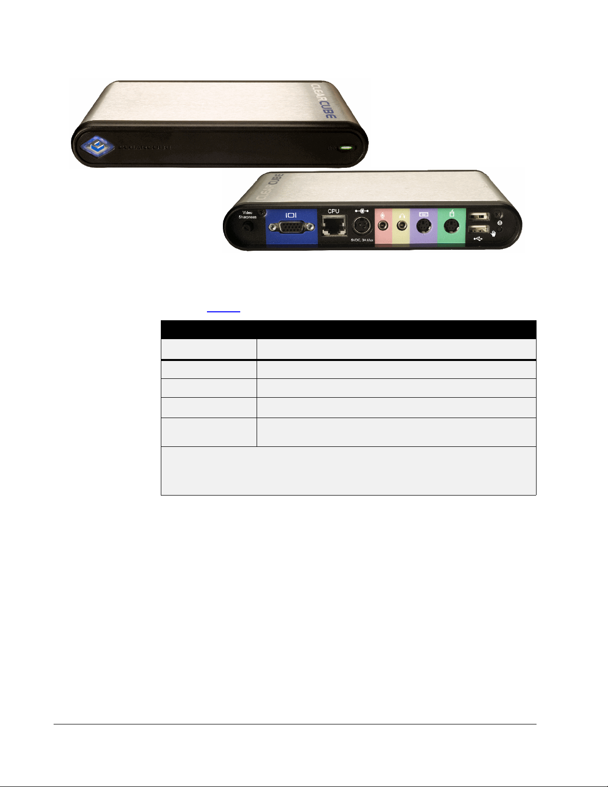
Figure 1. ClearCube C/Port
C/Ports are connected via standard twisted-pair copper networking cables: CAT5, CAT5e,
CAT6, or CAT6e. Table 1
Cable Type Distance
CAT5 660 feet (200 meters)
CAT5e 660 feet (200 meters)
CAT6 * C7130: 330 feet (100 meters)
lists the distance limits for C/Port installations.
Table 1. C/Port Connection Limits
CAT6, CAT6e *
Cable certified for 45 nS / 100 meters delay skew or less.
*
Cable certified for 25 nS / 100 meters delay skew or less.
* *
Note: C/Port connections use all four twisted pairs in a straight-through connection.
Note: When configuring an Admin Daisy Chain connecting 9 or more R4300 chassis, the
Admin C/Port must be located within 100 meters of the equipment rack if using CAT5
or CAT5e cable, or within 50 meters of the equipment rack if using CAT6e. When the
Admin Daisy Chain has 8 R4300 chassis or fewer, or is composed entirely of R4200
chassis, the standard distance lengths for C/Port cabling apply.
C7120 or earlier: 330 feet (100 meters)
*
C7130: 660 feet (200 meters)
2 • ClearCube C/Port Overview
Page 13

Fiber Solution
This section describes:
• C7420 Fiber C/Port
• F6150–160 fiber transceiver
C7420 Fiber C/Port
The C7420 is connected to an F6150–160 fiber transceiver, and the fiber transceiver is
connected to ClearCube PC blades. When deployed using a secure point-to-point fiber
connection, data displayed to the desktop does not commingle with any network traffic, and
users cannot disconnect the fiber desktop for use with a PC or notebook. C7420 does not
require special OS drivers.
The C7420 securely extends user desktops from centralized PC blades. This point-to-point
fiber optic solution supports existing fiber cabling infrastructures that employ a pair of
multi-mode fibers for each user. On the back-end, the C7420 connects to a F6150 fiber
transceiver chassis using a pair of 62.5µm or 50µm, multi-mode fibers through an LC connector.
ClearCube’s digital fiber optic extension technology leverages PCoIP™ technology to deliver:
• High-end PC experience for up to two monitors. You can configure each monitor
independently, specifying resolution and portrait or landscape orientation.
• Transparent USB redirection from the C7420 back to the PC blade. Standard peripheral
connections include:
– USB (including isochronous USB devices)
– HD audio input and output
– Digital and analog video
• Standard PC blade connection up 2,000 meters or greater
• Small form factor pluggable (SFP) single or multimode fiber optic modules
Fiber Solution • 3
Page 14
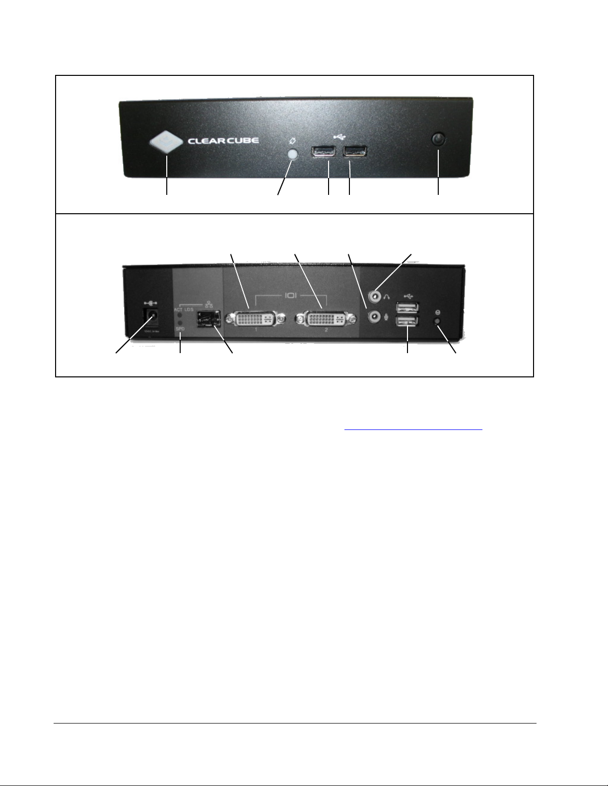
Front
Power Indicator LED
Power
Connector
For more information about setting up your C7420, about connecting devices to the C7420,
and about understanding the indicator LEDs, see "C7420 Fiber C/Port Installation
page 20.
F6150–160 Fiber Transceiver
Fiber
Activity
Link Indicator
USB 1.1 Ports
Rear
LC Fiber
Figure 2. C7420 Fiber C/Port
Power Button
Audio In Audio OutDVI–I Port 1 DVI–I Port 2
USB 1.1
Ports
Remote Blade
Power Button
" on
The F6150–160 fiber transceiver converts signals sent between C7420 Fiber C/Ports and PC
blades. The F6150–160 provides the following features:
• 2U–chassis compatible with standard, 19–inch racks
• Sixteen F6151 media converters that convert 10/100BASE–TX to 100BASE–FX
• Front–panel LEDs indicating power status, link status, connection speed, connection
mode, activity status, and collision status
• Hot–swappable media converters
• Hot–swappable, redundant, load–sharing power supplies
For more information about the F6150–160 fiber transceiver, see the Quick Start Guide and
the User’s Guide included with the transceiver.
4 • ClearCube C/Port Overview
Page 15
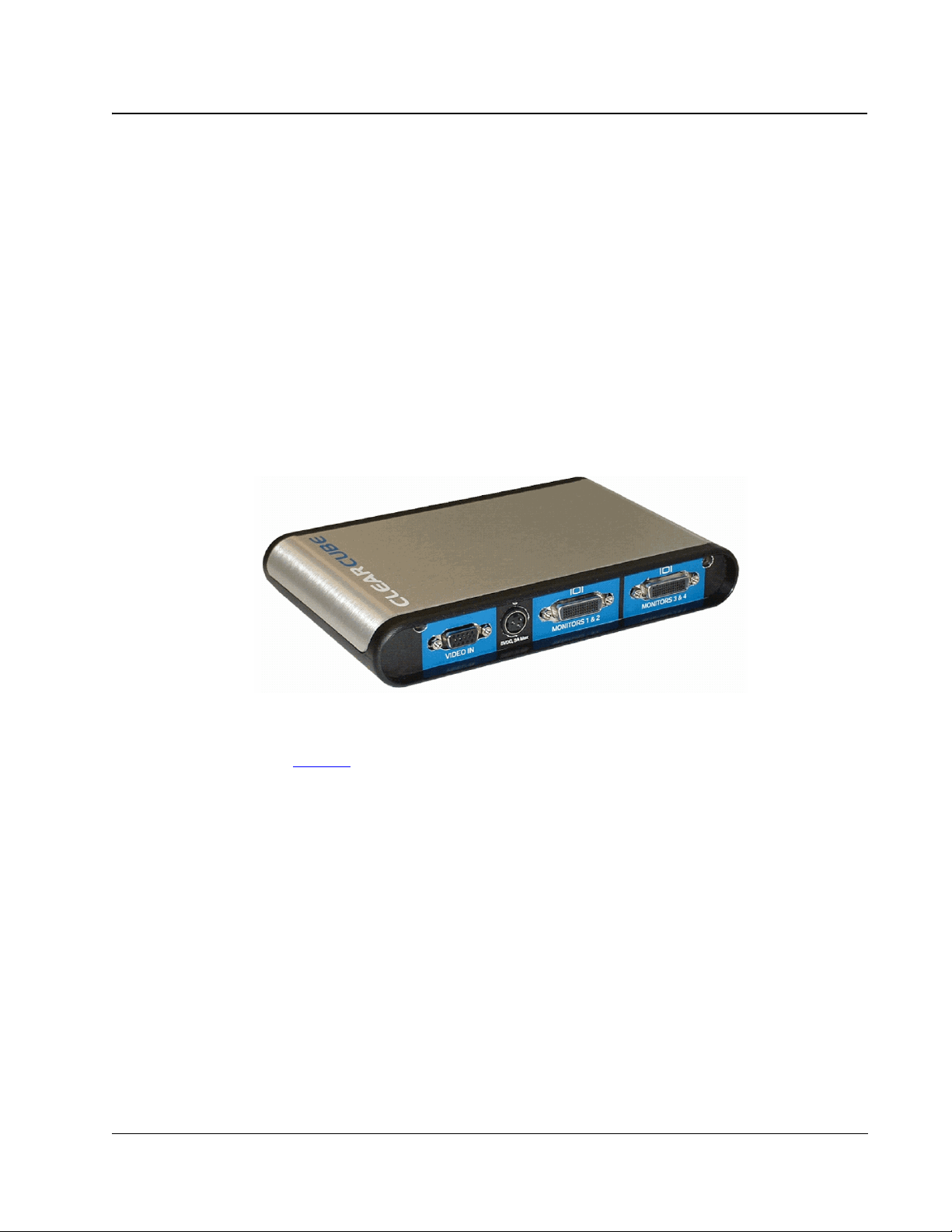
Multi-Video Expander
The ClearCube Multi-Video Expander (MVX) provides a revolutionary way to multi-task and
process information.
While the C/Port provides all the peripheral and USB connections, the multiplexed video
signal can be passed through to the MVX via a noise-limiting VGA connector cable. The
MVX distributes the individual video frames to the appropriate output connectors. The two
video outputs on the MVX are special, high-density connectors that can each drive two
monitors.
The MVX can be used with either the standard C/Port or the Fiber C/Port for connection over
copper or fiber optic cable (the MVX does not function with I/Ports). The MVX requires that
the PC blade have a multi-monitor graphics card and ClearCube-customized NVIDIA video
drivers installed. The centralized ClearCube architecture combined with multi-video
capabilities results in the ideal solution for space-constrained trading floors and other
applications requiring multiple displays.
Figure 3. ClearCube MVX Rear View
Shown in Figure 3
and can be stacked on top of a C/Port.
The ClearCube multi-video solution offers these features:
• Support for as many as four displays over a single C/Port cable or 62.5 micron,
multi-mode fiber
• NVIDIA-based graphics adapter for PC blade
• ClearView™ video driver/GUI based on NVIDIA’s award-winning nView video driver
• Analog and digital output (DVI) that provides resolution as high as 1280 x 1024 on each
monitor
on this page, the MVX is physically the same size as the standard C/Port
Multi-Video Expander • 5
Page 16
Cable Requirements
The ClearCube chassis uses standard network cables with RJ45 connectors to connect to
C/Ports and to an Ethernet network. These can be CAT5, CAT5e, CAT6, or CAT6e cables.
C/Ports require straight-through cables with all four twisted pairs available. See Table 1
page 2 for a maximum distance chart for these cables for C/Ports. Network connections follow
standard Ethernet guidelines. In practice, identical copper media can be used for C/Ports and
for network connections, although ClearCube recommends using different cable colors for
C/Port and network connections to simplify installation and maintenance. Throughout this
guide, “C/Port cable” and “network cable” refer interchangeably to copper-media cable such
as CAT5, CAT5e, CAT6, or CAT6e.
Note: Obtaining the maximum cable distance requires the use of cables with a delay skew
specification of < 25 nS / 100m. CAT6e cables generally meet this requirement, but a
majority of CAT6 cables do not.
Each fully loaded chassis requires eight C/Port cables with RJ-45 connectors for connections
to C/Ports at the desktop and eight network cables for blade connections to the Ethernet
network hub or switch. Additionally, short color-coded C/Port cables (Green for Chassis
Management & Control, Red for Sparing, and Yellow for Admin Port) are provided to
configure and daisy-chain your chassis.
Note: The C/Port cable connections use all four-wire pairs for the connection from the PC
blade to the C/Port. If your installation currently splits out wire pairs for multiple uses,
you must ensure that all four twisted pairs are available for each blade to C/Port
connection.
on
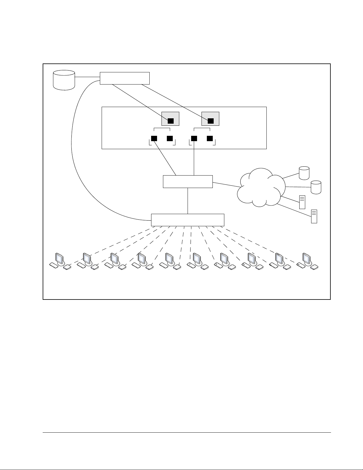
Figure 4 on this page provides schematics of the cabling required to connect your chassis to
user ports and your Ethernet network.
Data CenterUser Desktops
with C/Ports
Admin C/Port
and Terminal
Homerun
C/Port Cables
Figure 4. C/Port Architecture Cabling Diagram
Chassis
Network
Switch
Ethernet
Cables
6 • ClearCube C/Port Overview
Page 17
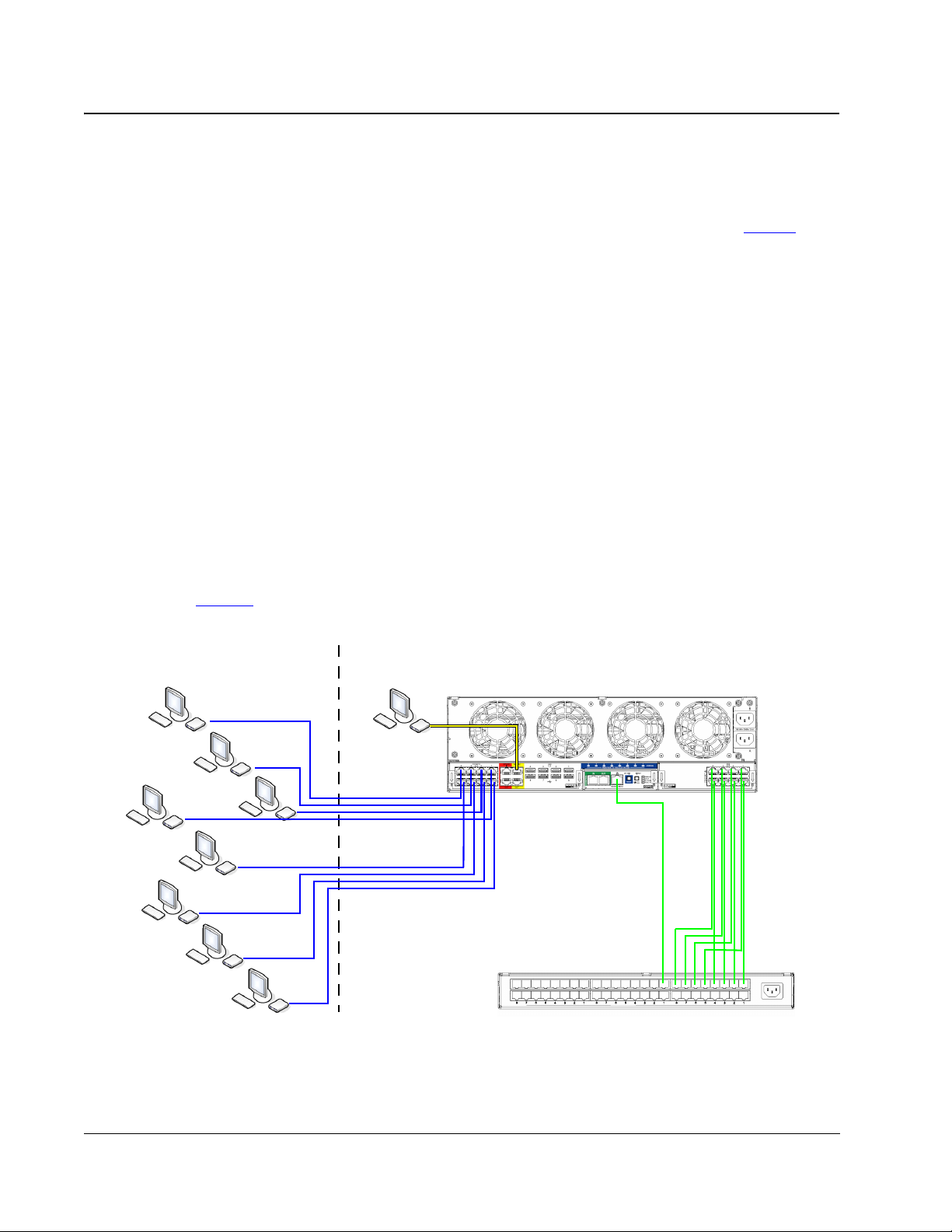
The following figure shows a typical cabling configuration to connect C7420 Fiber C/Ports to
an A3100 chassis. Note the recommended configuration, where the data network is separated
from the PCoIP network.
Sentral
Server
Sentral Switch
. . . .
PCoIP
PRI
SEC
BLADE 5
Network Switch
Fiber Transceiver
Fiber Connections
A3100 Chassis with 10 A1410 Blades
PCoIP
. . . .
PRI
SEC
BLADE 6
External Data Sources
Data
Network
and Entities
C7420 Fiber C/Ports and Peripherals
Figure 5. C7420 Cabling Diagram
Cable Requirements • 7
Page 18

8 • ClearCube C/Port Overview
Page 19

Chapter 2. C/Port Installation
Caution Statements
Improper connection, mounting, or use of this product could result in component failure or
undesired interference. Read the following caution statements before setting up and operating
your C/Port.
Setup
• Do not connect to AC power until all other connections are made, including the power
adapter. Connecting or disconnecting components or equipment on the back panel when
the C/Port is receiving AC power can cause power surges and damage the device.
• Do not force a connector into its socket. If any undue resistance is encountered, ensure that
the connector is correctly oriented to the receptacle.
• Do not attach the C/Port to a telephone jack or other powered network connection. This
will permanently damage the C/Port. This damage is not covered under the ClearCube
Technology limited warranty.
• Do not connect or disconnect USB devices or other peripherals during either the C/Port or
the blade start-up sequence. Unpredictable results will occur.
Orientation and Venting
Allow sufficient space around the C/Port for ventilation. Do not place the device in any
enclosure that restricts airflow around the device. Do not place any objects on the device.
Product environmental specifications are listed on page Appendix B. "Specifications"
page 41.
on
Power Sources
• To ensure regulatory compliance, use only the power supply included in the shipping
carton with the C/Port, or a ClearCube-approved equivalent.
• Surge protectors for electrical devices are recommended in areas of frequent lightning.
However, when lightning is occurring, your equipment should be properly shut down and
unplugged from AC power until the storm has passed.
Caution Statements • 9
Page 20

C7130 and C7120 C/Port Installation
The model C7130 C/Port provides automatic sharpness tuning that simplifies installation.
When connected to an R4300 chassis, the C7130 also provides a color Auto-tune feature that
greatly simplifies initial video configuration on the desktop.
Previous C/Ports require manual sharpness and color configuration on all chassis models.
C7130 C/Ports also require manual color configuration when connected to R4200 chassis
models, but provide automatic sharpness tuning. Any model of C/Port can always be manually
tuned.
Key elements in installing a C/Port include:
• Following best practices in monitor selection and cable layout
• Knowing which C/Port you are installing
• Knowing whether you are connecting to an R4300 chassis.
Understanding these elements will simplify and speed your installation.
Following Best Practices for Cabling and Monitors
C/Port cables should be routed from the data center to the desktop in as straight a line as is
reasonable, and should be separated from noise sources such as fluorescent lights, power
cables, and other signal cables whenever possible. Do not place power cables in the same
cable tray with C/Port cables, and follow applicable building and electrical codes when
installing cables. Use high-quality cables. See Table 1
cable specifications and maximum recommended cable lengths.
on page 2 for more information on
Before adjusting your C/Port for sharpness and color, set your monitor resolution and refresh
rate on the PC blade by using the controls provided with your operating system. To access
these controls for Windows operating systems, right-click in an open space on your desktop,
choose Properties, and then click on the Settings tab.
Video quality may be subjective, based on user preferences and the limitations of the monitor.
A higher quality monitor usually provides better video results. For best results with an LCD
monitor, set the monitor to its native resolution and press its Auto-Adjust button after video is
displayed.
Identifying Your C/Port
C/Ports are labeled on the bottom, and have their color switches set to the factory default
setting for easiest installation. See Figure 8
information. The procedures for installing all C/Ports are essentially the same. The differences
are in video tuning, and are described later in this section.
10 • C/Port Installation
on page 13 and Figure 9 on page 13 for more
Page 21

Identifying your Chassis
R4300 and R4200 chassis can easily be identified in your data center. Figure 6 on this page
shows R4300 and R4200 chassis. Note the difference in the connectors on the lower apron.
Figure 6. R4300 Chassis (L) and R4200 Chassis (R)
Unpacking the C/Port
The C/Port package contains one of each of the following items:
• C/Port unit
• C/Port power supply and power cord
A special tuning tool for adjustments is included with the documentation and software
package in your shipment. A mounting adapter is available as an option from ClearCube to
conveniently mount a C/Port underneath a desktop. Figure 7
features on the front and back panels of the C/Port.
on page 12 shows the major
C7130 and C7120 C/Port Installation • 11
Page 22

Power Indicator
(Blue Light
Around Badge)
C/Port Link Status
(Green = link, Red = no link)
DC Power Input
Microphone
Input
Audio
Output
Keyboard Port
Mouse Port
USB (2 Ports)
Blade
Reset/Power
Button
Video Sharpness
Adjustment Dial
Blade Connection (RJ-45)
Video Output
Figure 7. C/Port Front and Back Panels
Installing the C/Port on the Desktop
If you do not have easy access to the data center to determine whether you are connecting to an
R4300 or R4200 chassis, use the simple matrix shown in Table 2
procedure. If you are unsure of the chassis type to which the C/Port connects, use the manual
tuning procedures.
Table 2. C/Port Tuning Procedure
R4300 Chassis R4200 Chassis
to choose your tuning
To install a C/Port, do the following:
1. Verify the type of C/Port you are installing by reading the label on the bottom of the
C/Port.
a. If you are installing a C7130, verify that the three color switches on the bottom of the
b. If you are installing an earlier model, verify that the three color switches on the bottom
12 • C/Port Installation
C7130 C/Port Auto-Tune
Sharpness and Color
C7120 or earlier
C/Port
Manual Tune
Sharpness and Color
Auto-Tune Sharpness,
Manual Tune Color
Manual Tune
Sharpness and Color
C7130 are set to the positions marked F. This switch setting enables Auto-tuning on
the C7130. Use the C/Port tuning tool or a small flat-blade screwdriver to change the
switches, if necessary. See Figure 8
on page 13.
of the C/Port are set to the positions marked 1. This switch setting enables manual
tuning on all C/Ports. Adjust the switches if necessary. See Figure 9
on page 13.
Page 23

C
A
E
8
6
0
2
4
C
A
E
8
6
0
2
4
C7130
C7130 Auto-Tune
Default Setting
(F, not marked)
Figure 8. C7130 C/Port Color Switches
Universal C/Port II
C7110
C7130 Manual Tune
Setting
(1, not marked)
4
6
2
C7110 / C7120 C/Port
8
0
Default Setting
(1, not marked)
Figure 9. C/Port Color Switches, Earlier Versions
2. Locate your C/Port in a ventilated area away from any heat sources. Do not stack your
C/Port on top of monitor ventilation vents or on top of other significant heat generating
devices.
If you ordered the C/Port mounting kit, attach it to the desktop surface with screws or with
double-sided tape. The C/Port mounts onto the bracket with the keyhole-shaped holes on
the bottom, and can be easily removed if necessary.
3. Connect the mouse, monitor, keyboard and any audio devices to the respective connectors
on the C/Port.
4. Connect USB devices first to the C/Port and then plug in the power cord for the USB
device (if applicable).
5. Connect the twisted-pair link cable (CAT5 or similar) from the chassis to the CPU jack on
the C/Port. For dual-processor blades, the link cable must be connected to the secondary
C/Port jack on the chassis (e.g., if the blade is placed in slots 3 and 4, the link cable should
be plugged into C/Port jack #4 on the chassis).
C7130 and C7120 C/Port Installation • 13
Page 24

Do not attach the C/Port to a telephone jack or other powered network
connection. This will permanently damage the C/Port. This damage is not
covered under the ClearCube Technology limited warranty.
6. Connect the C/Port power supply module to the C/Port power input, and then plug the
power supply into the AC power socket. Make sure you have the properly rated power
supply module for your local power outlet. The blue power indicator on the left side of the
C/Port will light.
7. Examine the Link Status Indicator LED on the front of the C/Port. It should be green if
connected to a blade that is powered on. The link status should also be green if the blade is
not currently powered on, but has been powered on at least once since the C/Port
connection was made. If the LED is not green, verify that the C/Port is connected to the
proper cable and that the chassis has power.
8. The Link Status Indicator LED on the PC blade should now also be green. If not, check the
following:
• Verify that the chassis has power and the blade is turned on.
• Verify that the link cable plugged into the PC blade is the same one that is plugged
into the respective C/Port.
• Verify that the C/Port cable and RJ-45 connectors have been wired correctly.
• Green LEDs at both ends indicate that the installation is correct.
Tuning the C/Port
When connected to an R4300 chassis in the data center, the C7130 provides an Auto-tune
function that delivers superior video performance with simplified tuning. Manual sharpness or
color tuning is not required, but fine-tuning may be performed to enhance the final video
experience.
When connected to an R4200 chassis, the C7130 provides automatic sharpness tuning, but
manual color tuning is required. Mis-aligned colors on the display indicate that automatic
color tuning is not available (in other words, the C7130 is not connected to an R4300 chassis),
or the switches are set incorrectly.
Previous C/Ports require both manual sharpness and color tuning, regardless of their
connection in the data center. Figure 10
Guide, which provides an easy way to adjust sharpness and color on C/Ports. This file is
downloadable from the ClearCube Technology Support Web site.
on page 15 shows the ClearCube C/Port Tuning
14 • C/Port Installation
Page 25

Figure 10. ClearCube C/Port Tuning Guide
Before Tuning a C/Port
Download the ClearCube C/Port Tuning Guide,
Tuning a C7130 Connected to an R4300 Chassis
A C7130 connected to an R4300 performs Auto-tuning for both sharpness and color. In most
cases, no further adjustment is required. However, a small amount of fine-tuning is possible.
Do the following:
1. Open the ClearCube C/Port Tuning Guide (downloadable from the ClearCube Technology
Support Web site and shown in Figure 10
on page 15). If the picture is sharp, you are
finished.
2. If desired, fine-tune the C/Port. See “Fine-Tuning Model C7130 C/Ports
” on page 16.
If the colors on the screen are noticeably mis-aligned, verify that the three color tuning
switches are set to position F. If resetting the color switches to position F has no effect, use the
procedures in “Tuning a C7130 Connected to an R4200 Chassis
” on page 15.
Tuning a C7130 Connected to an R4200 Chassis
Do the following:
1. Open the ClearCube C/Port Tuning Guide (downloadable from the ClearCube Technology
Support Web site and shown in Figure 10
on page 15). The colors on the screen should be
noticeably mis-aligned.
C7130 and C7120 C/Port Installation • 15
Page 26

2. Change the three color tuning switches from position F to position 1. The colors should be
in better alignment.
3. View the black-and-white test patterns. Adjust the Video Sharpness control for the
clearest picture.
4. View the color bar patterns. Beginning with the color bar that is the farthest to the left, turn
the color switches one click at a time until the vertical color bars are in the best alignment.
5. If desired, fine-tune the C/Port. See “Fine-Tuning Model C7130 C/Ports
” on page 16.
Tuning a C7120 or Earlier Model Connected to an R4300 Chassis
Do the following:
1. Verify that the three color tuning switches are set to position 1. Adjust the switches if
necessary. See Figure 9
2. Open the ClearCube C/Port Tuning Guide (downloadable from the ClearCube Technology
Support Web site and shown in Figure 10
3. View the black-and-white test patterns. Adjust the Video Sharpness control for the
clearest picture.
4. View the color bar patterns. Beginning with the color bar that is the farthest to the left, turn
the color switches one click at a time until the vertical color bars are in the best alignment.
Note: The screen may go black momentarily during tuning. If it remains black, verify that you
have not set a color tuning switch between switch positions, or that you have not set it
to position 0, which turns off that color.
on page 13.
on page 15).
Tuning a C7120 or Earlier Model Connected to an R4200 Chassis
Do the following:
1. Verify that the three color tuning switches are set to position 1. Adjust the switches if
necessary. See Figure 9
on page 13.
2. Open the ClearCube C/Port Tuning Guide (downloadable from the ClearCube Technology
Support Web site and shown in Figure 10
on page 15).
3. View the black-and-white test patterns. Adjust the Video Sharpness control for the
clearest picture.
4. View the color bar patterns. Turn the switches one click at a time until the vertical color
bars are in the best alignment, beginning with the color bar that is the farthest to the left.
Note: The screen may go black momentarily during tuning. If it remains black, verify that you
have not set a color tuning switch between switch positions, or that you have not set it
to position 0, which turns off that color.
Fine-Tuning Model C7130 C/Ports
Use these instructions if more tuning is needed:
Following manual or Auto-tune completion, any color switch set to its original positions (1 for
manual, F for Auto-tune) may be fine-tuned one position counter-clockwise (1 to 0 for
manual, F to E for Auto-tune). If a turn results in better vertical alignment of the color bars on
the tuning guide, alignment is complete. If not, the fine-tune switches should be returned to
their original position, and alignment is complete.
16 • C/Port Installation
Page 27

On the C7130, when color alignment is complete on a fine-tuned automatic alignment, all
three switches must be in position E or F. For a manually tuned system, at least one switch
must be in position 0 or 1. If these conditions are violated, the colors will be mis-aligned until
the switch positions are corrected.
Tuning Notes
Fiber C/Ports do not require any tuning.
Any C/Port, whether Auto-tunable or not, can be tuned manually by starting at switch
positions 1-1-1.
On normal restart, an Auto-tuned C7130 performs an Auto-tune cycle, then applies any
previously set fine-tuning. If the original blade or connecting cable is changed, the previous
fine tuning may not be optimal. Therefore, when blade or cabling changes are made, reset the
color switches to F-F-F to remove previous fine tuning adjustments, and retune if desired.
When a C7130 set to an improper manual or Auto-tune state is restarted, it comes up in the
manual tuning mode regardless of switch settings, and will not Auto-tune. To correct this,
reset the color switches to F-F-F for Auto-tune, or to 1-1-1 for manual tuning.
Automatic color tuning is normally superior to manual tuning. One reason is that manual
alignment allows the possibility of visual error. Another reason is that manual tuning may
conflict with the automatic adjustment built into some monitors. However, manual tuning may
give a better picture in some cases, such as with a poorly aligned display. When an Auto-tuned
system does not deliver satisfactory video performance, use manual tuning.
Using the C7130 Blade Reset Button
To restart the blade from a C7130, press and hold the Blade Reset Button for at least two
seconds to send a Reset signal to the blade. When the Blade Reset Button is pressed for less
than two seconds, a Reset signal is not sent. Instead, if the C7130 is connected to an R4300
chassis, the C/Port flashes its Link light to indicate connection to an R4300. If connected to an
R4200, nothing happens when the Blade Reset Button is pressed for less than two seconds. If
you are resetting a blade, allow the reset sequence to finish before pressing the Blade Reset
Button again.
Using the Blade Reset Button on Earlier C/Ports
The C7120 does not provide any circuitry to detect the chassis type. To restart the blade from
a C7120 or earlier C/Port, press the Blade Reset Button momentarily and then release it. Your
monitor will go black for several seconds while the blade resets. Allow the reset sequence to
finish before pressing the Blade Reset Button again.
C7130 and C7120 C/Port Installation • 17
Page 28

Locking out Mass Storage Devices
An additional feature provides increased levels of security with C/Ports. The R Series PC
blades offer a unique Mass Storage Lockout (MSL) security feature that disables the use of
any USB mass storage device at the desktop (e.g., key drives, floppy drives, CD-ROM drives,
etc.). The default factory setting does not enable this security feature – thus in the default
mode, any USB device, including mass storage devices connected to the C/Port, will be
recognized by the operating system. However, Switch Manager allows setting MSL in
software to lock out the use of storage devices.
To enable MSL in hardware, a jumper on the PC blade needs to be moved from the default
position to the adjacent position. You will need a set of needle-nose pliers to access the MSL
jumper. See Figure 11
blade model number. The default position for the jumper connects pins 2 and 3, and USB mass
storage devices function normally.
When the jumper is in the default position, you can also use a software setting to disable mass
storage devices. This software setting is accessible through the Switch Manager software.
Note: When the MSL jumper is physically set to lock out mass storage devices, the software
cannot override this.
on page 18 through Figure 14 on page 19 for the jumper locations by
3
1
JP6
Default Setting:
USB Mass Storage
devices function
normally
3
1
JP6
Security Setting:
USB Mass Storage
devices will not
function
JP6
Figure 11. Model R1200 MSL Jumper Location and Settings
18 • C/Port Installation
Page 29

3
1
JP6
Default Setting:
USB Mass Storage
devices function
normally
3
1
JP6
Security Setting:
USB Mass Storage
devices will not
function
JP6
Figure 12. Model R1300 MSL Jumper Location and Settings
JP6
JP6
JP6
1
3
Figure 13. Model R2100 MSL Jumper Location and Settings
13
Default Setting:
USB Mass Storage
devices function
normally
Default Setting:
Default Setting: Security Setting:
USB Mass Storage
devices function
normally
1
3
JP6
Security Setting:
USB Mass Storage
devices will not
function
JP6
13
USB Mass Storage
devices will not
function
JP6
Figure 14. Model R2200 MSL Jumper Location and Settings
C7130 and C7120 C/Port Installation • 19
Page 30

C7420 Fiber C/Port Installation
ClearCube C7420 Fiber C/Ports connect to ClearCube A1410 and R1350 PC blades to provide
the following features:
• LC fiber optic connector
• Support for one or two independently–configurable monitors
• PC–over–IP™ (PCoIP™), delivering PC video and audio over your IP network
• Four USB 1.1 ports
• HD audio in and audio out
Setting up the C7420 Fiber C/Port
1. Place your C7420 on a desk or use the included mounting bracket to mount the C7420.
2. Connect the following to the
– A USB keyboard and pointing device using the front or rear USB ports.
– An LC–SC fiber cable to the LC jack on the rear of the C7420.
– A monitor cable to each DVI-I port on the rear of the
– The power adapter supplied with the
3. Connect the SC connector end of the LC–SC fiber cable to the F6150–160 fiber
transceiver. Ensure that the F6150–160 is set up correctly (see F6150 User Guide and
Quick Start Guide for more information).
4. Ensure that you have connected the power cable and AC adaptor provided with your
C7420
. Connect the AC adapter to the
outlet. Briefly press and hold the power button to power on the
C7420
:
C7420
.
C7420.
C7420
, and then connect the power cable to a power
C7420
.
Power Indicator LED
Power
Connector
Fiber
Activity
Link Indicator
LC Fiber
Front
Rear
USB 1.1 Ports
Audio In Audio OutDVI–I Port 1 DVI–I Port 2
Power Button
USB 1.1
Ports
Remote Blade
Power Button
20 • C/Port Installation
Page 31

Understanding C7420 LED Indicators
The following lists detail the LED indicators on the front and rear of the C7420.
Front Panel
• Blue power indicator—Illuminated when the
• Link LED—Shows when a connection, or link, is established between the
blade.
– Green LED—C/Port and blade are connected.
– Red LED—C/Port and blade are not connected (for example, the
optic cable is disconnected).
Rear Panel
• ACT/LOS—This LED indicates fiber activity and a loss of signal.
– Blinking green—Signal activity
– Orange—Loss of fiber signal
• SPD—This LED indicates connection speed. When illuminated, a 100–megabit
connection is established.
C7420
is powered on.
C7420
C7420
and a
LC fiber
Configuring the C7420 Fiber C/Port
ClearCube A1410 and R1350 PC blades contain V5120 Dual Host cards connected to the
blade’s PCI Express® connector. V5120 cards and C7420 Fiber C/Ports contain PCoIP
processors that manage video and audio data. When configuring and working with a C7420
user port connected to a blade with a V5120 Dual Host card, remember that:
• There are two PCoIP processors:
– C7420 Fiber C/Port processor
– V5120 Dual Host card processor
• Each PCoIP processor has an IP address, for a total of two IP addresses
You must provision PCoIP processors on blades and on user ports when deploying C7420
Fiber C/Ports. To provision a C7420, you must:
1. Determine the IP address structure for your environment and determine the IP addresses of
the blade, the V5120 Dual Host card, and the C7420 Fiber C/Port.
2. Provision the PCoIP processors on the C7420 and on the blade that connects to the user
port.
3. Establish a network connection between the C7420 and a blade using any of the following
options:
– Direct cable connection or connection through local Ethernet switch
– DHCP connection
– ClearCube Sentral®
The following section describes the default network address settings that the C7420 Fiber
C/Port and V5120 Dual Host use.
C7420 Fiber C/Port Installation • 21
Page 32

Understanding Default Network Addresses
The C7420 Fiber C/Port and V5120 Dual Host are initially configured for DHCP connections.
If a DHCP server does not provide an IP address within 20 seconds of startup, the C7420 and
the V5120 use the default network addresses detailed in the following table.
Table 3. Default Static Addresses
C7420 Fiber C/Port V5120 Dual Host
IP Address
Subnet Mask 255.255.255.0 255.255.255.0
Gateway Address 192.168.1.1 192.168.1.1
Peer Address 192.168.1.101 192.168.1.100
192.168.1.100
192.168.1.101
Setting up Connections
The following sections describe how to configure your C7420 Fiber C/Port and dual–monitor
blade. Connect the devices using the any of the following methods as appropriate for your
environment.
Sentral
Server
Fiber Connection
Fiber Transceiver
C7420 Fiber C/Port
Sentral Switch
F6150–160
Data Center
Keyboard
Figure 15. ClearCube architecture with C7420 Fiber C/Port and F6150–160 fiber transceiver
Mouse
Network Switch
Chassis and Blades
Direct Connection
To perform the following steps, you must have the IP and MAC address of the V5120 Dual
Host card in the blade to which you are connecting. Default IP and MAC addresses are
provided in the following steps.
Note: The C7420 Fiber C/Port and V5120 Dual Host are initially configured for DHCP
22 • C/Port Installation
connections. If a DHCP server does not provide an IP address within 20 seconds of
startup, the C7420 and V5120 use the defaults detailed in “Understanding Default
Network Addresses” on page 22.
Page 33

1. Ensure that you have connected devices as described in “Setting up the C7420 Fiber
C/Port” on page 20.
2. Connect the chassis and C7420 Fiber C/Port.
a. Connect one end of a CAT5 or CAT6 Ethernet cable to the appropriate port on your
chassis.
• R4300 chassis—Insert the cable in the Secondary Network port.
• A3100 chassis—Insert the cable to the PCoIP port.
b. Connect the other end of the cable to the TX port on the F6150–160 fiber transceiver
(for more information, see the Quick Start Guide and User’s Guide with the
F6150–160 fiber transceiver).
c. Connect one end of a CAT5 or CAT6 Ethernet cable to the appropriate port on your
chassis.
3. Provision the C7420.
a. Briefly press and hold the power button on the front of the C7420 to power it on. The
C7420 displays a dialog box.
b. In the upper–left corner of the screen, click Options > Configuration to open the
Configuration window. Click Unlock on the lower–left portion of the window to
display the Unlock dialog box. Click OK to unlock the window (you should not need
to type a password).
c. In the Network tab, ensure that the Enable DHCP option is cleared. Specify the
following for the C7420 to which you are connecting:
• IP addresses
• Subnet mask
• Gateway
These values can be any value appropriate for your environment. Click Apply and
then click OK in the Attention dialog box.
d. From the Session tab, select IP address in the Identify Peer by line. Specify the
following in the appropriate fields:
• Identify Peer by—The V5120 IP address that you specified in the previous step
• Peer MAC Address—The V5120 MAC addresses (printed on a label on the side
of the blade)
e. Click Apply and then click OK to close the Configuration window.
f. You can now continue to provision your blade.
4. Provision the V5120 Dual Host on the blade.
a. Open a Web browser on a computer with a static IP address on the same subnet as the
blade (that is, the V5120 Dual Host card) you are provisioning.
b. In your browser, type the default IP address of the V5120 to open the PCoIP Web
interface.
c. From the Log In page, click Log In (you should not have to type a password).
d. From the Network page, ensure that the Enable DHCP option is cleared. Specify the
following values for the V5120:
• IP Address
• Subnet Mask
• Gateway
e. Click Apply and then click Continue.
C7420 Fiber C/Port Installation • 23
Page 34

f. Click Configuration > Session. Ensure that the Accept Any Peer option is clear. In
the Peer MAC Address line, type the MAC address of the C7420 (the MAC address
is on a label on the bottom of the C7420).
g. Click Apply and then click Continue.
h. Click Configuration > Monitor Emulation. Select the monitor emulation option for
both monitors (DVI 1 and DVI 2).
i. Click Apply and then click Reset. The V5120 displays a power state message. Click
OK.
5. Briefly press and hold the reset button on your blade to reset it. You can now start your
C7420 and click Connect to connect to your blade.
DHCP Connection
When connecting a blade and a C7420 on a network with a DHCP server, you can enable both
devices to accept a dynamic IP addresses.
Note: The C7420 Fiber C/Port and V5120 Dual Host are initially configured for DHCP
Note: Ensure that your chassis is connected to switch on a network with a DHCP server.
connections. If a DHCP server does not provide an IP address within 20 seconds of
startup, the C7420 and V5120 use the defaults detailed in “Understanding Default
Network Addresses” on page 22.
1. Ensure that you have connected devices as described in “Setting up the C7420 Fiber
C/Port” on page 20.
2. Connect the chassis and C7420 Fiber C/Port.
a. Connect one end of a CAT5 or CAT6 Ethernet cable to the appropriate port on your
chassis.
• R4300 chassis—Insert the cable in the Secondary Network port.
• A3100 chassis—Insert the cable in the PCoIP port.
b. Connect the other end of the cable to the TX port on the F6150–160 fiber transceiver
(for more information, see the Quick Start Guide and User’s Guide with the
F6150–160 fiber transceiver).
3. Provision the C7420.
a. Briefly press and hold the power button on the front of the C7420 to start it.
b. In the upper–left corner of the screen, click Options > Configuration to open the
Configuration window. From the Network tab, select the Enable DHCP option. Click
Apply and then click OK.
c. From the Discovery tab, select the Enable Discovery and Enable Host Discovery
options. Click Apply and then click OK.
Your C7420 Fiber C/Port is now configured to discover blades automatically.
4. Provision the V5120 Dual Host card on the blade.
a. From the C7420 desktop, click the Connect button to display the Discovered Hosts
b. Open a Web browser on a computer with a static IP address on the same subnet as the
24 • C/Port Installation
dialog box. Record the IP address and MAC address of the blade’s V5120 Dual Host
card, or host, and then click Cancel to close the dialog box.
blade with the V5120 Dual Host card you are provisioning. To open the PCoIP Web
interface on the V5120, type the IP address that you recorded in the previous step in
the browser.
Page 35

c. From the Tera1200 PCoIP Processor menu, click Configuration > Monitor
Emulation. Select the monitor emulation option for both monitors (DVI 1 and DVI 2).
d. Click Apply and then click Continue.
e. Click Configuration > Discovery and select the Enable Discovery option.
f. Click Apply to save your changes and a success message is displayed. Click Reset
and then click OK to reset your blade and apply your changes.
g. Close the browser.
5. Return to the C7420 Fiber C/Port and click Connect to display the Discovered Hosts
dialog box.
6. Click OK to connect your configured C7420 Fiber C/Port and blade.
Sentral Connection
When you use Sentral to manage C7420 Fiber C/Ports and blades, Sentral sets IP addresses
and session controls according to device MAC addresses and the assignments that the
administrator specifies. See Sentral Administrator’s Guide for information about using Sentral
to manage blades and user ports.
C7420 Fiber C/Port Installation • 25
Page 36

26 • C/Port Installation
Page 37

Chapter 3. MVX Installation
Hardware Installation
Installing the Video Adapter
If you ordered your multi-video system pre-configured, see “Software Installation and
Configuration” on page 29. If you are updating a single-monitor blade to add multi-video
functionality, follow the procedure on the installation sheet that accompanies your Quadro4
video card.
After installing the card, power up the blade and click Cancel when prompted by the New
Hardware Wizard to install software. “Software Installation and Configuration
describes installing the appropriate video driver.
Note: ClearCube is not responsible for damage caused to either video card adapters or PC
blades due to improper customer installation. Both the video adapter cards and PC
blades contain parts sensitive to electrostatic discharge. The customer must use
industry-accepted practices to ensure the person(s) handling the equipment is
properly grounded during the installation. ClearCube can provide custom Professional
Services upgrade packages. Please contact your Account Manager for details.
” on page 29
Installing the MVX
Install the MVX at the user’s desktop. The MVX and the C/Port share the same footprint and
case styling, and can be placed one on top of the other. The MVX has its own power supply
separate from the C/Port. Figure 16
the output of the C/Port and to the monitors.
The actual monitor connections are accomplished by video splitter cables that have an LFH-60
connector on one end and two monitor connectors on the other. Note that each splitter cable
has either two DB-15 or two DVI-I connectors. The DVI-I cable is an integrated connector
that works with both analog input and digital input monitors.
on page 28 shows how the MVX should be connected to
Hardware Installation • 27
Page 38

Figure 16. MVX Connection Diagram
Note: The monitor connector ends of each splitter cable are stamped with either a 1 or a 2 to
indicate the output sequence order.
The Multi-Video Solution supports several different resolutions and refresh rates. Table 4 lists
the supported combinations. These combinations apply per monitor, with all monitors set to
identical resolutions and refresh rates.
Table 4. Supported MVX Resolution and Refresh Rates
Screen Resolution * Refresh Rates
640 x 480 (DOS mode only) 60 Hz
720 x 400 (DOS mode only) 60 Hz
800 x 600 60/75/85 Hz
1024 x 768 60/70/75/85 Hz
1152 x 864 75 Hz
1280 x 768 60/75/85 Hz
1280 x 960 60 Hz
1280x 1024 60/75 Hz
The ClearCube Multi-Video solution was designed and engineered to work with the Quadro4
video adapter on the PC blade. No tuning features are provided on the MVX. All tuning is
accomplished via the C/Port. Color tuning on the C/Port may be required for cable runs longer
than 100 meters.
Note: Fiber C/Ports do not require any tuning.
28 • MVX Installation
* When changing screen settings, the number of pixels is multiplied based on screen
orientation. For example, in 2x1 mode, at 1280 x 1024, the resolution is shown as 2560 x 1024.
Page 39

Once the C/Port has been installed and the blade has been powered up, the user needs to fine
tune the video image by choosing the desired resolution, selecting the refresh rate that looks
best, and using the tuning dial on the rear of the C/Port to sharpen the video image
appropriately. In addition, color tuning may be required using the color switches on the bottom
of the C/Port, as described in the C/Port Installation chapter.
The Video Sharpness knob on the rear of the C/Port affects all the monitors connected to the
MVX equally. Therefore, for the best video performance and consistency, monitors connected
to an individual MVX should be of the same make and model.
The following table shows the list of supported configurations for various blade-C/Port
combinations.
Table 5. Supported Blade, C/Port, and MVX Configurations
Multi-Video
C/Port Fiber C/Port
Solution
(C/Port & MVX)
Single Monitor Blade
(integrated graphics)
Multi-Video Blade
(Quadro4 adapter)
Supported Supported Supported
Supported
(Monitor 1 only)
(Monitor 1 only)
Software Installation and Configuration
The ClearView video driver is based on NVIDIA’s award-winning nView software. It
provides the user with a graphical interface for setting up and configuring the displays.
ClearView is seamlessly integrated within the Microsoft Windows environment, helping users
to maximize productivity through advanced desktop and application management. This
customized driver, available only from ClearCube, is required for using the MVX. Other
drivers do not support the full multi-monitor capabilities.
Removing Outdated NVIDIA Drivers
To remove outdated drivers, do the following:
1. Open the Control Panel and double click the System icon.
2. Select the Hardware tab and click the Device Manager button.
3. In the Device Manager window, expand the Display Adapters section,
4. Right-click on the NVIDIA line item matching the video adapter installed on the blade and
select Properties. Verify that the NVIDIA driver installed on the blade is the same
version available on the ClearCube web site at support.clearcube.com
5. If you have the most current version, go to “Installing the NVIDIA Driver
6. Click Add or Remove Programs and select NVIDIA Windows 2000/XP Display
Drivers. See Figure 17
on page 30.
Supported
(Monitor 1 only)
Supported
.
” on page 30.
Software Installation and Configuration • 29
Page 40

Figure 17. Removing the Old NVIDIA Drivers
7. Click Change/Remove and Yes at the next prompt to remove the currently installed
NVIDIA drivers.
8. Click OK to restart the computer. A default video driver in Windows provides video
support for your monitor.
Installing the NVIDIA Driver
Download and install the latest NVIDIA-supplied driver from the ClearCube web site at
support.clearcube.com
Note: DO NOT install any driver obtained directly from the NVIDIA web site, as this driver
does not support the ClearCube Multi-Video Solution.
1. Run the driver installer application.
2. Answer Yes when you are prompted to overwrite existing files.
3. Restart the computer.
4. After restarting the computer, right-click on the desktop, select Properties to bring up the
Display Properties dialog box, and click on the Settings tab, shown in Figure 18
page 31.
.
on
30 • MVX Installation
Page 41

Figure 18. Display Settings Tab
5. Set the resolution to 1280 x 1024 (not all flat panel monitors support resolutions greater
than 1024 x 768) pixels and click Apply. Click OK if prompted.
6. Click the Advanced button and then select the Monitor tab, shown in Figure 19
.
ClearCube recommends that the screen refresh rate be set to 60 Hz for flat-panel monitor
use, or 75 Hz for CRT use. Certain monitor models may work optimally at different
refresh rates, so these refresh rates should be used as guidelines, not requirements.
Figure 19. Monitor Tab
7. Click on the Quadro NVS tab. If the side window isn’t visible, click the green arrow icon
located in the left middle of the Quadro NVS tab. See Figure 20
Software Installation and Configuration • 31
.
Page 42

Figure 20. Quadro NVS Tab
8. On the side window, click ClearView. Figure 21 shows the resulting screen and the
default 1x1 display configuration.
9. In the Select Display Configuration menu, select the configuration that matches the
physical layout of the monitors and click Apply. The recommended Preferred Display
Refresh rate is 3x.
Note: Selecting a display configuration of 1x1 automatically enables the built-in Clone Mode
32 • MVX Installation
Figure 21. Default 1x1 Monitor Configuration
functionality. In Clone Mode, all monitors connected to the MVX display the same
video image, including the startup BIOS screens.
Page 43

10. Click Desktop Utilities in the ClearView side window.
Figure 22. Quadro NVS Tab
11. Click the Enable Desktop Manager check box, click Apply, and click the Desktop
Manager Configuration button. The Desktop Management tab, shown in Figure 23
displayed.
, is
Figure 23. Desktop Management Tab
12. Click the Enable nView Desktop Manager check box, click Apply, and then click the
Wizard button. This launches the NVIDIA Desktop Manager Setup wizard.
13. Click Next to display the Profiles screen, shown in Figure 24
. Highlight the clrcube
profile, select the Yes radio button, and click Next. The clrcube profile contains settings
Software Installation and Configuration • 33
Page 44

optimized for use with ClearCube Multi-Video equipment. Individual settings can be
changed if desired.
Figure 24. Profiles Screen
14. Continue with the remaining screens to customize desktop and user interface options.
Important Notes about MVX
The LED indicator on the front bezel of the MVX provides useful link status information. A
green status light indicates the MVX is receiving a good video output signal from the C/Port.
A red status light indicates the MVX is receiving no video signal or an invalid video signal
from the C/Port.
Note: An MVX connected to a blade that is powered down, or to monitors that have been
powered down by Energy Star settings, will show a red status light since no video
signal is being sent from the computer.
Some applications may be limited to functioning only on a single display under ClearView
(e.g., RealAudio only displays video on the primary display without modification of the
registry). This is because the application may not be “multi-head” aware and capable of fully
utilizing the Windows built-in multi-video framework.
To change display orientation, go to Display Properties Æ Settings Æ Advanced then select
the Quadro NVS tab. On the side window, select ClearView.
To change the refresh rate for the monitors:
1. Go to Display Settings and click the Advanced button.
2. Change the refresh rate on the Default monitor using the Monitor tab. This adjusts the
refresh rate for all the monitors connected to the MVX.
This behavior about the MVX should be noted.
• When changing color switch settings on the C/Port, the video flickers to black briefly after
each dial movement, as the video signal must be recaptured.
34 • MVX Installation
Page 45

• The video sharpness and color switch settings on the C/Port apply to all monitors.
• In Windows XP, changing display settings causes a brief video flicker as the MVX adjusts
to the video signal from the blade more frequently than necessary. This behavior can also
occur when the operating system is starting up or shutting down.
• The tuning dial on the C/Port is very sensitive. Rapid movements may cause loss of the
video signal momentarily.
Important Notes about MVX • 35
Page 46

36 • MVX Installation
Page 47

Appendix A. Troubleshooting
If you have any problems with your system, please check the following items prior to calling
for support.
C/Ports
Red link status indicator on PC blade and C/Port
• Check cables for correct pin-out, which is the same as for standard Ethernet over CAT5
cable. Check that all wire pairs are terminated properly.
– Pin 1 and 2 are pairs
– Pin 3 and 6 are pairs
– Pin 4 and 5 are pairs
– Pin 7 and 8 are pairs
• Check the back edge of the PC blade for any debris that may be causing incomplete
contact between the blade and the connectors in the chassis.
• Check for debris on all RJ-45 jacks.
• Certify the cable with a cable analyzer.
• For a dual processor PC blade, verify the C/Port cable is plugged into the even numbered
port (e.g., for a PC blade installed in chassis slots 3 and 4, the C/Port cable should be
plugged into port 4).
No link status indicator light
• Troubleshooting procedure is the same as above.
Poor video quality
• Re-adjust the C/Port.
• Check for cabling problems.
• Replace monitor and re-adjust C/Port.
• Use monitor auto adjust utility for flat panel LCD monitors.
• Set refresh frequency to 60 Hz for LCD monitor or try varying the refresh rate to find the
best picture quality.
• For LCD monitors, use the monitor’s native resolution, or the manufacturer’s
recommended resolution.
Troubleshooting • 37
Page 48

MVX
Loss of peripheral devices (USB)
• Unplug and re-plug-in the devices.
• Pull blade out and re-insert.
No video or link lights at desktops and no power to blades
• R4300: Have a qualified service technician check the fuse.
• R4200: Check the chassis AC fuse.
No video is present
• Turn the manual adjust knob on the back of the C/Port. The video signal can be cut off
when the manual adjustment knob is turned fully clockwise or counter-clockwise.
• Adjust the color tuning knobs on the bottom of the C/Port. The video signal can be cut off
or rendered unintelligible if the tuning knobs are between stop positions.
• Make sure the video adapter on the blade is a Quadro4.
The monitor’s Auto-Adjust does not give a clear, sharp image
• Monitor auto-adjust routines do not always optimally adjust the image. Using the
auto-adjust routine a second or even third time may provide a better result.
• Use the monitor’s manual functions to adjust picture size, position, brightness, and
contrast.
• Use the Video Sharpness dial on the C/Port to sharpen the image, as described in "C/Port
Installation" on page 9.
The video signal is lost after changing display settings
This may occur if the user sets the screen resolution to a level that is unsupported by either the
MVX or the monitor(s) and the user confirmed the change.
To correct, the monitor’s resolution must be reset to a supported level by following the
following steps:
1. Reset the blade using the Reset button on the C/Port.
2. During restart, press the F8 key right before the Windows startup screen to display the
Windows startup option screen.
38 • Troubleshooting
Page 49

3. Select Enable VGA Mode and press the Enter key.
4. Once booting completes, set the display to a supported setting and restart the system.
Mouse movement is slow or sluggish
• Increase the Preferred Display Refresh in the ClearView settings.
• Increase the mouse pointer speed level by adjusting the mouse pointer settings via the
Windows control panel.
Fiber Optic Troubleshooting
No video and/or digital link present
• Check all the C/Port and fiber optic cables and their associated jacks for signs of damage
or wear. Replace any suspicious cables with new, commercially manufactured cables and
test the remaining cables with a quality tester.
• Non-commercial cables are frequently the culprits when equipment fails to work properly.
For this reason, ClearCube strongly discourages the use of Non-commercial cables.
• Check that the power supply brick is the proper one for the Fiber C/port. It should have a
rated output of +5 VDC, 7 A; –5 VDC, 1 A. The power supply for the standard C/Port and
the MVX does not work with the Fiber C/Port.
The monitor’s Auto-Adjust does not give a clear, sharp image
• Monitor auto-adjust routines do not always optimally adjust the image. Using the
auto-adjust routine a second or even third time may provide a better result. Because all
monitor manufactures have unique adjustment settings and auto-adjust algorithms,
customers should contact the monitor manufacturer directly for assistance in achieving the
optimal image quality.
Use the monitor’s manual functions to adjust picture size, position, brightness, and contrast.
Technical Support
In the event any problems arise with your ClearCube hardware or software, we recommend
that you first check the support Web site for any relevant technical bulletins and updates for
your specific product(s) before calling your authorized reseller or the ClearCube Technical
Support Department. If your system is being serviced by a local service partner for ClearCube
(such as an authorized reseller), please refer to the contact information provided by the service
partner or refer to the ClearCube Web site for partner contact information. For direct access to
ClearCube technical support use the contact information below.
Troubleshooting • 39
Page 50

support@clearcube.com Email address to ClearCube Technical Support
support.clearcube.com
support.clearcube.com/rma
ClearCube Support Web site
Link to service part replacement form on the Web
+1-866-652-3400 ClearCube Technical Support in the US
+1-512-652-3400 ClearCube Technical Support from outside US
If you are instructed to return any hardware, you must obtain a Return Merchandise
Authorization (RMA) number from ClearCube and clearly mark the RMA number on the
outside of all shipments to ensure proper and prompt handling. Please do not return any
equipment without the appropriate ClearCube packaging materials. If you no longer have
ClearCube boxes, please contact us for replacement boxes.
40 • Troubleshooting
Page 51

Appendix B. Specifications
C/Port
Table 6. C/Port Specifications
• VGA monitor connection (standard DB-15)
• RJ-45 for PC blade connection
• Requires full CAT5-type cable with all four pairs connected straight
Connections
Dimensions
Environment
Max Distance
NOTE: For Admin C/Ports, these distances are reduced by half when 9 or more
Power Adapter
through
• 2 powered USB 1.1 Ports
• PS/2 Mouse and Keyboard Ports
• Audio Out (34 ohm headset or amplified speaker system required)
• Audio In
• 1.3"H x 5.1"D x 7.7"W
• Stationary installation, Operating, 0–35º Celsius (C)
10%–90% humidity, non-condensing
• Shipping/Transit -40–70º C
10%–95% humidity, non-condensing (in sealed manufacturer's
packaging)
• Extended storage -10–50º C
10%–95% humidity, non-condensing (in sealed manufacturer's
packaging)
• 200 m (660 ft.) CAT5, CAT5e
• C7120 or earlier: 100 m (330 ft) CAT6, CAT6e
• C7130: 100 m (330 ft) CAT6, 200 m (660 ft) CAT6e
R4300 chassis are attached to a single Admin Daisy Chain.
• Input 100–240 VAC, 50/60 Hz
• Output 5VDC 3A
Specifications • 41
Page 52

C7420 Fiber C/Port
Dimensions Approximately 1.6–inches H x 9.5–inches W x 5.2–inches D
Operating System None
Fiber Type 62.5µm or 50µm fiber
Connector Type LC
Distance Up to 2,000 meters
Video One or two monitors, up to 1600x1200 @ 60 Hz 32-bit color
Connections
Power Connection Auto-sensing power adapter (included)
Power Supply Universal 100–240 VAC, 50–60 Hz
Shipping Weight 3 pounds (1.4kg)
Environmental Stationary office installation, 0 to 35° C ambient
MVX
Table 7. C7420 Fiber C/Port Specifications
• 4 USB ports
• 2 DVI digital video ports (standard DVI-I)
• HD audio out and audio in
Video
Connections
Dimensions
Power Adapter
Environment
Mounting
Table 8. Multi-Video Expander Specifications
• Max. Resolution: 1280x1024 @ 75 Hz
• Digital or Analog output
• Single, Dual, Triple, or Quad display support
• Video Output – LFH-60
(optional splitter cable converts LFH-60 to either DVI-I or DB-15)
• Video Input from C/Port - DB-15
• MVX —1.3” (h) x 5.1" (d) x 7.7" (w)
• C/Port to MVX Connector cable length: 6 ft
• Video splitter cable length: ~1 foot
• Input 100–240 VAC
• Output 3.8 A, 5 VDC
• Stationary office installation, Operating, 0–35º Celsius (C)
10%–90% humidity, non-condensing
• Shipping/Transit -40–70º C
10%–95% humidity, non-condensing (in sealed manufacturer's
packaging)
• Extended storage -10–50º C
10%–95% humidity, non-condensing (in sealed manufacturer's
packaging)
• Under-desk mounting bracket (optional)
• Regulatory Compliance: FCC/CSA Class A UL1950, IEC950, CE
• The MVX can be located with the C/Port or mounted separately.
42 • Specifications
Page 53

Appendix C. Regulatory Compliance
C/Port and MVX
ElectroMagnetic Compatibility (EMC)
The statements contained within this section are limited to the C/Port and MVX. Regulatory
compliance specifications for any other equipment mentioned within this manual can be found
in separate documentation.
Emissions (Radio Frequency Interference)
This equipment was tested in accordance with the procedures given in EN 55022 – Limits and
Methods of Measurements of Radio Interference Characteristics of Information Technology
Equipment. The equipment was found to be in compliance with the Class A limits per EN
55022: 1998, CISPR 22: 2002 and FCC 47 CFR – Part 15, Subpart B in both radiated and
conducted emissions. These limits are designed to provide reasonable protection against
harmful interference when the equipment is operated in an industrial or commercial
environment.
This Class A digital apparatus meets all requirements of the Canadian Interference-Causing
Equipment Regulations ICES-003.
Cet appareil numérique de la classe A respecte toutes les exigences du Règlement sur le
matériel brouilleur du Canada.
This equipment exhibits compliance to the Voluntary Control Council for Interference (VCCI)
Class A, ITE requirements in Japan.
Electro-Magnetic Interference (EMI) Immunity
This equipment was also tested in accordance with the procedures given in the EN 55024:
1998 – Information Technology Equipment, Immunity Characteristics – Limits and methods
of measurements and was found to comply with:
• EN 61000-4-2: 1995, Electrostatic Discharge Immunity Test, performance criteria: 4/8 kV
• EN 61000-4-3: 1995, Immunity to Radiated, Radio Frequency, Electromagnetic Fields,
performance criteria: 3 V/m
• EN 61000-4-4: 1995, Electrical Fast Transient/Burst Requirements, performance criteria:
1 kV/.5 kV
Regulatory Compliance • 43
Page 54

• EN 61000-4-5: 1995, Surge Immunity Requirements, performance criteria: 2/1 kV
• EN 61000-4-6: 1996, Conducted Disturbance Induced by Radio-Frequency Fields
Immunity, performance criteria: 3 Vrms
• EN 61000-4-8: 1994, Power Frequency Magnetic Field Immunity, performance criteria: 1
A/m
• EN 61000-4-11: 1994, Voltage Dips, Short Interruptions and Voltage Variations Immunity,
performance criteria: 95%-5c and 250c, 30%-25s
Power Harmonics and Flicker
Other requirements that this equipment has been found to comply with are:
• EN 61000-3-2: 1995, Limits for Harmonic Current Emissions (equipment input less than
or equal to 16 A per phase)
• EN 61000-3-3: 1995, Limitation of Voltage Fluctuations and Flicker in Low Voltage
Supply Systems for Equipment with rated Current = 16 A
Safety Compliance
The C3-R Chassis, R1200 Blade, R2100 Blade, C/Port and MVX was tested and is certified to
the following safety standards:
• UL 60950 3
of N.A. (an OSHA accredited Nationally Recognized Test Laboratory) Certificate
CU72040336.
• CAN/CSA-C22.2 No. 60950-00
• IEC 60950:1999,
Country Deviations from CB Bulletin 107a considered under the scope of the above
certificate are, but may not be limited to; Argentina, Austria, Australia, Belgium, Brazil,
Canada, Switzerland, China, Czech Republic, Germany, Denmark, Spain, Finland,
France, United Kingdom, Hungary, Ireland, Israel, India, Italy, Japan, Korea, Malaysia,
Netherlands, Norway, Poland, Portugal, Russia, Sweden, Slovenia, Slovakia, Singapore,
Turkey, Ukraine, United States, and South Africa.
• EN 60950:2000 – European Norm - Safety of information technology equipment.
• AS/NZS CISPR 22:2002 and AS/NZS 60950:2000
RCM Certificate – Accredited by the Joint Accreditation System of Australia and New
Zealand: copy number 2756a1
rd
Ed., 7-28-95 with revisions through and including 3-1-98, TUV Rheinland
, TUV Rheinland of N.A. Certificate CU72040336
CB certificate US-TUVR-2088
(including Amendment 1), Benchmark
CE Marking
This equipment bears the CE marking that indicates compliance to the European Council
Directive 89/336/EEC (EMC directive) and the 73/23/EEC (Low Voltage Directive).
The following page is ClearCube's official Declaration of Conformity as required for CE
compliance.
44 • Regulatory Compliance
Page 55

Declaration of Conformity
Manufacturer:
ClearCube Technology, Inc.
8834 Capital of Texas Highway N
Austin, TX 78759
Declares that the product:
• Product: Rack-mounted Computer and Desktop Peripheral
• Model Number: C3-R (includes Chassis, BackPacks and User Ports)
Conforms to the following Product Specifications:
Safety:
• EN60950:2000
• EN60825-1:1994 +A1+A2 (Laser Class 1 Product)
EMC:
• EN55022:1998
• EN55024:1998
• EN61000-4-2:1995
• EN61000-4-3:1996
• EN61000-4-4:1995
• EN61000-4-5:1995
• EN61000-4-6:1996
• EN61000-4-8:1993
• EN61000-4-11:1994
• EN61000-3-2
• EN61000-3-3
This product is in conformity with the requirements of the Low Voltage Directive
(73/23/EEC) and the EMC Directive (89/336/EEC).
Signed,
Rick Hoffman, CEO
ClearCube Technology, Inc.
(512) 652-3500
Austin, TX
December 31, 2004
Regulatory Compliance • 45
Page 56

C7420 Fiber C/Port and F6150–160 Fiber Transceiver
ElectroMagnetic Compatibility (EMC)
The statements contained within this section are limited to the C7420 Fiber C/Port and
F6150–160 fiber transceiver. Regulatory compliance specifications for any other equipment
mentioned within this manual can be found in separate documentation.
Emissions (Radio Frequency Interference)
This equipment was tested in accordance with the procedures given in EN 55022 – Limits and
Methods of Measurements of Radio Interference Characteristics of Information Technology
Equipment. The equipment was found to be in compliance with the Class A limits per EN
55022: 1998, CISPR 22: 2002 and FCC 47 CFR – Part 15, Subpart B in both radiated and
conducted emissions. These limits are designed to provide reasonable protection against
harmful interference when the equipment is operated in an industrial or commercial
environment.
This Class A digital apparatus meets all requirements of the Canadian Interference-Causing
Equipment Regulations ICES-003.
Cet appareil numérique de la classe A respecte toutes les exigences du Règlement sur le
matériel brouilleur du Canada.
This equipment exhibits compliance to the Voluntary Control Council for Interference (VCCI)
Class A, ITE requirements in Japan.
Electro-Magnetic Interference (EMI) Immunity
This equipment was also tested in accordance with the procedures given in the EN 55024:
1998 – Information Technology Equipment, Immunity Characteristics – Limits and methods
of measurements and was found to comply with:
• EN 61000-4-2: 1995, Electrostatic Discharge Immunity Test, performance criteria: 4/8 kV
• EN 61000-4-3: 1995, Immunity to Radiated, Radio Frequency, Electromagnetic Fields,
performance criteria: 3 V/m
• EN 61000-4-4: 1995, Electrical Fast Transient/Burst Requirements, performance criteria:
1 kV/.5 kV
• EN 61000-4-5: 1995, Surge Immunity Requirements, performance criteria: 2/1 kV
• EN 61000-4-6: 1996, Conducted Disturbance Induced by Radio-Frequency Fields
Immunity, performance criteria: 3 Vrms
• EN 61000-4-8: 1994, Power Frequency Magnetic Field Immunity, performance criteria: 1
A/m
• EN 61000-4-11: 1994, Voltage Dips, Short Interruptions and Voltage Variations Immunity,
performance criteria: 95%-5c and 250c, 30%-25s
46 • Regulatory Compliance
Page 57

Power Harmonics and Flicker
Other requirements that this equipment has been found to comply with are:
• EN 61000-3-2: 1995, Limits for Harmonic Current Emissions (equipment input less than
or equal to 16 A per phase)
• EN 61000-3-3: 1995, Limitation of Voltage Fluctuations and Flicker in Low Voltage
Supply Systems for Equipment with rated Current = 16 A
Safety Compliance
The C7420 was tested and is certified to the following safety standards:
• UL 60950
• CAN/CSA-C22.2 No. 60950
• IEC 60950
Country Deviations from CB Bulletin 105a considered under the scope of the above
certificate are, but may not be limited to; Austria, Australia, Belgium, Canada,
Switzerland, China, Czech Republic, Germany, Denmark, Spain, Finland, France, United
Kingdom, Greece, Hungary, Ireland, India, Italy, Japan, Korea, Netherlands, Norway,
Poland, Portugal, Russia, Sweden, Slovenia, Slovakia, Singapore, United States, and
South Africa.
• EN 60950
• EN60825-1: 1994 +A1+A2 – Safety of Laser Products; Laser Class 1 Product
CE Marking
This equipment bears the CE marking that indicates compliance to the European Council
Directive 89/336/EEC (EMC directive) and the 73/23/EEC (Low Voltage Directive).
The following page is ClearCube's official Declaration of Conformity as required for CE
compliance.
Declaration of Conformity
Manufacturer:
ClearCube Technology, Inc.
8834 Capital of Texas Highway N
Austin, TX 78759
Declares that the product:
C7420 Fiber C/Port
Conforms to the following Product Specifications:
Regulatory Compliance • 47
Page 58

Safety:
• EN60950:2000
• EN60825-1:1994 +A1+A2 (Laser Class 1 Product)
EMC:
• EN55022:1998
• EN55024:1998
• EN61000-4-2:1995
• EN61000-4-3:1996
• EN61000-4-4:1995
• EN61000-4-5:1995
• EN61000-4-6:1996
• EN61000-4-8:1993
• EN61000-4-11:1994
• EN61000-3-2
• EN61000-3-3
This product is in conformity with the requirements of the Low Voltage Directive
(73/23/EEC) and the EMC Directive (89/336/EEC).
Signed,
Rick Hoffman, CEO
ClearCube Technology, Inc.
(512) 652-3500
Austin, TX
December 20, 2007
48 • Regulatory Compliance
Page 59

Page 60

P/N G020075 Rev B
 Loading...