

Page 1
ClearCube Technology, Inc. 3700 W Parmer Lane Austin, TX 78727 (512) 652-3500 www.clearcube.com
Package
contents and
documentation
The list below shows the contents of a ClientCube 2® package.
ClientCube 2, preconfigured with
Zero clients
Device cabling including ClientCube 2 power cable and adapter, zero client power and
video cables, and (depending on model) USB smart card cabling for KVM switch
Belkin® Secure KVM switch or Belkin Secure KM Switch
This Quick Start Guide
Secure KVM Switch User Manual or Secure KM Switch User Manual, and
Zero Client Quick Start Guide for installed zero clients.
For more
information
The section above shows documentation included with the ClientCube 2. For additional information
about PCoIP® technology (including zero clients and PCoIP host cards), see the documents below at
www.clearcube.com/support:
PC-over-IP System User’s Guide
PC-over-IP Device Firmware Support and Compatibility Guide
ClientCube 2 with
Secure KVM or Secure KM Switch
Quick Start Guide
About ClientCube 2 with Secure KVM or Secure KM Switch
Page 1 of 14 P/N G0200161 Rev E, 1.4.08.27.2014
Continued on next page
Page 2
ClearCube Technology, Inc. 3700 W Parmer Lane Austin, TX 78727 (512) 652-3500 www.clearcube.com
ClientCube 2
front features
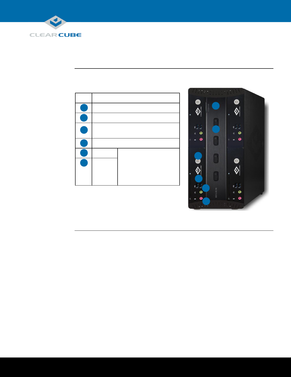
The picture below shows the front of a ClientCube 2 (depending on the model, product features might
differ slightly).
Description
1
Secure KVM switch or Secure KM switch
2
Port selectors
Zero client power button and session
indicators
4
USB ports
5
Audio out
Audio devices plugged into
zero clients are not switched.
Devices plugged into the
Console connectors on the
rear of the KVM or KM are
switched.
6
Audio in
Figure 1. ClientCube 2, front view
5
About ClientCube 2 with Secure KVM or Secure KM Switch,
Continued
Continued on next page
Page 2 of 14 P/N G0200161 Rev E, 1.4.08.27.2014
Page 3
ClearCube Technology, Inc. 3700 W Parmer Lane Austin, TX 78727 (512) 652-3500 www.clearcube.com
KVM cabling
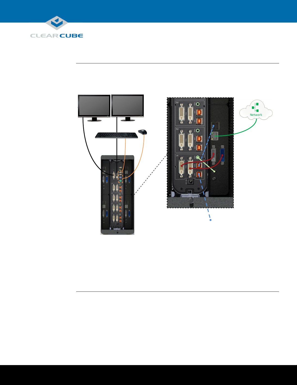
The picture below shows the default cabling configuration for ClientCube 2 with a KVM switch. For
simplicity, cabling is shown between the KVM and only one zero client. The same cabling
configuration is used for the remaining zero clients.
Figure 2. ClientCube 2 with KVM, rear view and default cabling configuration (for simplicity,
cabling for only one zero client is shown)
Optional External CAC Reader
KVM Switch in ClientCube 2
Cable Configuration
Page 3 of 14 P/N G0200161 Rev E, 1.4.08.27.2014
Page 4
ClearCube Technology, Inc. 3700 W Parmer Lane Austin, TX 78727 (512) 652-3500 www.clearcube.com
KM cabling
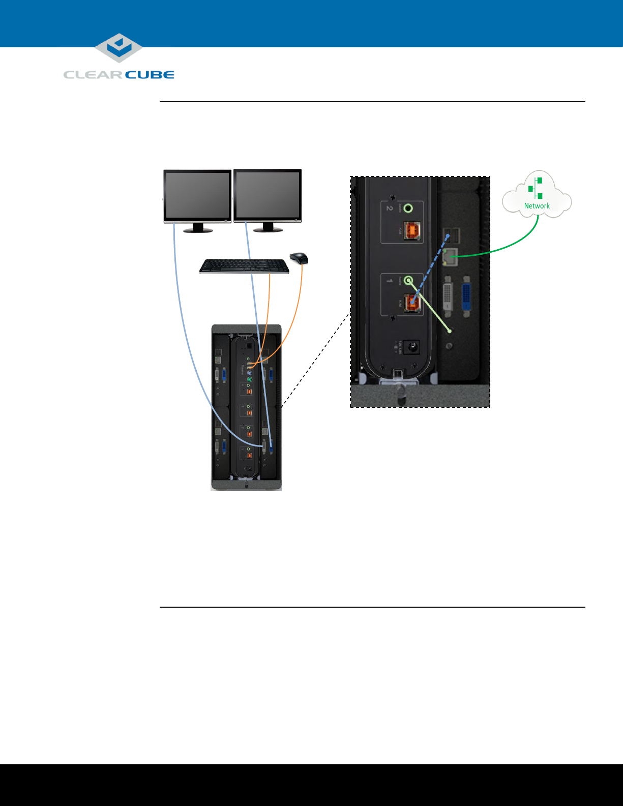
The picture below shows the default cabling configuration for ClientCube 2 with a KM switch. For
simplicity, cabling is shown between the KM and only one zero client. The same cabling
configuration is used for the remaining zero clients.
Figure 3. ClientCube 2 with KM, rear view and default cabling configuration (for simplicity,
cabling for only one zero client is shown)
KM Switch in ClientCube 2
Page 4 of 14 P/N G0200161 Rev E, 1.4.08.27.2014
Page 5
ClearCube Technology, Inc. 3700 W Parmer Lane Austin, TX 78727 (512) 652-3500 www.clearcube.com
Personal and
product safety
CAUTION:
Prevent ESD (electrostatic discharge) damage to ClientCube 2 and smart
card readers by always discharging your body and smart card before using
a reader (for example, by touching a grounded, unpainted, metal object).
ESD can vary depending on many environmental conditions, including
clothing that users wear and how they handle smart cards. ESD damage can
potentially cause unsupported card reader behavior including failure.
Always perform ESD prevention steps before using a card reader.
Inspect
packaging
If ClientCube 2 packaging or hardware (including holographic seals on the Secure KVM or KM)
shows any evidence of disruption, call ClearCube Support immediately at (800) 652-3400.
Not included in
package
Before installing a ClientCube 2, be sure to have
a network cable for each zero client, and
optionally, a network switch.
Before setup
The table below shows steps to take after unpacking a ClientCube 2.
Step
Action
1
Ensure all required infrastructure is in place and is configured. Depending on your
deployment, this can include
DHCP servers
a copper network (including switches, routers, and so on)
a fiber network (including media converters, switches, routers, and so on)
VMware® View infrastructure, and
CAC or smart card components and authentication/single-sign-on infrastructure
2
Record MAC addresses of zero clients and host cards for use during deployment and
configuration. (A configuration label on each ClearCube device specifies a MAC
address for the PCoIP device.)
3
If you are using physical computers with PCoIP host cards, download and install
audio and GPU drivers appropriate for your host card. ClearCube host cards only
support drivers available from ClearCube Support.
Before You Begin
Page 5 of 14 P/N G0200161 Rev E, 1.4.08.27.2014
Continued on next page
Page 6

ClearCube Technology, Inc. 3700 W Parmer Lane Austin, TX 78727 (512) 652-3500 www.clearcube.com
Before setup
(continued)
Step
Action
4
Optionally, install a CAC driver on any computing devices requiring CAC support.
5
If the ClientCube 2 includes a KM switch and you are connecting to computers with
multi-head displays, install the Belkin Advanced Secure KM Switch Mouse Filter
driver software (see www.clearcube.com/support).
CAUTION
Be sure to remove this driver from computers before using the
computer without the Secure KM. Failure to remove the driver
results in loss of mouse functionality when connected directly to
a computer.
Set up
ClientCube 2
and KVM
The table below shows how to set up ClientCube 2 with a KVM switch.
NOTE
:
Follow the steps in the order listed below—be sure to connect all video cables
before connecting power to ClientCube 2 (note that connecting power
automatically powers on ClientCube 2).
Step
Action
1
Connect Ethernet cables to ClientCube 2 zero clients.
2
Connect one or more displays to the Secure KVM Console Monitor Port(s).
3
Connect a keyboard and mouse to the Console portion of the Secure KVM.
4
Optionally, connect speakers and a CAC reader to the Console portion of the Secure
KVM.
5
Connect the ClientCube 2 power cable to a power outlet, and then connect the power
adapter to ClientCube 2.
Result: Secure KVM and zero clients power on.
Before You Begin, Continued
Setting up ClientCube 2 with KVM Switch
Continued on next page
Page 6 of 14 P/N G0200161 Rev E, 1.4.08.27.2014
Page 7

ClearCube Technology, Inc. 3700 W Parmer Lane Austin, TX 78727 (512) 652-3500 www.clearcube.com
Configure
devices and
connect
The table below shows how to configure zero clients and remote hosts, and how to connect.
Step
Action
1
Configure zero clients using the zero client on-screen display (OSD).
NOTE
For more information about the OSD and configuration, see the
appropriate zero client Quick Start Guide (included) and PC-over-IP
System User’s Guide (download from ClearCube Support).
2
If you are using physical devices with PCoIP host cards, use a Web browser to
configure the host card as appropriate for your environment. For more information,
see the documentation cited above.
3
From the zero client OSD, click Connect.
Result: If you are using direct connection or reserved DHCP addresses, you are
connected to the remote host specified during configuration. If you are using DHCP
and device discovery, a list of available hosts is displayed. Select a host to connect to.
Additional
steps
Optionally, install ClientCube 2 accessories including color chips to distinguish each port button,
and name labels to identify each network. See the included Secure DVI-I KVM User Manual for
more information.
Setting up ClientCube 2 with KVM Switch, Continued
Page 7 of 14 P/N G0200161 Rev E, 1.4.08.27.2014
Page 8

ClearCube Technology, Inc. 3700 W Parmer Lane Austin, TX 78727 (512) 652-3500 www.clearcube.com
Set up
ClientCube 2
and KM
The table below shows how to set up ClientCube 2 with a KM switch.
NOTE
:
Be sure that ALL components (monitors, remote computers, zero clients, and so
on) are powered OFF before performing any of the steps below. Follow the steps
in the order listed below (note that connecting power automatically powers on
ClientCube 2).
Step
Action
1
Be sure that all components (including monitors) are powered off as noted above.
2
Connect Ethernet cables to the zero clients in the rear of the ClientCube 2, and
connect the other end of the cables to the remote computers for each zero client
(through a network switch or by direct connection).
3
Connect one or more displays to the zero clients in the rear of the ClientCube 2 (see
step 5 in “Before setup” on page 6 about driver software for multi-head displays).
4
Connect a keyboard and mouse to the Console portion of the Secure KM.
5
Optionally, connect speakers to the Console portion of the Secure KM.
6
Power on all monitors (do not power on any other devices yet).
7
Connect the ClientCube 2 power cable to a power outlet, and then connect the power
adapter to ClientCube 2.
Result: Secure KM and zero clients power on.
See the section below for KM and monitor configuration information.
Configure KM
and monitors
The KM switch comes with many pre-defined monitor configurations and arrangements. You can also
create custom monitor arrangements. See the included Advanced Secure Keyboard/Mouse (KM)
Switch User Manual for detailed information about Seamless Cursor Switching (SCS), configuring
monitors, administrator mode, multi-head driver installation, and troubleshooting.
Additional
steps
Optionally, install ClientCube 2 accessories including color chips to distinguish each port button. See
Secure KM Switch User Manual for more information.
Setting up ClientCube 2 with KM Switch
Continued on next page
Page 8 of 14 P/N G0200161 Rev E, 1.4.08.27.2014
Page 9

ClearCube Technology, Inc. 3700 W Parmer Lane Austin, TX 78727 (512) 652-3500 www.clearcube.com
Using the
keyboard
Note that in many cases you can use the keyboard instead of the mouse when navigating the OSD and
when making connections to VMs. You can use the keyboard’s TAB key and arrow keys to move
focus on dialog box elements, and press the ENTER key to make selections. In many cases, this can
eliminate the need to use the mouse and toggle mouse modes as described below.
Mouse control:
OSD and VMs
When using zero clients with a Belkin Secure KM, special keyboard keystrokes are required to
control the connected mouse when zero clients are in a pre-session state (using the zero client on-
screen display [OSD] shown below) and before configuring VMs. The keystrokes toggle mouse
behavior modes for use on the zero client OSD and when configuring VMs for use with a KM. The
picture below shows the zero client OSD.
Figure 4. The zero client OSD
The list below shows the keystrokes that toggle mouse modes.
CTRL, CTRL, F11, b
This keystroke sets relative mode. Press this key combination when using the mouse to navigate
the OSD (and in VM sessions before configuration).
CTRL, CTRL, F11, c
This keystroke sets absolute mode. Press this key combination when using the OSD (and in VM
sessions before configuration) to enable Seamless Cursor Switching (to move from one monitor to
another). To re-gain control of mouse movements, press CTRL, CTRL, F11, b as described above.
NOTE
:
When connecting to VMs, zero clients must use TERA firmware 4.2.0. See
PCoIP Device and Firmware Compatibility Guide and PC-over-IP (PCoIP)
System User’s Guide for information about upgrading firmware.
Navigating OSDs and VMs
Page 9 of 14 P/N G0200161 Rev E, 1.4.08.27.2014
Page 10

ClearCube Technology, Inc. 3700 W Parmer Lane Austin, TX 78727 (512) 652-3500 www.clearcube.com
Dependencies
If you are connecting to physical devices (such as Blade PCs) with PCoIP host cards, use a Web
browser to configure the host card as appropriate for your environment. For more information about
Host Card configuration, see the appropriate zero client Quick Start Guide (included) and PC-over-IP
System User’s Guide (download from ClearCube Support).
Configure zero
clients and
connect
NOTE
This procedure requires switching mouse modes as described in “Mouse control:
OSD and VMs” above.
The table below shows how to connect to physical devices (such as Blade PCs).
Step
Action
1
From the keyboard, press CTRL, CTRL, F11, b to set the mouse to relative mode.
You can now use the mouse to configure the zero client or connect to a remote host.
NOTE
For information about the OSD and configuration options, see the
documentation cited in “Package contents and documentation” and
“For more information” on page 1.
2
From the zero client OSD, click Connect.
If you are using direct connection or reserved DHCP addresses, you are connected to
the remote host specified during configuration. If you are using DHCP and device
discovery, a list of available hosts is displayed. Select a host to connect to. You are now
connected to a remote host.
Connecting to Physical Devices
Page 10 of 14 P/N G0200161 Rev E, 1.4.08.27.2014
Page 11

ClearCube Technology, Inc. 3700 W Parmer Lane Austin, TX 78727 (512) 652-3500 www.clearcube.com
Overview
Interaction between a KM, zero clients, and VMware components requires setting options on the zero
client to bridge the USB keyboard and mouse to VMs. Set bridging options from the zero client Web
interface before connecting to VMs.
Find zero client
IP address
The table below shows how to find a zero client IP address. Use the zero client IP address to access
the device’s Web interface for additional configuration steps.
NOTE
This procedure requires switching mouse modes as described in “Mouse
control: OSD and VMs” above.
Step
Action
1
Press CTRL, CTRL, F11, b to set the mouse to relative mode.
2
From the zero client OSD in the upper-left portion of the screen, click Options >
Configuration. The Configuration screen shows the zero client’s IP address.
Record this IP address and click Cancel to close the screen.
3
Press CTRL, CTRL, F11, c to toggle to absolute mode and move the mouse to
the next zero client’s monitor(s).
4
Press CTRL, CTRL, F11, b to toggle to relative mode and record the zero
client’s IP address. Repeat this process for all zero clients in the ClientCube 2—
remember that you must toggle the mouse to absolute mode to move to the next
zero client.
Configure zero
client
The table below shows how to bridge the mouse and keyboard connected to the Secure KM.
Step
Action
1
From a Web browser, open a zero client’s Web interface by entering one of the
IP addresses you recorded in the previous procedure (you can safely dismiss any
security-related prompts that browsers display).
2
Click Log In (by default, a password is not required).
3
From the main menu, click Permissions > USB to display the USB page.
4
From the Bridged Devices section, click Add New.
5
Enter 050D in the Vendor ID text box and enter 104A in the Product ID text box.
Click Add. The bridged device IDs are now shown above the Add new button.
6
For deployments with daisy-chained KM and KVMs only: Clear the Enable
EHCI option.
Configuring Zero Clients for VM Connections
Continued on next page
Page 11 of 14 P/N G0200161 Rev E, 1.4.08.27.2014
Page 12

ClearCube Technology, Inc. 3700 W Parmer Lane Austin, TX 78727 (512) 652-3500 www.clearcube.com
Configure zero
client
(continued)
Step
Action
7
Click the Apply button located at the bottom of the screen. A success message is
displayed.
8
To restart the zero client, click Diagnostics > PCoIP Processor and then click
Reset. A message is displayed. Click OK.
This ends the PCoIP session with the zero client. Repeat this procedure for all
zero clients in the ClientCube 2.
Configuring Zero Clients for VM Connections, Continued
Page 12 of 14 P/N G0200161 Rev E, 1.4.08.27.2014
Page 13

ClearCube Technology, Inc. 3700 W Parmer Lane Austin, TX 78727 (512) 652-3500 www.clearcube.com
Dependencies
If you are connecting to VMs, these instructions assume you are using VMware products and have
your environment functioning and configured (including Domain users associated with VMs).
For more information about zero client configuration, see the appropriate zero client Quick Start
Guide (included) and PC-over-IP System User’s Guide (download from ClearCube Support).
Connect to VM
The table below shows how to connect to a VM from a zero client. These instructions assume you
have completed the steps shown in “Configuring Zero Clients for VM Connections” on page 11.
Step
Action
1
From a zero client OSD, press CTRL, CTRL, F11, b to ensure the mouse is in
relative mode. Click Connect. When the Certificate Warning is displayed, click
Continue.
2
Enter the user credentials and click Login.
3
Select a VM to connect to, and click Connect. The VM desktop is displayed.
The mouse is unable to perform Seamless Cursor Switching to switch from one
monitor (or computer) to the next. Press CTRL, CTRL, F11, c to switch the mouse
to absolute mode.
4
Move the mouse to the next monitor to switch to the next zero client in the ClientCube 2.
Once you are on the next zero client’s OSD, press CTRL, CTRL, F11, b to toggle to
relative mode so you can navigate the screen. Click Connect to connect to another VM
as shown in the previous steps.
5
Once connected to the desktop, press CTRL, CTRL, F11, c to toggle the mouse mode.
Seamless Cursor Switching (SCS) is now enabled and you can switch from zero client to
zero client by moving the mouse (see the included Secure KM Switch User Manual for
information about SCS). Repeat this process and connect to the remaining zero clients in
the ClientCube 2 and toggle the mouse mode by pressing CTRL, CTRL, F11, c to
enable Seamless Cursor Switching for all zero clients in the ClientCube 2.
Connecting to VMs
Page 13 of 14 P/N G0200161 Rev E, 1.4.08.27.2014
Page 14

ClearCube Technology, Inc. 3700 W Parmer Lane Austin, TX 78727 (512) 652-3500 www.clearcube.com
Documentation
resources
See “Package contents and documentation” and “For more information” on page 1 for a list of
documentation about ClientCube 2 components and concepts.
Contacting
Support
Web
UUUwww.clearcube.com/support/UUU
Email
UUUsupport@clearcube.com
Toll-free
(866) 652-3400
Direct
(512) 652-3400
Additional Information and Support
Page 14 of 14 P/N G0200161 Rev E, 1.4.08.27.2014
 Loading...