

Page 1

Quick Start Guide
USB Port
PCoIP Session
Indicator
Client Power &
Indicator
HD Audio In
Smart Card
Reader
Remote PC
Power
Front
HD Audio Out
Reader Activity
Indicator
DVI #2
USB Ports
SFP
Connector
Power Jack
HD Audio Out
DVI #1
Serial Number
MAC Address
Kensington Security Slot
Rear
Connection
Status
Indicators
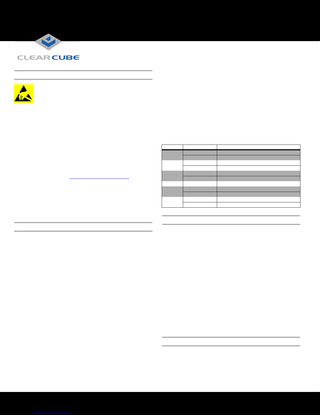
Rear
CD7424SFPST
Zero Client
Network
Copper
Chassis with Blades and VMs
Keyboard
Mouse
Displays
* Fiber
Infrastructure
* Media can vary depending on SFP module connected to zero client.
CD7424SFPST Zero Client
Zero Client Overview
ClearCube® CD7424SFPST Zero Clients connect to supported
ClearCube PC blades and virtual machines containing V5x20
Dual Host cards to provide the following:
• Small form-factor pluggable (SFP) socket, accepting various
Gigabit Ethernet modules
• Support for multi-mode, single-mode, and WDM single-mode
fiber media and for copper media
• Integrated smart card reader
• Support for up to two independently-configurable monitors
• PC–over–IP™ (PCoIP™) processors, delivering PC video and
audio over an IP network
• Three USB ports
• HD audio in (front) and HD 4.0 audio out
ClearCube PC blades are typically located in remote data centers.
Each blade user has a CD7424SFPST Zero Client on their desk, which
they use to connect to a remote blade or VM over an IP network
(consisting of fiber and Ethernet segments). Users connect monitors,
pointing devices, and other peripherals to their client, enabling them
to work on the blade or VM as if it is a local PC. The connection
between the zero client and the remote device is over PCoIP protocol.
Inside the blade, a V5x20 Dual Host card manages the PCoIP session.
ClearCube Technology 8834 Capital of Texas Hwy N Austin, Texas 78759 voice 512 652 3500 www.clearcube.com
Zero client connected to blade or VM with V5x20 host card
Ensuring Client & Host Firmware Compatibility
ClearCube PCoIP zero clients and host cards must use identical
firmware versions. If you are upgrading portions of existing
ClearCube deployments, ensure that all PCoIP devices use the same
firmware version. Additionally, devices must use firmware version
3.0 or higher in a VMware
Guide and PCoIP Firmware Support and Compatibility Guide on
the ClearCube Support site for instructions about identifying and
updating PCoIP device firmware.
®
View environment. See PCoIP User’s
—Continued on Reverse—
Page 2
Smart Card Reader Setup
Prevent ESD (electrostatic discharge) damage to smart
card readers by always discharging your body and
smart card before using a reader (for example, by
touching a grounded, unpainted, metal object). ESD
can vary depending on many environmental conditions,
including clothing that users wear and how they handle smart
cards. ESD damage can potentially cause unsupported card reader
behavior including failure. Always perform ESD prevention steps
before using the card reader.
Driver Requirement
To use the smart card reader, install a reader driver on the remote
device to which you connect and ensure that the card reader
service is running on the remote device. Download the driver to
install on devices from the CD7424SFPST Drivers section of
ClearCube Support site at www.clearcube.com/support
. The file
contains drivers for all supported operating systems and
installation instructions.
Pre-Session Authentication Firmware Requirement
TERA firmware revision 3.5.1 (or above) is required to support
pre-session authentication in your environment.
Buttons and Indicators
The list below shows indicators on the front panel and button operations:
front of the CD7424SFPST to put the remote PC in a soft off
(S5, hot) power state. Press the button again to wake the remote
PC. Video resumes at the OS login screen. You can change the
action performed when users press the Remote PC power
button. See the PCoIP User’s Guide for more information.
• Smart Card Reader
– Yellow-Green—smart card reader is powered on.
– Red—smart card has been reset. When red light is flashing,
the IC Card is reading or writing.
• Connection Status Indicators
LED State Meaning
PWR
LNKC
LNKF
FDX/COL Steady Full duplex connection
RX
TX
Steady Power on
Off No power
Steady TX port: network connection made (copper)
Off No connection
Steady RX port: network connection made (fiber)
Off No connection
Steady Receiving data
Off No reception
Steady Transmitting data
Off No transmission
Mandatory Setup & Cooling Requirements
• Ensure at least 4 inches of space around all zero client edges
and at least 2 inches of space above the client.
• Power Button Colors
– Green (solid): CD7424SFPST is powered on.
– Green (blinking): PCoIP session is sleeping. Press any key
on the keyboard to wake the session.
– Orange: CD7424SFPST is powered off.
• Power Button Operations
– Power on: when orange, press briefly (button turns green)
– Disconnect session: when green, briefly press (button
blinks green)
– Power off: press and hold for 3 seconds (button turns orange)
• PCoIP Session Indicator—shows when a connection, or
session, is established between the CD7424SFPST and a blade.
The link indicator displays one of the following:
– Green—a session is established between the client and a blade.
– Off—there is no session between the client and a blade.
• Remote PC Power—when an CD7424SFPST is connected to
a remote PC host, you can press the Remote PC button on the
• Ambient temperature around a client must not exceed 35° C (95° F).
• Do not stack any objects on top of the zero client.
• Do not block the zero client’s side vents by leaning papers,
folders, computer speakers, or any other objects against the
sides of the client.
• Adjacent furniture (file drawers, desk supports, chairs) do not
block or enclose any sides of the zero client.
• Ensure that the zero client is standing vertically.
• Do not place the zero client in enclosed environments such as
on a shelf or inside a drawer.
• Ensure that cables connected to the zero client are supported.
Setting up the CD7424SFPST Zero Client
Perform the following steps to connect peripherals and a network
cable to the zero client.
MOUNTING & COOLING REQUIREMENTS DETAILED BELOW.
FAILURE TO DO SO CAN DAMAGE THE ZERO CLIENT.
ENSURE YOU FOLLOW THE
—Continued—
ClearCube Technology 8834 Capital of Texas Hwy N Austin, Texas 78759 voice 512 652 3500 www.clearcube.com
G0200150 Rev A
Page 3

1. Connect a USB keyboard and a mouse to the USB ports on the
front or on the rear of the zero client.
2. Connect an appropriate network cable to the SFP module
located on the rear of the zero client, and then connect the other
end of the cable to the appropriate network infrastructure
device (such as a fiber network switch or a fiber transceiver).
NOTE:
The zero client is set to forced full-duplex mode with
flow control (Link Fault Passthrough) disabled.
These settings should be the same on any network
switch to which the zero client connects. Check
your switch settings and make any necessary
changes (see “Network Settings” below for
information about configuring Cisco switches).
3. Connect a monitor cable to each DVI-I port on the rear of the
zero client. If you are using VGA monitors, attach DVI
adapters to your monitor cables.
4. Connect the AC power adapter to the power cable (both are
included with the zero client).
5. Connect the power adapter to the rear of the client, and then
plug the power cable into a power outlet. See “Buttons and
Indicators” for information about powering the zero client on
and off.
NOTE: You can enable a zero client to receive an IP address from
a DHCP server. If a DHCP server does not assign an
address within a designated timeout period, the zero client
uses a default, fallback IP address. If you use these default
addresses and have DHCP enabled, you must wait 120
seconds before you can connect to a host. If you use the
direct connect methodology in your environment,
ClearCube recommends disabling the client's DHCP
setting to eliminate the need to wait 120 seconds before
connecting. See PCoIP System User’s Guide at
www.clearcube.com/support
for more information.
See “Configuration Steps and Additional Information” for more
information.
Network Settings
The CD7424SFPST zero client is set to:
• Forced, full-duplex mode, 1000 Mbps
• Flow control (Link Fault Passthrough) disabled
These settings should be the same on any network switch to which
the zero client connects. Check your switch settings and make any
necessary changes.
The following example shows how to configure negotiation and
flow control settings on Cisco Catalyst
®
switches to connect with
CD7424SFPST zero clients (note that these commands are not
applicable to Cisco Nexus
router# configure terminal
router(config)# interface gigabitethernet 0/1
router(config-if)# no negotiation auto
router(config-if)# flowcontrol send off
router(config-if)# flowcontrol receive off
router(config-if)# end
router#
®
switches).
If you use different switches in your environment, perform
equivalent commands to disable auto-negotiation and flow control.
Configuration Steps and Additional Information
See PC-over-IP System User’s Guide and PCoIP Firmware Support
and Compatibility Guide at
information about zero client deployment, configuration, and
administration. If you are using ClearCube Sentral in your
environment, see Sentral Administrator’s Guide for information
about connection brokering, device administration, and more.
Web sit e : www.clearcube.com/support
Email: support@clearcube.com
Toll-free: (866) 652-3400
Phone: (512) 652-3400
www.clearcube.com/support
for
WEEE Disposal Guidelines
In the European Union, this electronic product is under European Directive (2002/96/EC) WEEE. When this product reaches the end of its useful life or is
no longer used, do not discard it with conventional waste. Recycle this product at an approved, designated recycling or treatment facility. Check with local
authorities for proper disposal instructions. For assistance, contact recycle@clearcube.com
ClearCube Technology 8834 Capital of Texas Hwy N Austin, Texas 78759 voice 512 652 3500 www.clearcube.com
G0200150 Rev A
 Loading...