

Page 1
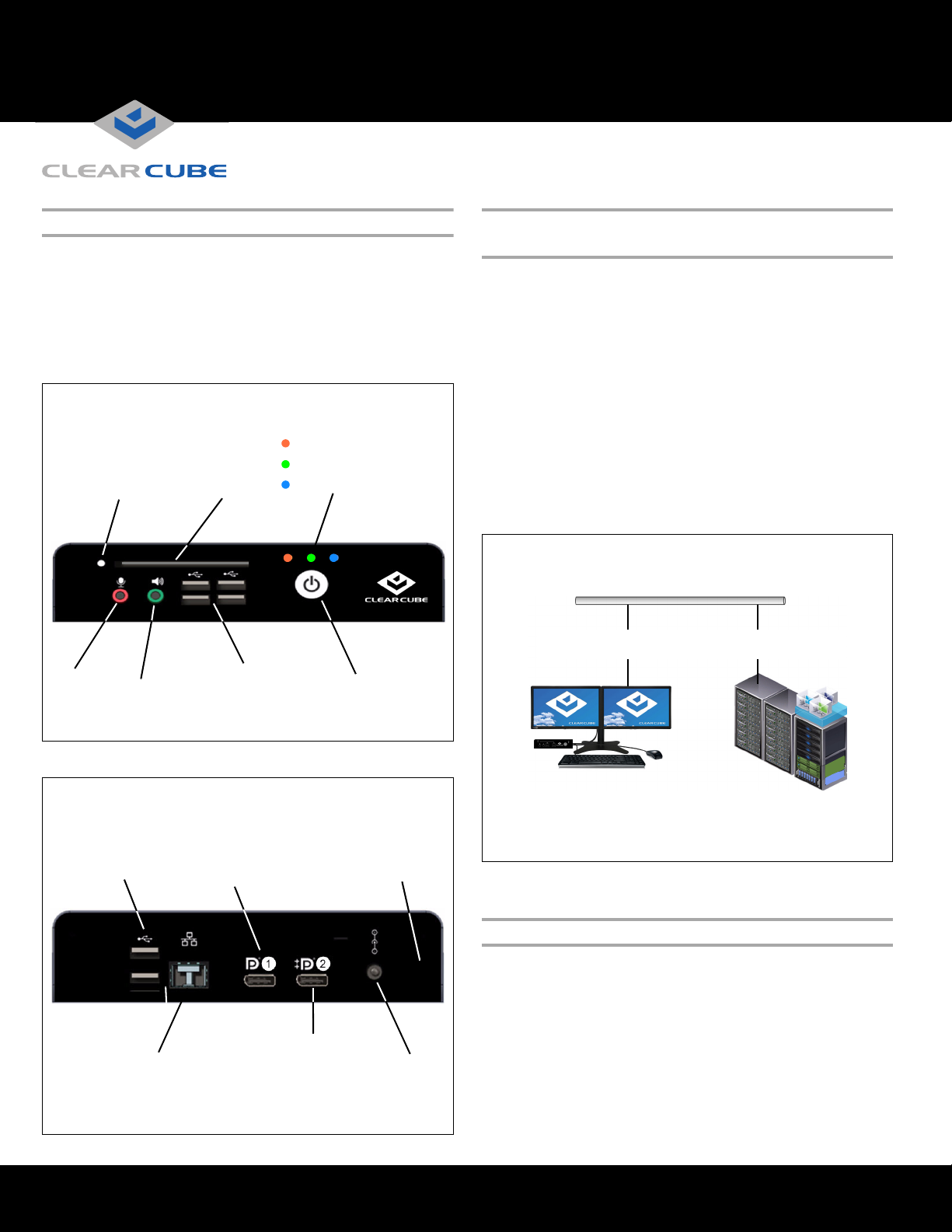
USB Ports
(× 4)
Power Button
Front
Smart Card Reader
Activity Indicator
Indicators:
Standby Power
Power On
PCoIP Session Established
HD
Audio In HD
Audio Out
Smart Card
Reader
(
Models CD1024 and CD2024 Only)
DisplayPort
Connector
USB
Ports
(× 2)
Ethernet Connector
(RJ45: CD2020-Series
SFP: CD1020-Series)
Power
Jack
MAC Address
and Serial Number
Rear
DisplayPort++
(Dual-Mode)
Connector
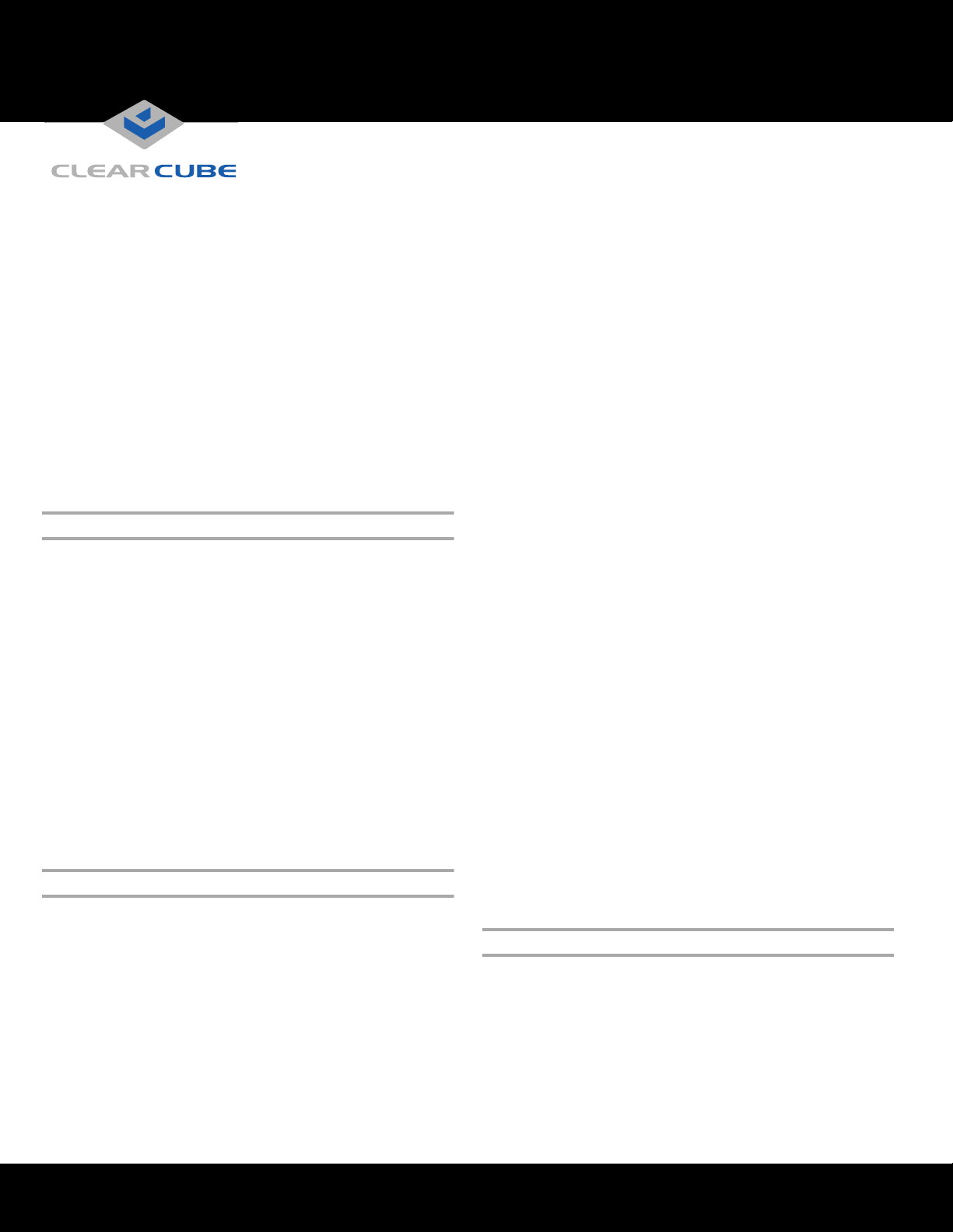
Cloud Desktop with Monitors
and Peripherals
Network Infrastructure
Chassis with
Blades and VMs
Copper and Fiber Ethernet
(Network Media Varies by Model)
CD1020-Series, CD2020-Series
Cloud Desktop Quick Start Guide
Package Contents CD1020-series, CD2020-series
Cloud Desktop Overview
• CD1020-series or CD2020-series Cloud Desktop
• Power adapter and cable
•This Quick Start Guide
(NOTE: the terms Cloud Desktop and zero client are used
interchangeably in this document.)
A Cloud Desktop, or zero client, is a remote computing
device that connects a user’s monitors, keyboard, mouse,
speakers, and other peripherals to remote ClearCube Blade
PCs (computers) and to virtual desktops (VMs). As shown
below, computing resources are typically located in remote
data centers. Cloud Desktops enable users to work on a blade
or VM as if it is a local PC. The connection between the zero
client and the remote device is over PCoIP
the remote device, a host card manages the PCoIP session.
®
protocol. Inside
ClearCube Technology, Inc. 3700 W Parmer Lane Austin, Texas 78727 (512) 652-3500 www.clearcube.com
Cloud Desktop connected to blade or to VM
Cloud Desktop Features
ClearCube® CD1020-series and CD2020-series zero clients
connect to supported ClearCube Blade PCs containing
Tera1 or Tera2 host cards and to virtual machines to provide:
•Six USB ports
• Support for fiber Ethernet media (model CD102x) or
copper Ethernet media (model CD202x)
Page 2
Page 2 of 4
• Support for independently-configurable monitors:
– 1 monitor at 2560 × 1600 (using a single cable)
– 2 monitors at 1920 × 1200 (using two cables)
DP++ (Dual-mode) connector (Port 2) supports DVI
using a passive DisplayPort-to-DVI cable (not provided)
• Tera2 processors, delivering PC video, audio, and USB
over an IP network
• Integrated smart card reader (CD1024 and CD2024 only)
• HD audio in and out
Client and Host Firmware Compatibility
Always use compatible Teradici® firmware versions on
connected PCoIP devices.
• CD1020-Series and CD2020-Series zero clients
include Tera2 processors, requiring Teradici firmware
4.0.3 and higher.
• Be sure that any Tera1 devices (zero client models lower
than CD9600-series and CD7600-series and any host
card models lower than V5400-series) in a deployment
use the device’s Tera1-specific firmware.
– When the PCoIP session indicator is illuminated (blue):
• If connected to a PCoIP host card, press to display
the Zero Client Control Panel (on monitor) with
options to disconnect or power down the remote
host device. Press the power button repeatedly to
scroll through the options or to cancel.
• If connected to a VM, press to disconnect.
• Power Indicator
– Green (solid): device is powered on.
– Green (blinking): PCoIP session is sleeping. Press
any key on the keyboard to wake the session.
• Standby Indicator: device is in low-power state and
wake-on-LAN (WoL) or wake-on-USB (WoUSB) is
®
enabled. ClearCube Sentral
or third-party utilities can
provide WoL and WoUSB features.
• PCoIP Session Indicator—shows when a connection, or
session, is established between the zero client and a host.
The link indicator displays one of the following:
– Blue—a session is established between the client and
a host.
– Off—there is no session between the client and a host.
See PCoIP Firmware Support and Compatibility Guide on
• Smart Card Reader (on supporting models only)
the ClearCube Support site for instructions about identifying
and updating PCoIP device firmware.
– Yellow-Green—smart card reader is powered on.
– Red—smart card has been reset. When red light is
Buttons and Indicators
flashing, the IC Card is reading or writing.
The list below shows indicators and front panel button
operations (see figure on previous page for locations):
• Power Button Operations
USB Ports and Power
CD1020- and CD2020-Series zero clients provide six USB
ports (three dual-stack pairs). For full power USB (1 Amp),
– To po wer on : when the standby indicator is orange,
press the button briefly to power on the zero client.
The power indicator turns green.
connect a device to one of the ports in a pair, and leave the
other port in the paired stack empty. Use this feature to
support USB peripherals requiring higher power, or to
charge USB devices faster.
– To power off: When the power indicator is green,
press and hold for 3 seconds. The standby indicator
turns orange.
ClearCube Technology, Inc. 3700 W Parmer Lane Austin, Texas 78727 (512) 652-3500 www.clearcube.com
G0200178 Rev A, 1.0.03.01.2016
Page 3

Page 3 of 4
Mandatory Setup and Cooling Requirements
• Ensure at least 4 inches of space around zero client edges
and at least 2 inches of space above the zero client.
• Ambient operating temperature: 0° to 35° C
(32° to 95° F).
• Do not stack any objects on top of the zero client.
• Do not block the zero client’s side vents by leaning
papers, folders, computer speakers, or any other objects
against the sides of the client.
• Adjacent furniture (file drawers, desk supports, chairs) do
not block or enclose any sides of the zero client.
• Do not place the zero client in enclosed environments
such as on a shelf or inside a drawer.
• Ensure that all connected cables are supported.
Default Settings and Fallback IP Address
•DHCP enabled
• SLP discovery enabled
Smart Card Reader Setup (on Supporting Models)
Prevent ESD (electrostatic discharge) damage to
smart card readers by always discharging your
body and smart card before using a reader (for
example, by touching a grounded, unpainted,
metal object). ESD can vary depending on many
environmental conditions, including clothing that users wear
and how users handle smart cards. ESD damage can
potentially cause unsupported card reader behavior
including failure. Always perform ESD prevention steps
before using the card reader.
CD1024 and CD2024 zero clients include a PKI-approved
CAC/SIPRnet smart card reader that supports 5V, 3V, and
1.8V smart cards.
To use the smart card reader, you must install a driver for
the reader on the blade to which you connect and ensure that
the card reader service is running on the blade. Download
the driver to install on blades from the blade’s Drivers
section of ClearCube Support site. The download file
contains drivers for all supported operating systems and
installation instructions.
• Session type: direct to host + SLP discovery
• Fallback IP addresses:
– Zero client: 192.168.1.100
– Host card: 192.168.1.101
By default, zero clients and host cards are configured to
receive an IP address from a DHCP server. If a DHCP
server does not assign an address within a designated
timeout period (120 seconds), the zero client uses a default,
fallback IP address. Fallback addresses enable devices to
always have a known IP address. See PC-over-IP System
User’s Guide for more information.
NOTE: If you use the fallback addresses and have DHCP
enabled, you must wait 120 seconds before you can
connect to a host. If you use the direct connect
methodology in your environment, ClearCube
recommends disabling the client's DHCP setting to
eliminate the need to wait 120 seconds before
connecting. See PC-over-IP System User’s Guide at
www.clearcube.com/support
for more information.
Setting up a Cloud Desktop
Perform the following steps to connect peripherals, a
network cable, and a power supply to the zero client. These
steps assume that the Cloud Desktop, host card, and DHCP
server are on the same network.
NOTE: When connecting to physical devices using a single
monitor or any number of monitors at 2560 × 1600
resolution, install Teradici PCoIP Host Software on the
physical device. (This requirement does not apply to
VMs.) Teradici PCoIP Host Software is available from
Teradici Support. (Note that ClearCube factory images
include Teradici PCoIP Host Software by default).
Ensure that the host driver function on the peer host card
is enabled (it is enabled by default). See Tech Bulletin
TB00274: Configuring Dual-Monitor Systems for SingleMonitor Use on ClearCube Support for information.
1. Power on the remote Blade PC containing the host card to
which you are going to connect.
ClearCube Technology, Inc. 3700 W Parmer Lane Austin, Texas 78727 (512) 652-3500 www.clearcube.com
G0200178 Rev A, 1.0.03.01.2016
Page 4

Page 4 of 4
2. Connect one or more monitors to the zero client (clients
do not currently support daisy-chaining displays).
3. Connect a network cable to the connector located on the
rear of the zero client (fiber or copper, depending on
model), and then connect the other end of the cable to the
appropriate network infrastructure device (such as a
network switch, fiber transceiver, or router).
4. Connect a USB keyboard and a mouse to the USB ports
on the front or on the rear of the zero client.
5. Connect the AC power adapter to the power cable
(included with the zero client).
6. Connect the power adapter to the rear of the client, and
then plug the power cable into a power outlet. Ensure that
the zero client and the host card are on the same network.
See “Buttons and Indicators” for information about
powering the zero client on and off.
You can now click Connect and select the host card to
connect to from the list displayed on the OSD.
Configuration Steps and Additional Information
See PC-over-IP System User’s Guide and PCoIP Firmware
Support and Compatibility Guide at www.clearcube.com
information about zero client deployment, configuration,
and administration. If you are using ClearCube Sentral in
your environment, see Sentral Administrator’s Guide for
information about connection brokering, device
administration, and more.
Web site: www.clearcube.com/support
Email: support@clearcube.com
Toll-free: (866) 652-3400
Phone: (512) 652-3400
for
Trademarks
ClearCube, Sentral, SmartVDI, Blade Switching BackPack, C/Port, and I/Port are trademarks or registered trademarks of ClearCube Technology, Inc.
PC-over-IP and PCoIP are registered trademarks of Teradici Corporation in the United States and/or other countries.
Kensington is a registered trademark of ACCO Brands.
WEEE Disposal Guidelines
In the European Union, this electronic product is under European Directive (2002/96/EC) WEEE. When
this product reaches the end of its useful life or is no longer used, do not discard it with conventional
waste. Recycle this product at an approved, designated recycling or treatment facility. Check with local
authorities for proper disposal instructions. For assistance, contact
ClearCube Technology, Inc. 3700 W Parmer Lane Austin, Texas 78727 (512) 652-3500 www.clearcube.com
recycle@clearcube.com
.
G0200178 Rev A, 1.0.03.01.2016
 Loading...