

Page 1
ClearCube Technology, Inc. 3700 W Parmer Lane Austin, TX 78727 (512) 652-3500 www.clearcube.com
A6106HL
components
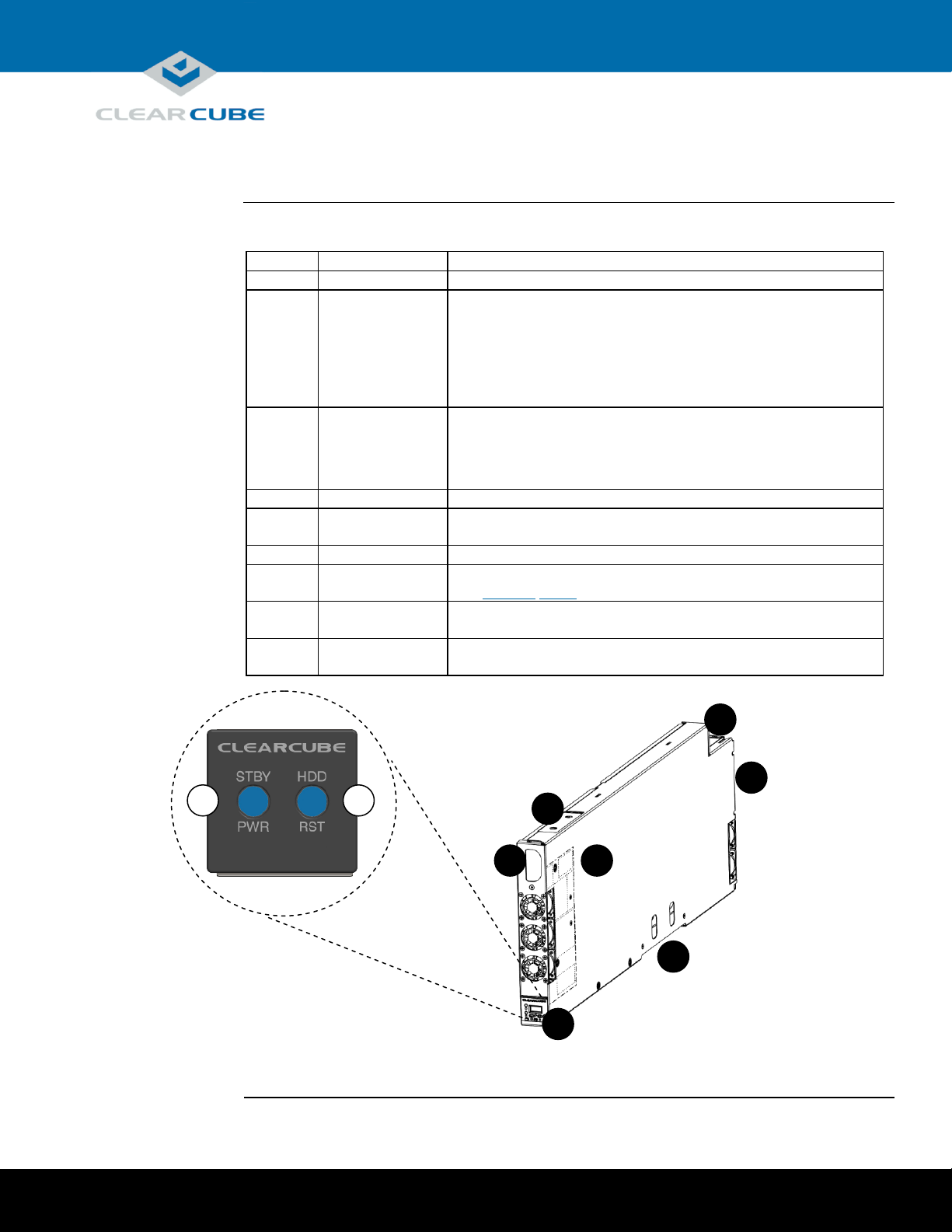
The table and picture below show each A6106HL Blade PC component.
Number
Part
Function
1
Front panel
Provides indicators and power-related buttons.
1A
Power button
and indicator
Button:
Press to power on and power off blade. Press and hold for 3 seconds
to force power off. Button is illuminated (solid) when power is on.
Indicator:
Power button flashes slowly when blade is in standby (Windows
Sleep power state).
1B
Reset button and
HDD indicator
Button:
Press to reset blade power.
Indicator:
Button flashes to indicate hard drive activity.
2
Handle
Use to aid insertion and removal from chassis.
3
I/O access slot
Provides access to select motherboard I/O ports for configuration
outside of the A-series chassis.
4
Power connector
Connects to A-series chassis AC power supply.
5
Ethernet ports
Connect to Ethernet ports on the A-series chassis backplane.
See Figure 5 below for details about backpack connections.
6
Storage drive
carrier
Holds up to two storage drives, connecting directly to SATA
connectors inside the blade. Does not support hot-swap operation.
7
Video
configuration label
Provides important blade configuration information, including
video host card MAC address, serial number, and more.
Figure 1. The A6106HL Blade PC components
1A
1B
1
3
4
5
6
2
7
A6106HL Blade PC Quick Start Guide
Page 1 of 11 P/N G0200172 Rev A, 1.0.03.14.2016
Page 2
ClearCube Technology, Inc. 3700 W Parmer Lane Austin, TX 78727 (512) 652-3500 www.clearcube.com
About this
guide
This quick start guide shows the components and features of A6106HL Blade PCs; how to
install and remove blades from an A-series chassis; how to view pre-OS video; how to
implement Intel® AMT; and provides references to additional information about A-series
blades, A-series chassis, and to information about using PCoIP® technology.
A6106HL
overview
A6106HL blades are 6U high, single-slot blades that mount in an A3100 chassis. The A3100
chassis provides power, network interfaces, and USB ports for each blade.
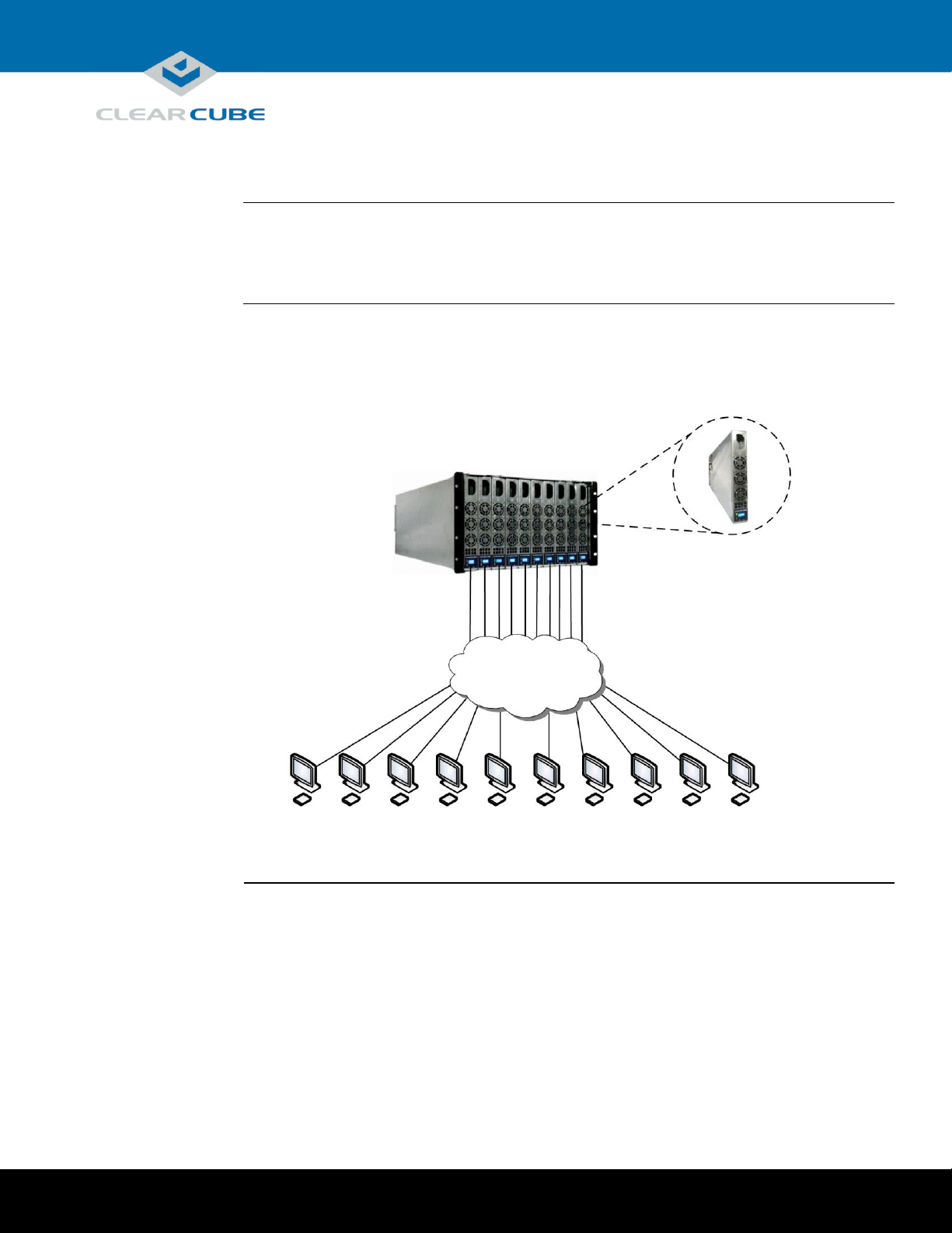
The picture below shows zero clients connected to A6106HL blades in an A3100 chassis.
Figure 2. An example deployment of A6106HL blades and zero clients
A3100 Chassis
A6106HL Blade
WAN/LAN
Zero Clients
Introduction
Page 2 of 11 P/N G0200172 Rev A, 1.0.03.14.2016
Page 3
ClearCube Technology, Inc. 3700 W Parmer Lane Austin, TX 78727 (512) 652-3500 www.clearcube.com
Power on and
power off
The power button is located on the left portion of the front panel, shown as 1A in Figure 1 on page 1.
Power on: After inserting a blade in a chassis or connecting power for configuration outside of a
chassis, press the power button to power on the blade.
Result: The blade powers on and the power indicator (1A) is illuminated.
Power off: Press and hold the power button for about 3 seconds to power off a blade.
Result: The blade powers off and the power indicator (1A) turns off.
Reset power
The reset button is located on the right portion of the front panel, shown as 1B in Figure 1 on page 1.
When a blade is powered on, press the reset button to reset power.
Result: The blade powers down, the power indicator (1A) turns off, and the blade powers on again.
About blade
storage drives
A6106HL blades use a carrier to mount storage drives—such as hard disk drives (HDD), solid state
drives (SSD), self-encrypting drives (SED), and hybrid drives (SSHD).
NOTE:
A6016HL blades do not support hot-swap replacement of drives. When configuring an
A6106HL blade outside of a chassis, be sure to power down the blade and remove the
power cable before removing drives or servicing any components.
Storage drives do not require power cables or data cables when mounted in the storage drive carrier. Power
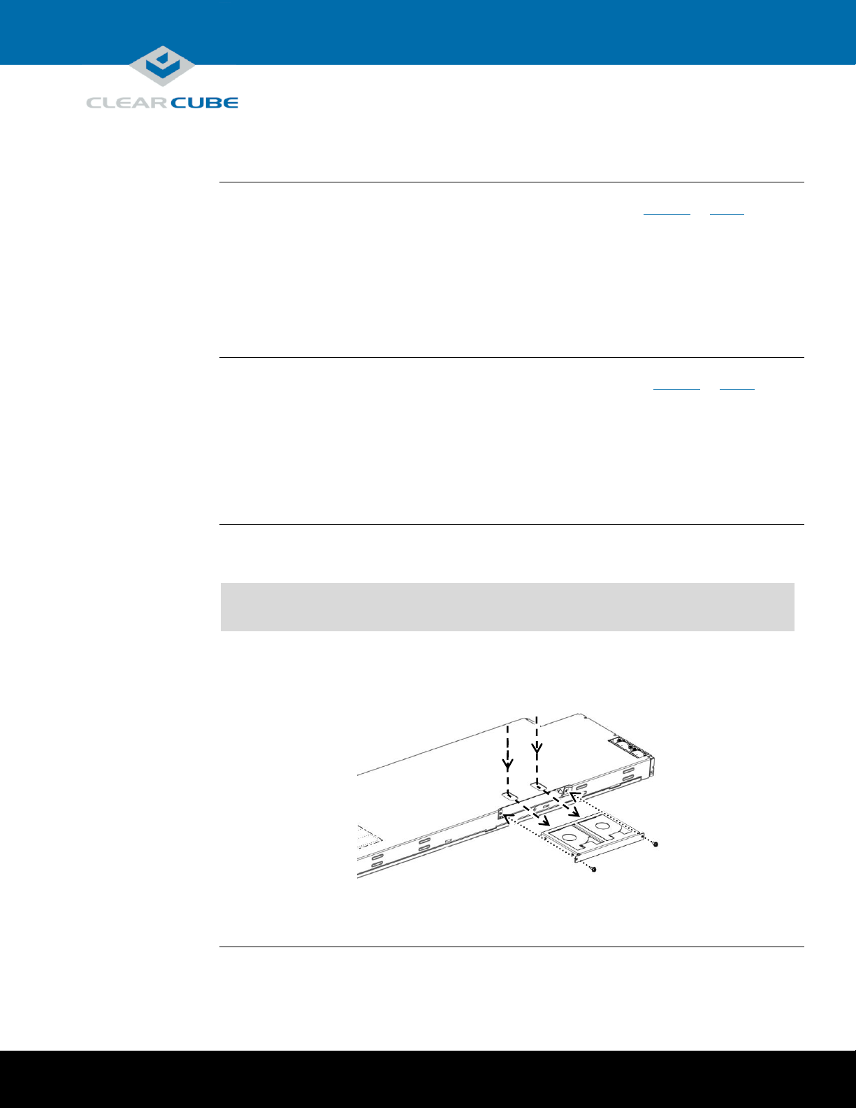
and data connectors are housed inside the blade—insert and fully seat the carrier and fasten with screws.
The picture below shows the storage drive carrier.
Figure 3. Removing and attaching the storage drive carrier
Storage Drive Carrier
Mounting Screws
Finger Holes for Carrier Removal
Power management
Storage drives and carrier
Continued on next page
Page 3 of 11 P/N G0200172 Rev A, 1.0.03.14.2016
Page 4
ClearCube Technology, Inc. 3700 W Parmer Lane Austin, TX 78727 (512) 652-3500 www.clearcube.com
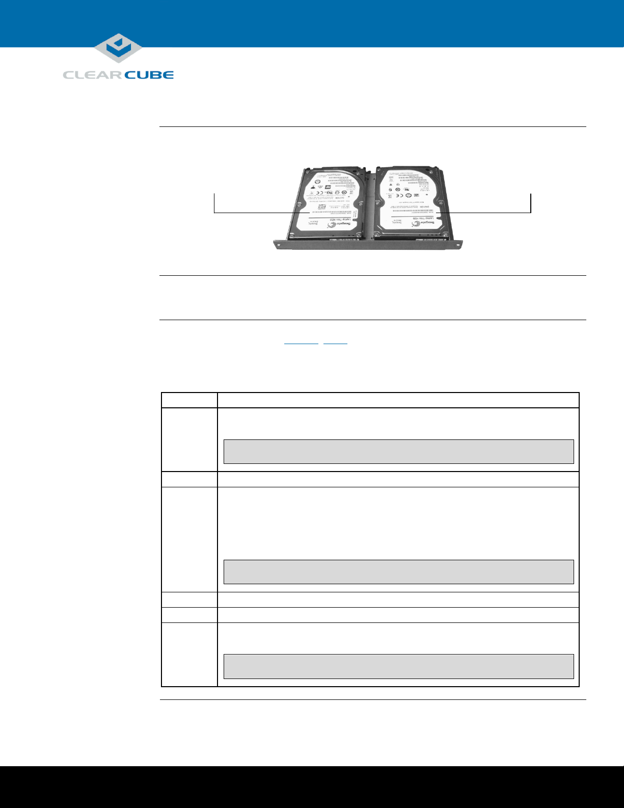
Drive order
The picture below shows how storage drives are numbered in the storage drive carrier.
Figure 4. Drive order in the storage drive carrier
Inserting and
removing
The A3100 chassis (shown in Figure 2, above) provides redundant power, network ports (Ethernet
and dedicated PCoIP), and USB ports for all blades in a chassis.
The table below shows how to install and remove an A6106HL blade from an A3100 chassis.
Step
Action
1
Open the chassis front bezel by pressing in on the latch on the upper-right side of
the chassis.
NOTE:
When pressing the latch to open the front bezel, hold the bezel with
one hand to ensure that the bezel does not fall.
2
From the top, pull the bezel toward you and lift up to remove it.
3
Hold the blade so the D-shaped handle in the front of the blade is upright and is
facing you. Align the blade with the top and bottom guides in the chassis and
slowly insert the blade.
Result: When fully seated, the blade is flush with the front edge of the bottom
guide bracket.
NOTE:
There is slight resistance when blade connectors are inserted into
backplane connectors.
4
Replace the bezel after inserting your blades.
5
Optionally, press the power button on the front panel to power on the blade.
6
To remove a blade, pull gently on the D-shaped handle until the blade slides out of
the chassis.
NOTE:
Support both ends of the blade when you remove it completely from
the chassis. Remember to replace the chassis front bezel.
Drive 0
Drive 1
Storage drives and carrier, Continued
Installation in A3100 chassis
Continued on next page
Page 4 of 11 P/N G0200172 Rev A, 1.0.03.14.2016
Page 5

ClearCube Technology, Inc. 3700 W Parmer Lane Austin, TX 78727 (512) 652-3500 www.clearcube.com
Additional
steps
The list below shows some additional deployment and setup steps you can take.
Insert Ethernet cables in the active port or ports, located on the rear of the chassis, for each blade
in the chassis (active ports are indicated by illuminated LEDs).
Install an operating system image appropriate for your environment.
NOTE:
Custom images for ClearCube blades have specific requirements. Be
sure to see the technical bulletin specified below for more information.
Set mass storage lockout, which enables you to prohibit and restrict the use of USB-based mass
storage devices (such as flash drives) on ClearCube blades.
A3100 chassis
Expansion
Backplane
As noted above, the A3100 chassis provides power and network connections for A6106HL blades.
The picture below shows the A3100 Expansion Backplane, located on the rear of the chassis, which
provides network connections.
Chassis ports
and protocol
assignment
Network ports on the rear of the A3100 chassis support different features. The picture below shows
the rear of the chassis and shows protocol support for each port.
Figure 5. The A3100 chassis and Expansion Backplane
Intel AMT Support
(from Primary Ethernet Port)
and Standard Ethernet
Dedicated PCoIP Port
A3100 Chassis and
Expansion Backplane
Standard Ethernet
Installation in A3100 chassis, Continued
A3100 Chassis Ports and Protocol Support
Page 5 of 11 P/N G0200172 Rev A, 1.0.03.14.2016
Page 6

ClearCube Technology, Inc. 3700 W Parmer Lane Austin, TX 78727 (512) 652-3500 www.clearcube.com
About pre-OS
video
In the A-series architecture, host cards with PCoIP technology do not support local video at the blade,
and USB is redirected to the zero client after the operating system starts.
To access A6106HL pre-OS video (such as BIOS setup utility screens), remove the blade from the
chassis and use a zero client to view pre-OS video.
Alternatively, you can use Intel® Active Management Technology (Intel® AMT) to view BIOS
screens after configuring Intel AMT on the blade (see “Using Intel® Active Management Technology
(Intel® AMT)” below).
Before you
begin
These sections assume that you are configuring an A6106HL blade outside of a chassis.
Before you begin, be sure to have
Ethernet cables
a standard 120 V computer power cable (IEC 60320 C13 connector with NEMA 5-15 inlet)
a zero client power supply
a ClearCube zero client compatible with the blade’s video configuration (a dual zero client for a
dual host card or a quad zero client for a quad host card). The blade’s video configuration is
specified on a label on the side of the blade (shown as item 7 in Figure 1 on page 1).
two or four DVI monitors (depending on zero client) and power cables
a USB keyboard and a mouse, and
a switch connected to a DHCP network.
NOTE:
These instructions assume devices are connected to an imaging network or
other network with a DHCP server to provide IP addresses for the blade’s
PCoIP host card and for the zero client. MAC addresses are specified on
labels on the side of the blade and on the zero client. To identify the host
card to connect to from the zero client, you might need to consult DHCP
tables. DHCP tables should show each device’s MAC address and the
corresponding IP address assigned to the host card and the client.
Connecting
devices
The table below shows how to connect devices to view pre-OS video.
Step
Action
1
Remove the blade from the chassis as described in “Inserting and removing” on
page 4. Place the blade on a stable surface, such as a bench or on the top of a desk.
2
Connect a USB keyboard to a port on the top of the blade. (Ensure that you do not
disconnect any Ethernet cables that might be visible from this opening.)
NOTE:
Connect a monitor to a zero client as described below. Do not connect
a monitor to a DVI port or to a DisplayPort™ on the top of the blade.
BIOS and pre-OS video for configuration and imaging
Page 6 of 11 P/N G0200172 Rev A, 1.0.03.14.2016
Continued on next page
Page 7

ClearCube Technology, Inc. 3700 W Parmer Lane Austin, TX 78727 (512) 652-3500 www.clearcube.com
Connecting
devices
(continued)
Step
Action
3
Connect the blade and the zero client to your network.
Step
Action
1
Connect an Ethernet cable to the blade’s dedicated PCoIP port (this is
the top-most port when the blade is resting on a table as shown below).
Connect the other end of the cable to a switch connected to your network.
Figure 6. Ports on the rear of the blade
2
Connect the zero client to the same switch.
3
Optionally, if you are imaging the blade, connect an Ethernet cable to the
standard Ethernet port on the rear of the blade (this is the bottom-most
port when the blade is resting on a table as shown above), and connect
the other end of the cable to the switch.
4
Connect monitors to the zero client (two or four depending on the zero client).
Connect a mouse to the zero client.
5
Connect a power cable to the power connector at the rear of the blade and then plug
the cable into a power outlet. Continue by connecting the zero client power adapter
to the client and then plugging the cord into a power outlet.
Next steps: power on devices, create a PCoIP session, and view pre-OS video.
Dedicated PCoIP
Standard Ethernet
BIOS and pre-OS video for configuration and imaging, Continued
Continued on next page
Page 7 of 11 P/N G0200172 Rev A, 1.0.03.14.2016
Page 8

ClearCube Technology, Inc. 3700 W Parmer Lane Austin, TX 78727 (512) 652-3500 www.clearcube.com
Create session
and view video
The table below shows how to create a PCoIP session to view pre-OS video.
Step
Action
1
Press the power button on the front of the blade to power it on, and then press the
power button on the front of the zero client to power it on.
2
From a monitor connected to the zero client, click the Connect button.
Result: After several moments the zero client identifies host cards to which it can
connect. The zero client on-screen display (OSD) lists one or more host card IP
addresses and their corresponding MAC addresses.
NOTE:
The video host card MAC address is specified on a label on the side of
the blade.
3
Select the blade’s host card from the list and click OK.
Result: The zero client and blade establish a PCoIP session displaying the blade’s
desktop.
4
Reset blade power from the operating system Start menu or by pressing the reset
button on the front of the blade. Watch monitors for pre-OS video (for example, a
message to press the F2 key for configuration screens) and press the appropriate key.
5
After performing configuration steps, power off both devices. Remove the blade and
zero client power cables from the power outlets and then remove the cables from
each device.
6
Remove all peripherals from both devices.
7
Replace the blade in the chassis as described previously.
Next steps: You can now deploy the A6106HL blade. See the documentation shown below for
important details about A6106HL configuration, operation, and maintenance.
BIOS and pre-OS video for configuration and imaging, Continued
Continued on next page
Page 8 of 11 P/N G0200172 Rev A, 1.0.03.14.2016
Page 9

ClearCube Technology, Inc. 3700 W Parmer Lane Austin, TX 78727 (512) 652-3500 www.clearcube.com
About Intel
AMT
Intel AMT enables administrators to manage supported blades remotely (including when blades are
powered off) using an AMT management console.
A6106HL blades support Release 9.0 and above.
Requirements
The table below details Intel AMT requirements.
BIOS settings
Blades that are managed remotely using Intel AMT must have settings enabled in
the Intel AMT BIOS extension (see the sections below for information).
Management
Console
Administrators must manage AMT devices using an AMT management console,
which can be browser based or be installed on a system. Installation requirements
vary depending on the AMT management console you choose.
There are many management consoles available, such as the Intel browser-based
utility, VNC® Viewer Plus, and Spiceworks®. Be sure to choose a console that
supports your management objectives.
Network
The A3100 chassis supports Intel AMT through the primary Ethernet port only.
See Figure 5 above for more information.
Supported
features
A6106HL blades support all Intel AMT features except for KVM over IP.
Default login
credentials
The list below shows default Intel AMT credentials:
Default Intel AMT password is admin.
NOTE:
Change this password immediately after first login.
Default Intel AMT user is admin.
Accessing Intel
ME BIOS
extension
Intel AMT settings are located in the Intel Management Engine BIOS extension. Intel AMT is enabled
by default in A-series blades.
NOTE:
Though AMT is enabled, you must activate network access to enable
management console connections (see “Activate Network Access” below).
To access the BIOS extension:
Step
Action
1
Remove the blade from the chassis and configure as shown in “BIOS and pre-OS
video for configuration and imaging” above.
2
Power on the blade.
Using Intel® Active Management Technology (Intel® AMT)
Page 9 of 11 P/N G0200172 Rev A, 1.0.03.14.2016
Continued on next page
Page 10

ClearCube Technology, Inc. 3700 W Parmer Lane Austin, TX 78727 (512) 652-3500 www.clearcube.com
Accessing Intel
ME BIOS
extension
(continued)
Step
Action
3
Press CTRL+P during startup (this is the same time you would press, for example,
F2 to display the BIOS setup utility).
4
Use the keyboard to select MEBx Login and press ENTER. If this is your first time
logging in, use the credentials listed in “Default login credentials” above (otherwise,
enter your AMT password). Make any changes appropriate for your environment. If
your management console requires a user name to perform Intel AMT commands,
use the user name listed above.
Next steps: Activate network access as shown below to enable management console connections.
Activate
Network Access
This assumes that devices in your environment use dynamic IP addresses. If devices in your
environment use static IP addresses, specify an address in the Network Setup menu in the Intel(R)
AMT Configuration menu noted below.
The steps below enable an AMT management console to connect to a blade. Perform these steps on
each blade you will manage from an AMT management console.
Step
Action
1
Log in to the AMT BIOS extension as shown in the section above.
2
Select Intel(R) AMT Configuration and press ENTER.
3
Select Activate Network Access and press ENTER.
Result: A message is displayed. Enter Y and then press ENTER.
4
Press ESC to return to the main menu.
5
Select MEBx Exit and press ENTER.
Result: The blade boots to the operating system.
6
Power off the blade and return it to an A3100 chassis.
You can now use an AMT management console to perform AMT operations on the blade during any
power state.
To access the Intel® Active Management Technology Web interface from a supported browser, enter
the IP address of the blade’s primary network interface and specify port 16992 (for example:
http://192.168.1.2:16992). If you have not changed the default user, use the name shown in “Default
login credentials” above.
For more
information
See Intel® Active Management Technology (Intel® AMT) Start Here Guide, available at
www.intel.com. To find the document, search for the title shown above.
Using Intel® Active Management Technology (Intel® AMT),
Continued
Page 10 of 11 P/N G0200172 Rev A, 1.0.03.14.2016
Page 11

ClearCube Technology, Inc. 3700 W Parmer Lane Austin, TX 78727 (512) 652-3500 www.clearcube.com
WEEE Disposal Guidelines
In the European Union, this electronic product falls under the European Directive (2002/96/EC) WEEE. When it reaches
the end of its useful life or is no longer wanted, it should not be discarded with conventional waste, but disposed of at
an approved designated recycling and/or treatment facility. Laws are different in each country, so please check with
your local authorities for proper disposal instructions. For assistance, contact ClearCube at recycle@clearcube.com.
Related
information
The table below shows documents about A6106HL configuration, operation, and maintenance topics.
For information about …
See …
Creating custom operating system images
Tech Bulletin TB00265, Operating System
Image Requirements
Blade and chassis setup, operation, upgrades,
and maintenance
A-Series Blade and Chassis User’s Guide
PCoIP device configuration and administration
PCoIP System User’s Guide
All documentation is located at http://www.clearcube.com/support/.
Contacting
Support
Web
UUUwww.clearcube.com/support/
Email
UUUsupport@clearcube.com
Toll-free
(866) 652-3400
Direct
(512) 652-3400
Related information and Support
Page 11 of 11 P/N G0200172 Rev A, 1.0.03.14.2016
 Loading...