

Page 1
V5120 Dual Host Card Upgrade Kit for A1410 Blades
Quick Start Guide
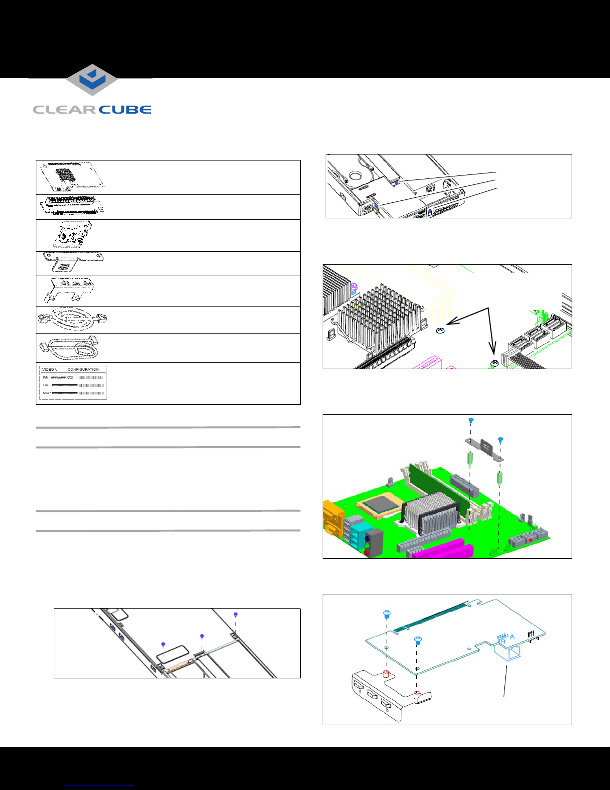
The V5120 Dual Host Card Upgrade Kit for A1410 blades
contains the following items:
V5120 Dual Host card—Provides
dual–monitor support.
Riser card—Attaches to V5120 card and to
blade motherboard
Mounting hardware—Two pan–head screws,
two SEMS screws, and two male–female
standoff screws
Support bracket
Mounting bracket
Ethernet cable
Four–pin signal cable
5120
Note: The upgrade kit is for A1410 blades only.
Video V5120 configuration label—Provides
part number, serial number, and card MAC
address. MAC address is critical for card and
blade configuration.
3. Remove the three screws from the I/O cover, located above the
power supply on the rear of the blade.
Remove
I/O cover screws.
4. Remove the two pan–head screws shown in the following figure
(the small heat sink is omitted for clarity). Insert the two standoff
screws (included in the kit) in the same holes. Use a hex–head
wrench to gently tighten the standoff screws.
Remove screws and save.
Insert standoff screws in
same holes.
5. Attach the support bracket to the standoffs using the 2 pan–
head screws you previously removed from the motherboard.
Ensure that the card support rails face up and face away from the
heat sink (heat sink omitted in the following figure).
System Firmware Compatibility
Ensure that the V5120 Dual Host card in your blade and the user
port to which the blade connects (I9420 I/Port thin client or C7420
C/Port) contain the compatible versions of firmware. For more
information, see support.clearcube.com.
Installing the V5120 Dual Host Card
Perform the following steps to install the V5120 upgrade kit. Use a #2
Phillips head screwdriver and, optionally, a ¼–inch hex–head wrench.
1.
Remove the A1410 blade from the chassis. If the blade is not in a
chassis, ensure that you disconnect power from the blade.
2. Remove the three screws from the top cover and remove the
cover from the blade.
6. Attach the V5120 card to the mounting bracket using the two
pan–head screws included in the upgrade kit. Ensure that the
Ethernet port is facing down, as shown in the following figure.
Ethernet Port
ClearCube Technology 8834 Capital of Texas Hwy N Austin, Texas 78759 voice 512 652 3500 www.clearcube.com
Page 2
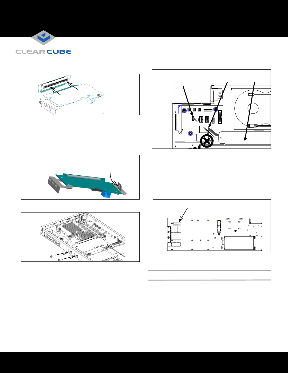
7. Align the V5120 card and the riser card, as shown in the
following figure. Gently insert the V5120 gold fingers into the
riser card’s slot. Ensure that the cards are fully seated.
8. Insert the cards in the motherboard expansion slot.
a. Lower the connected cards into the blade, and gently
place the edge of the V5120 card between the upper and
lower rails of the support bracket.
b. Align the riser card’s gold connectors with the 16x PCI
Express® expansion slot on the mother board. Press
down firmly to seat the riser card.
Place edge of card
between rails
9. Secure the mounting bracket to the top edge of the blade using
the two SEMS screws included in the kit.
Ensure that you thread the cables under the blade frame’s
center channel after connecting the cables.
Connect
4–Pin Cable
Here
Connect Ethernet
Cable Here
Center
Channel
11. Replace the top cover and the I/O cover and screw the covers
into place (see step 2 and step 3 for screw hole locations).
12. Remove the backing from the V5120 configuration label included
in the kit and place it on the outside of the A1410 blade frame.
Note: If a video card configuration label is already on the blade
in the indicated location (for example, if you are replacing
or upgrading an existing V5120 or V5140 card), ensure
that you remove the old label before applying the label in
the upgrade kit. If you cannot remove the old label, place
the new label on top of the existing label.
Place configuration label on outside of
blade frame in this location
10. Connect the Ethernet cable and the four–pin signal cable to
the matching connectors on the edge of the V5120 card.
– Connect the other end of the Ethernet cable to the single
Ethernet connector on the rear of the blade (do not
connect the cable to the dual Ethernet connector
adjacent to the power supply).
– Connect the other end of the signal cable to the four–pin
connector on the I/O motherboard on the rear of the blade
(the letters RGH are printed above the four–pin connector).
ClearCube Technology 8834 Capital of Texas Hwy N Austin, Texas 78759 voice 512 652 3500 www.clearcube.com
After installing the V5120 card, replace the blade in a cage and
reconnect power.
Additional Features and Information
See A–Series Data Center Products Reference Guide on
support.clearcube.com for more information about blade usage
and configuration, including topics such as:
• Mass storage lockout
• Network cabling and site preparation
• Chassis and blade installation
• Firmware compatibility
Email:
Web site: support.clearcube.com
Toll-free: (866) 652-3400
Phone: (512) 652-3400
support@clearcube.com
G0200107 Rev C
 Loading...