

Page 1
Clear-Com Encore
TM
TW-12C System Isolation Interface
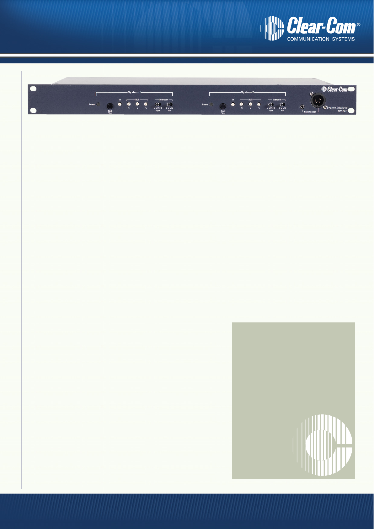
TW-12C Front Panel
Clear-Com’s TW-12C intercom system interface is designed for
connecting one intercom system to another, without compromising
the audio quality of either system.
Transparent Isolation Between Systems
The unique TW-12C completely eliminates hums and buzzes
caused by ground loops. The TW-12C compensates not only for
level differences between systems, but for varying impedances
caused by transformers and capacitance on the lines.
The TW-12C provides an electrically isolated interface between the
two intercom systems. Either “side” of the interface can connect to
a Clear-Com intercom system or an RTS intercom system, allowing
Clear-Com- to-Clear-Com, Clear-Com-to-RTS, and RTS-to-RTS
combinations. In addition, the TW-12C passes through and
translates “call” signals, Clear-Com-to-RTS and vice versa.
The interface consists of two identical, 2-wire-to-4-wire hybrid
networks which break the ground loops that occur when two
systems are run from separate power sources. The audio paths are
transformer-coupled and the signaling circuits are opto-isolated.
Fast, Easy & Accurate Setup
The operator can quickly set up the TW-12C by using a standard
intercom headset and the TW-12C’s built-in setup tone. The TW-12C
is capable of a range of null adjustments, allowing it to adapt to a
wide variety of line conditions, line lengths, and impedances.
The TW-12C provides each side of the system with null adjustment
controls that allow adjustment even when the system is operating.
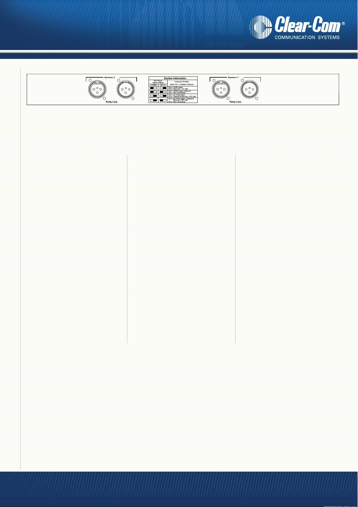
The rear panel of the TW-12C contains a pair of 3-pin XLR connectors (one male, one female) for each side of the interface.
Call Signal Translation
The TW-12C interface receives “Call” signaling in the appropriate form
(DC level for Clear-Com, tone for RTS), decodes it, and passes it to the
other side of the interface, via an optical coupler. The receiving side of
the interface sends the signal appropriate for the connected intercom.
Power
Each side of the TW-12C is powered
directly by the intercom system to which
it is connected. The unit draws about the
same amount of power as a belt-pack.
If either system is disconnected, the power
loss immediately shuts down the associated
electronics, eliminating any unwanted
noises on the operating intercom side.
The TW-12C front panel provides an
LED power indicator for each side of the
interface.
Features:
• Eliminates grounding problems
between intercom systems
• Matches gain between systems
• Provides system isolation for:
Clear-Com to Clear-Com;
Clear-Com to RTS; RTS to RTS
• Passes through and translates
signaling
• Provides superior hybrid nulling–
up to 40 dB
• Setup tone allows adjustment
during operation
• Powered from connected systems
• Uses just one rack space
www.clearcom.com
Page 2
Clear-Com Encore
TM
TW-12C System Isolation Interface
TW-12C Back Panel
Technical Specifications:
dBu is an absolute measurement. 0 dBu is
referenced to 0.775 volts RMS
Clear Comm Format
Line Characteristics
Max Level Before Clipping : >=3dBu
Impedance: >=10KΩ
Signalling
Receive: <=4 VDC
Send: >=11VDC
RTS Format
Line Characteristics
Max Level Before Clipping : >=5dBu
Impedance: >=10KΩ
Signalling Tone
Send frequency: 20kHz ±100Hz
Receive frequency: 20kHz ±500Hz
Send level: >=-6dBu
Receive level: <=-25dBu
General Characteristics
Frequency response:
Party-line - Party-line: 200-8KHz
Distortion
Party-line - Party-line: <=0.2%
Max Gain
ClearCom - RTS: >=9dB
ClearCom - ClearCom: >=4dB
RTS - ClearCom: >=-1dB
RTS - RTS: >=4dB
Min Gain
ClearCom - RTS: <=1dB
ClearCom - ClearCom: <=-4dB
RTS - ClearCom: <=-9dB
Power Requirements
Input Voltage Range: 20-30VDC
Input Current (average): <=50mA
Rear Panel Connectors
Rear panel: (2) XLR3M
(1 per channel)
(2) XLR3F
(1 per channel)
Front Panel Connectors
Headset: (1) XLR4M
TS1 Earphone: (1) 3.5mm Jack
Socket
Front Panel Controls and Indicators
Power: (2) Green LED
(1 per channel)
Null Test Button : (2) Buttons
(1 per channel)
Gain Level Adjust: (2) Controls
(1 per channel)
Null Adjust: (6) Controls
(3 per channel)
Connection Type Switch: (2) Switches
(1 per channel)
Pin Connection Select Switch: (2) Switches
(1 per channel)
Dimensions
1.75in. H x 19in. W x 7.25in. D
(45 x 483 x 185 mm)
Weight
5.63 lbs. (2.56 Kg)
Notice About Specifications
While Clear-Com makes every attempt to maintain the
accuracy of the information contained in its product
manuals, that information is subject to change without
notice. Performance specifications included in this manual
are design-center specifications and are included for
customer guidance and to facilitate system installation.
Actual operating performance may vary.
www.clearcom.com
Americas & Asia 850 Marina Village Parkway, Alameda, CA 94501 USA Tel: +1.510.337.6600
Europe, Middle East & Africa 7400 Beach Drive, IQ Cambridge, Cambridge, CB25 9TP UK Tel: +44 1223 815000
China Rm 706, Tower B, Derun Building, YongAn Dongli A No. 3, Jianwai Ave, Chaoyang District, Beijing 1000223 China Tel: 008610-8528-8748
Canada Clear-Com Research, 1440 Hocquart Street, Suite 221, St.-Bruno, Quebec J3V 6E Canada Tel: +1.450.653.9669
© 2009, Vitec Group Communications. All rights reserved. ® Clear-Com is a registered trade mark of The Vitec Group plc.
 Loading...