

Page 1

RS-603/623
BELTPACKS
INSTRUCTION MANUAL
Page 2

RS-603/623 Instruction Manual
©2005 Vitec Group Communications Inc.
All Rights Reserved
Part Number 810289, Rev. B
Vitec Group Communicatons Inc.
4065 Hollis Street
Emeryville, CA 94608-3505
U.S.A
Clear-Com is a registered trademark of Vitec Group
Communications Inc.
The Clear-Com Logo is a registered trademark of Vitec
Group Communications Inc.
Windows is a registered trademarks of Microsoft Corp.
Page 3

CONTENTS
INTRODUCTION. . . . . . . . . . . . . . . . . . . . . . . . . . . . 1
QUICK START . . . . . . . . . . . . . . . . . . . . . . . . . . . . . 5
OPERATING YOUR BELTPACK . . . . . . . . . . . . . . . . . . . . 7
Compatibility with Two-Wire (“TW”) Intercom Systems . . . 7
RS-603 and RS-623 Models . . . . . . . . . . . . . . . . . . . . . . . 8
RS-603R and RS-623R Models. . . . . . . . . . . . . . . . . . . . . 8
Controls and Adjustments . . . . . . . . . . . . . . . . . . . . . . . . . . . 9
CONNECTING THE BELTPACK . . . . . . . . . . . . . . . . . . . 19
Intercom Connector / Loop-Through Connector. . . . 19
Program-Audio Volume Control . . . . . . . . . . . . . . . . 21
Auxiliary (“AUX”) Headphone . . . . . . . . . . . . . . . . . . 21
Headset Connector. . . . . . . . . . . . . . . . . . . . . . . . . . . 22
Program-Audio Input Select Switch . . . . . . . . . . . . . . 22
Connector Pinouts. . . . . . . . . . . . . . . . . . . . . . . . . . . . 24
RS-603/623/R BELTPAC K S 1
Page 4

CUSTOMIZING YOUR BELTPACK . . . . . . . . . . . . . . . . . . 27
V-Pack Software. . . . . . . . . . . . . . . . . . . . . . . . . . . . . . . . . . 27
Onboard Programming . . . . . . . . . . . . . . . . . . . . . . . . . . . . 28
Settings You Can Customize . . . . . . . . . . . . . . . . . . . . . . 29
Mode Select. . . . . . . . . . . . . . . . . . . . . . . . . . . . . . . . . 30
Latch Disable. . . . . . . . . . . . . . . . . . . . . . . . . . . . . . . . 31
Call-on-Talk . . . . . . . . . . . . . . . . . . . . . . . . . . . . . . . . 33
Electret Microphone . . . . . . . . . . . . . . . . . . . . . . . . . . 34
Audible Call Signal . . . . . . . . . . . . . . . . . . . . . . . . . . . 35
Channel Swap . . . . . . . . . . . . . . . . . . . . . . . . . . . . . . . 36
Channel Exclusive . . . . . . . . . . . . . . . . . . . . . . . . . . . . 37
Monaural Headset (RS-623, RS-623R only) . . . . . . . . 38
Adjust Microphone Gain. . . . . . . . . . . . . . . . . . . . . . . 39
Lockout . . . . . . . . . . . . . . . . . . . . . . . . . . . . . . . . . . . . 41
Restoring the Factory Default Settings . . . . . . . . . . . . . . 42
SPECIFICATIONS . . . . . . . . . . . . . . . . . . . . . . . . . . 43
MAINTENANCE . . . . . . . . . . . . . . . . . . . . . . . . . . . 47
WARRANTY . . . . . . . . . . . . . . . . . . . . . . . . . . . . . 53
2 RS-603/623/R BELTPACKS
Page 5

INTRODUCTION
Thank you for choosing this product. Clear-Com designed the 600
series of beltpacks to meet the needs of all beltpack users, from
beginners to experienced professionals. For advanced users, the 600
series provides the most advanced level of functioning available.
You can choose from among seven different versions of beltpacks,
including single and dual-channel units, featuring both Clear-Com
and TW (two wire) compatibility.
RS-600 SERIES BELTPACKS
All RS-600 series beltpacks offer the following features:
• Rugged, compact design
• Full compatibility with existing Clear-Com party-line
systems
• Four setup configurations that you can activate directly from
the beltpack
• Extra 2.5 mm cell-phone type headset jack
• Advanced setup options with V-Pack software
RS-603/623/R BELTPACKS 1
Page 6

THE RS-603 SERIES
The RS-603 series features four models of beltpacks that are
compatible with two-wire (“TW”) intercom systems.
MODEL DESCRIPTION
RS-603 For use with Clear-Com TW products and a
monaural headset.
RS-623 For use with Clear-Com TW products and a
binaural headset.
RS-603R For use with RTS™-TW products and a
monaural headset
RS-623R For use with RTS™-TW products and a
binaural headset
These models include the following features:
• Two intercom channels
• Local input for program audio
• Program audio volume control
• 3-pin male XLR intercom connectors
• Choice of headset jacks for use with Clear-Com-TW or RTS-TW
systems, monaural or binaural audio
2 RS-603/623/R BELTP A C K S
Page 7

QUICK START
To start using your beltpack immediately:
1. Connect the appropriate 3-pin XLR line cables from an
active TW intercom line to the beltpack.
2. Turn down the beltpack’s incoming volume on each intercom
channel with the channel A and channel B volume-control
knobs.
3. Plug in a headset to the beltpack’s connector labeled
“headset.”
4. To talk on an intercom channel, press and hold the talk
button for the desired channel. Speak into the microphone in
your headset.
Note : If you tap the talk button twice in quick succession, the
talk button locks to the “on” setting (“latches”) for hands-free use.
Press the talk button again to unlatch it. RS-603R and
RS-623R models initially power up in RTS-mode, in which a
talk button latches with a single tap. You can change this setting
with onboard controls or with the V-Pack software. See the
chapter “Customizing Your Beltpack” later in this manual for
information on programming a beltpack.
RS-603/623/R BELTPACKS
5
Page 8

5. Adjust the sidetone and incoming volume levels for both
channels as you and others on the channels speak at the
anticipated levels for the application.
6. To send a call signal, press the button labeled “call” for the
appropriate channel.
6
RS-603/623/R BELTPACKS
Page 9

OPERATING YOUR BELTPACK
COMPATIBILITY WITH TWO-WIRE (“TW”) INTERCOM SYSTEMS
Clear-Com designed the RS-603, RS-623, RS-603R, and RS-623R
series of beltpacks to operate with “TW” (two wire) systems. These
beltpacks have the appropriate audio levels and frequency response
curves for operating on a TW intercom line, as well as having such
TW features as AC call signaling and remote microphone shutoff.
The RS-603 and RS-623 models are shipped ready to operate on
Clear-Com TW intercom lines, while the RS-603R and RS-623R
models are shipped ready to operate on RTS-TW intercom lines.
However, using a beltpack’s onboard controls, you can easily
reprogram any of these models to work on the opposite system. For
example, you can program a Clear-Com TW-compatible beltpack to
operate on an RTS intercom line, and program an RTS-compatible
beltpack to operate on a Clear-Com TW intercom line.
For more information about programming a beltpack, see the chapter
“Customizing Your Beltpack.”
RS-603/623/R BELTPACKS
7
Page 10

RS-603 AND RS-623 MODELS
All previous versions of Clear-Com TW beltpacks and stations work
compatibly with the RS-603 and RS-623 beltpacks. The RS-603
beltpack operates with a monaural headset, while the RS-623 beltpack
operates with a binaural headset.
RS-601 beltpack models are compatible with Clear-Com TW
products and can be mixed on an intercom channel with RS-603
series units that are operating in Clear-Com mode.
RS-603R AND RS-623R MODELS
The RS-603R and RS-623R beltpacks feature female rather than male
headset jacks. The RS-603 beltpack operates with a monaural headset,
while the RS-623R beltpack operates with a binaural headset.
The RS-623R beltpack features a 5-pin female headset jack. Although
this model’s headset jack is programmed for monaural operation, it is
capable of split-ear operation with a compatible headset. You can
program the beltpack to operate with a monaural headset using the
beltpack’s onboard controls or the V-Pack software.See the chapter
“Customizing Your Beltpack” for more information.
8
R S - 6 0 3 / 6 2 3 / R B E L T P A C K S
Page 11
CONTROLS AND ADJUSTMENTS
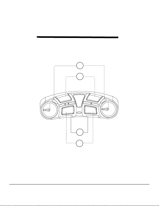
Figures 1 and 2 illustrate the beltpack’s onboard controls and
adjustments.
5BMLMJHIUTDIBOOFMT"BOE#
5BMLCVUUPOTDIBOOFMT"BOE#
TALK A
CALL A
TAL K B
CALL B
$BMMMJHIUTDIBOOFMT"BOE#
$BMMCVUUPOTDIBOOFMT"BOE#
Figure 1: RS-603 Series Control Panel
RS-603/623/R BELTPACKS
9
Page 12

1
Talk Lights, Channels A and B
A channel’s green talk light illuminates when you press or latch that
channel’s talk button.
Some onboard programming options can change the function of this
light. For more information about onboard programming, refer to
“Customizing Your Beltpack” later in this manual
2
Talk Buttons, Channels A and B
To talk on an intercom channel, press and hold that channel’s talk
button while speaking into the microphone in your headset. While
you hold the button, your voice transmits to the intercom channel.
When you release the button, your voice no longer transmits to the
intercom channel.
To “latch” a talk button “on” for hands-free use, quickly tap the
button twice. To unlatch the talk button, press the button again.
With the V-Pack programming software, you can program a talk
button to latch with a single or double tap, or not to latch at all. See
“Customizing Your Beltpack” for more information.
Call Lights, Channels A and B
3
A channel’s call light illuminates when you send or receive a call signal
on that channel.
1 0
R S - 6 0 3 / 6 2 3 / R B E L T P A C K S
Page 13

Some onboard and computer programming options can change the
function of this light. See “Customizing Your Beltpack” for more
information.
4
Call Buttons, Channels A and B
When you press a channel’s call button, a call signal is sent to all other
stations on that channel. Pressing the Call A button sends a call signal
on channel A. Pressing the Call B button sends a call signal on
channel B.
A channel’s call light glows red to indicate both outgoing and
incoming call signals on the channel.
Note: Depending on the type and length of cables attached to the beltpack,
crosstalk between cables may cause both channels to indicate a 20 kHz AC
call signal that is sent on only one channel.
5
Volume-Control Knob, Channel A
The volume-control knob for channel A adjusts the incoming volume
level (“listen level”) for that channel.
There is a limiter built into the beltpack circuitry to prevent incoming
volume from exceeding a safe level. You can suspend this limit with
the V-Pack software.
The volume A control knob also adjusts mic gain (either main or
auxiliary). Refer to “Customizing Your Beltpack” for more
information on adjusting outgoing volume.
RS-603/623/R BELTPACKS
11
Page 14

6
Volume-Control Knob, Channel B
The volume-control knob for channel B adjusts the incoming volume
level (“listen level”) for that channel
There is a limiter built into the beltpack circuitry to prevent incoming
volume from exceeding a safe level. You can suspend this limit with
the V-Pack software.
Power Status Light
7
An illuminated power status light indicates that the beltpack is
connected to a powered intercom line.
Note: The light may illuminate even if the beltpack is receiving less
than the minimum 12 VDC required for beltpack operation.
1 2
R S - 6 0 3 / 6 2 3 / R B E L T P A C K S
Page 15
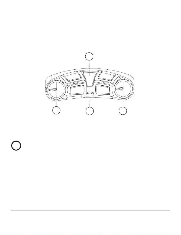
7PMVNF±DPOUSPMLOPCDIBOOFM"
7PMVNF±DPOUSPMLOPCDIBOOFM#
1PXFS±TUBUVTMJHIU
4FUVQJOGPSNBUJPOXJOEPX
TALK A
CALL A
TAL K B
CALL B
Figure 2: RS-603 Series Control Panel
Setup Information Window
8
When you press and hold the setup button for more than three
seconds, the setup information window lights up and displays current
beltpack programming information.
If you do not select or program a feature within five seconds, setup is
cancelled, and the setup information window dims to indicate that
RS-603/623/R BELTPACKS
13
Page 16
the setup mode is no longer available. This feature prevents changes if
the setup button is pressed accidentally.
For more information on programming features from your beltpack,
see “Customizing Your Beltpack.”
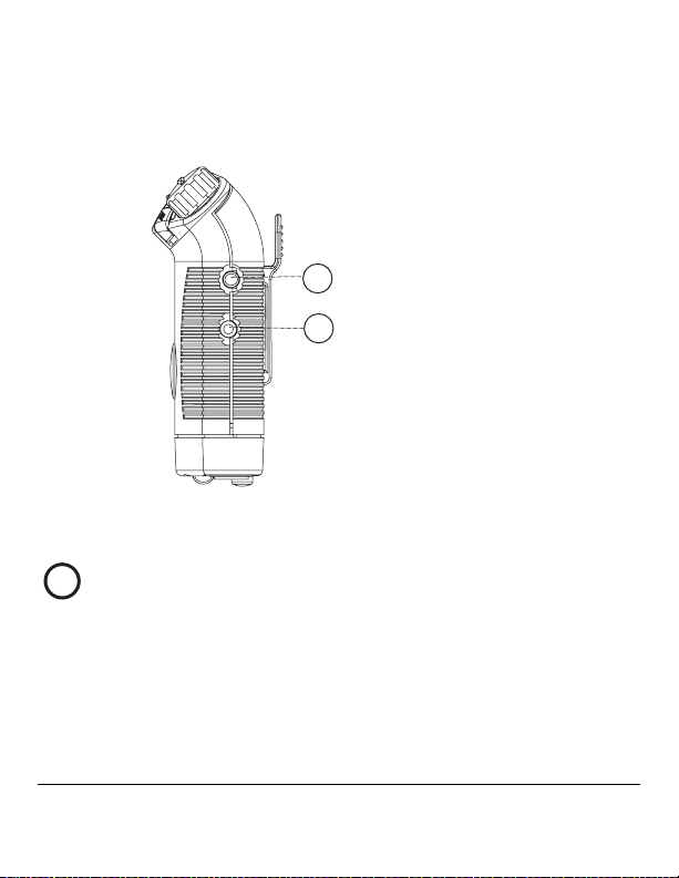
4FUVQCVUUPO
$PNQVUFSDPOOFDUPS
NNKBDL
Figure 3: Side panel of RS-602/622 Beltpack
Setup Button
9
When you press and hold the blue setup button for approximately
three seconds, the beltpack enters “setup mode” during which you can
select certain operating features for the beltpack.
1 4
R S - 6 0 3 / 6 2 3 / R B E L T P A C K S
Page 17

Once setup mode is active, if you do not select or program a feature
within five seconds, the setup mode deactivates, and the beltpack goes
back to its normal state.
See “Customizing Your Beltpack” on page 25 for information on
programming your beltpack with this feature.
Computer Connector
10
You can program your beltpack from a computer using the V-Pack™
programming software. To use this software you must first physically
connect the beltpack to a computer with Clear-Com’s VPC-1 cable or
its equivalent.
The VPC-1 cable has a tip-ring-sleeve 3.5 mm plug at one end for
connecting to the beltpack, and a DB-9F plug at the other end for
connecting to a computer’s serial port.
To connect the VPC-1 cable from your beltpack to a computer:
1. Plug the 3.5 mm plug at one end of the cable into the beltpack’s
3.5 mm jack located just under the setup button.
2. Plug the DB-9F plug on the other end of the cable into the DB-
9M serial port socket on a computer.
If your computer has only USB ports rather than a serial port, you
must purchase a USB-to-serial port adaptor.
Contact your dealer or the Clear-Com factory for information about
obtaining the beltpack programming kit, which contains the V-Pack
software, VPC-1 cable, and V-Pack manual. You can also find a PDF
of the V-Pack manual at www.clearcom.com.
RS-603/623/R BELTPACKS
15
Page 18
PIN FUNCTION
Tip SDO to computer
Ring SDI from computer
Sleeve Ground
Table 1: Pinouts for computer connector
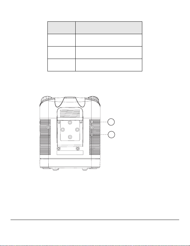
4JEFUPOFBEKVTU
DIBOOFM"
4JEFUPOFBEKVTU
PP4*%&50/&P
DIBOOFM#
Figure 4: Sidetone controls for channels A and B
1 6
R S - 6 0 3 / 6 2 3 / R B E L T P A C K S
Page 19

Sidetone Control, Channel A
11
Sidetone Control, Channel B
12
To adjust the beltpack’s “sidetone,” or the level of one’s own voice in
the headset, insert a small flat-headed screwdriver into one of the two
holes labeled “sidetone” on the back of the beltpack, as shown in
Figure 4.
The upper control adjusts the sidetone for channel A. The lower
control adjusts the sidetone for channel B.
Turn the screwdriver until you can no longer hear any sidetone in the
headset. This is called the “null” setting.
When you turn the screwdriver again, either clockwise or
counterclockwise, the sidetone increases. Adjust the sidetone so that it
is somewhere in the mid-range of possible settings, at a level that feels
comfortable to you.
The need for an extreme sidetone setting to either limit could indicate
a problem with the overall intercom system, such as lack of
terminations or multiple terminations. A malfunctioning headset
could also be the cause. Do not force the sidetone adjustment control
past its stop points as this will damage it.
Note: The small raised dots next to the sidetone controls help you to
identify the correct control in darkened environments. The channel A
control has one raised dot adjacent to it. The channel B control has two
raised dots adjacent to it.
RS-603/623/R BELTPACKS
17
Page 20

1 8
R S - 6 0 3 / 6 2 3 / R B E L T P A C K S
Page 21

CONNECTING THE BELTPACK
A beltpack connects to the intercom line by connecting to a main
station, power supply, or another beltpack. You must also connect a
headset to the beltpack and, optionally, a computer for programming
beltpack options with the V-Pack software.
The following table lists the connectors for the RS-603 series of
beltpacks. Figure 5 illustrates the connectors for an RS-603 beltpack
CONNECTOR RS-603 RS-623 RS-603R RS-623R
Intercom 3-pin F 3-pin F 3-pin M 3-pin M
Loop-through 3-pin M 3-pin M 3-pin F 3-pin F
Aux headset 2.5 mm 2.5 mm 2.5 mm 2.5 mm
Headset 4-pin M 6-pin M 4-pin F 5-pin F
Table 1: Connectors for RS-603 Series of Beltpacks
1
Intercom Connector / Loop-Through Connector
Figure 1 illustrates the “intercom” and “loop-through” connectors on
an RS-603 beltpack. The beltpack connects to a main station, power
supply, or to other beltpacks with the connector labeled “intercom.”
The “loop-through” connector connects the beltpack to the intercom
line or to another beltpack (“looping through”).
RS-603/623/R BELTPACKS
19
Page 22

The loop-though connector becomes a program-audio input
connector when you select that option with the slide switch located
directly next to the connector. See the section “Program-Input Select
Switch” below for more information.
Note: On the RS-603R and RS-623R models, the intercom and
loop-through connectors swap places, in the RTS style.
2 0
*OUFSDPN$POOFDUPS
-PPQ±5ISPVHI$POOFDUPS
1SPHSBN±"VEJP7PMVNF$POUSPM
"VYJMJBSZ)FBEQIPOF$POOFDUPS
)FBETFU$POOFDUPSWBSJFTXJUIFBDINPEFM
1SPHSBN±"VEJP*OQVU4FMFDU4XJUDI
Figure 1: RS-603 Connector Panel
R S - 6 0 3 / 6 2 3 / R B E L T P A C K S
Page 23

Program-Audio Volume Control
3
You can adjust the volume level of the program audio by rotating the
program audio volume control. If necessary, you can mute the
program audio by turning the knob all the way down.
The program audio is transformer isolated and accepts line level
signals in the –20 to +10 dBv range.
4
Auxiliary (“AUX”) Headphone
Clear-Com designed the auxiliary headset connector, labeled “AUX,”
for use with the CC-25 Ultra-Light headset. The beltpack’s circuitry is
designed to work with the CC-25 headset to produce excellent quality
sound.
While certain types of mobile-phone style headsets will fit the 2.5 mm
AUX jack, using these headsets degrades system performance due to
reduced audio bandwidth and reduced noise rejection at the
microphone. You can use such mobile-phone style headsets more
reliably with listen-only applications.
The AUX connector provides bias voltage for electret microphones.
With V-Pack, you can also program this connector for use with
dynamic microphones.
Note: Using multiple mobile-phone style headsets in a system could
adversely affect nulling, crosstalk, and overall system performance.
RS-603/623/R BELTPACKS
21
Page 24

5
Headset Connector
You connect a headset to the beltpack at the connector labeled
“headset.” The RS-603 series beltpacks have varying types of headset
connectors. See Table 1 for a list by model number.
The headset connector is always active and has priority if a second
headset is connected to the auxiliary (“AUX”) connector. Generally
you should connect only one headset at a time to a beltpack.
All RS-603 series models provide power to an electret microphone.
The microphone’s gain automatically adjusts to an electret
microphone. See “Specifications” for impedance requirements.
Program-Audio Input Select Switch
6
To transform the “loop-through” connector to a program-audio input
connector, move the slide switch toward the headset connector, in the
direction labeled on the beltpack as “PGM.”
Note: Placing the switch in the “program” (PGM) position while the jack
is still connected to the intercom channel causes the beltpack to lose power
and the channel to short out.
When you do so, the loop-through connector becomes a program
audio input connector, disabling the loop-through function of the
connector.
The program input is transformer isolated and accepts line level
signals in the –20 to +10 dBV range.
2 2
R S - 6 0 3 / 6 2 3 / R B E L T P A C K S
Page 25

To adjust the program audio volume, rotate the knob located on the
bottom panel of the beltpack.
To restore the connector to its “loop-through” function, slide the
switch back towards the “loop-through” connector, in the direction
labeled on the beltpack as “intercom.”
Note: In some instances, connecting a source of program audio may cause
a hum in the system. To remedy this, remove the internal jumper from
pins 1 and 2 of P2 and connect the jumper to pin 2 only. This removes
the ground and leaves only a balanced, transformer-isolated connection.
To gain access to the jumper, remove the beltpack’s back cover by removing
the four screws.
RS-603/623/R BELTPACKS
23
Page 26

CONNECTOR PINOUTS
Intercom Connector Pinouts
PIN FUNCTION
603 623 603R 623R
1 ground ground ground ground
2 +30 VDC/
CH. A *
3 CH. B CH. B CH. B CH. B
+30 VDC /
CH. A *
+ 30 VDC /
CH. A *
+30 VDC /
CH. A *
Loop-Through Connector Pinouts
PIN FUNCTION
603 623 603R 623R
1 ground ground ground ground
2 +30 VDC /
CH. A /
program in (+)
3CH. B /
program in (-)
* The beltpack draws power from pin 2 of the XLR. Alternatively, the
beltpack can draw power from pin 3 of the XLR. To accomplish this,
unplug the internal jumper from pins 2 and 3 of P1 and connect it to pins
1 and 2 instead. To gain access to the jumper, remove the beltpack’s pack
cover by removing the four screws.
+30 VDC /
CH. A /
program in (+)
CH. B /
program in (-)
+ 30 VDC /
CH. A /
program in (+)
CH. B /
program in (-)
+30 VDC /
CH. A /
program in (+)
CH. B /
program in (-)
2 4
R S - 6 0 3 / 6 2 3 / R B E L T P A C K S
Page 27

Note; On the RS-603R and RS-623R models, the intercom and
loop-through connectors swap positions to conform to RTS
requirements.
Auxiliary Headset Connector Pinouts
PIN FUNCTION
603 623 603R 623R
Tip microphone microphone microphone microphone
Ring earphone earphone earphone earphone
Sleeve common common common common
Computer Connector Pinouts
PIN FUNCTION
603 623 603R 623R
Tip SDO to
computer
Ring SDI from
computer
Sleeve ground ground ground ground
SDO to
computer
SDI from
computer
SDO to
computer
SDI from
computer
SDO to
computer
SDI from
computer
RS-603/623/R BELTPACKS
25
Page 28

Headset Connector Pinouts
PIN FUNCTION
603 623 603R 623R
1 Mic (L) Mic (L) Mic (L) Mic (L)
2 Mic (H) Mic (H) Mic (H) Mic (H)
3 Headphone (L) Headphone
common
4 Headphone (H) Ch. B
headphone (H)
5Ch. A
headphone (H)
6Headphone
common
Headphone (L) Headphone
common
Headphone (H) Ch. B
headphone (H)
Ch. A
headphone (H)
2 6
R S - 6 0 3 / 6 2 3 / R B E L T P A C K S
Page 29

CUSTOMIZING YOUR BELTPACK
You can customize an RS-600 series beltpack for quick adaptation to
the needs of any working environment. There are two methods for
customizing your beltpack’s settings:
• Using a beltpack’s onboard controls
• Using the V-Pack programming software
This manual describes programming a beltpack with the onboard
controls, and only briefly describes V-Pack. The V-Pack programming
software has its own manual, which you can view and download at
www.clearcom.com.
Note: You may also refer to the printed guide on the back of the beltpack for
quick instructions on setting up the beltpack with the onboard controls.
V-PACK SOFTWARE
The V-Pack programmming software gives you access to the full range
of options for customizing your beltpack. For example, you can
program a call signal to appear as a steady or flashing light, a bright or
dim light, or a tone. You can activate and adjust a noise gate. You can
set a minimum headset level.
A unique V-Pack feature is to create one custom setup and quickly
transfer it to several beltpacks with the “beltpack cloning” feature. This
RS-603/623/R BELTPACKS
27
Page 30

feature is useful for programming many beltpacks with the same
settings. And V-Pack includes many more features you can program
for your beltpack.
To operate the V-Pack software, you must first install it on a computer,
then connect the VPC-1 cable to both a beltpack and to your
computer.
For more detailed instructions on using the software, see the V-Pack
manual or on-line help files. You can access the manual from the
Clear-Com Web site. A VPC-1 installation kit, which includes a
factory CD containing the V-Pack software, a computer cable, and a
printed V-Pack manual is available for purchase through your dealer
or directly from Clear-Com.
ONBOARD PROGRAMMING
With onboard programming, you customize the operation of your
beltpack using the controls on the beltpack itself.
When you receive your beltpack, it already contains the default
settings that will meet the needs of most users. You do not need to
program it unless you want to.
However, if you wish to change the settings to better meet your needs,
you can do so with onboard programming. The beltpack remembers
your new settings until you change them again.
28
RS-603/623/R BELTPACKS
Page 31

SETTINGS YOU CAN CUSTOMIZE
Table 1 shows the beltpack functions you can customize with onboard
controls. Note than each function is assigned a number, which you will
refer to for programming.
FUNCTION # NAME STATUS CHANNELS
Function 1 Mode Select 1,2,3,4 Both A and B
Function 2 Latch disable on or off A or B
Function 3 Talk disable on or off A or B
Function 4 Call-on-talk on or off A or B
Function 5 Electret mic (headset) on or off Both A and B
Function 6 Call Tone (in earphone) on or off A or B
Function 7 Channel swap on or off Both A and B
Function 8 Channel exclusive on or off A or B
Function 9 Mono (binaural models only) on or off Both A and B
Function A Adjust Microphone Gain variable Both A and B
Function L Locks out onboard access on or off Both A and B
Table 1: Functions You Can Edit With Onboard Controls
Before you program the beltpack with the onboard controls, the
beltpack must be connected to an intercom line and receiving power,
and must not be connected to a computer.
You can program most functions to operate on channel A, channel B,
or both. However, some functions affect both channels. Table 1 shows
if a function affects one or both channels.
RS-603/623/R BELTPACKS
29
Page 32

Mode Select, Function 1
A “mode” is one complete “package” of settings for a beltpack. Each
beltpack’s memory holds four modes. You can easily select and activate
any one of the four modes directly from the beltpack.
When you receive your beltpack, each of the four modes is
preprogrammed with the Clear-Com default settings. Each mode is
similar to the others, with only minor variations.
With onboard setup, you can select any one of the four modes and
change specific settings to your requirements. Editing a mode’s
settings automatically saves them in the beltpack’s nonvolatile
memory.
To select a mode:
1. Press and hold the setup button until the setup information
window displays a “P” and then release the button.
2. Press and release the Talk A button. A winking number appears in
the display. This is the currently selected mode.
Note: A “winking” light flashes three times per second.
3. To select a new mode, press the Talk A button to scroll through the
four possible modes, 1 through 4.
4. When the desired mode appears in the display, press the setup
button to select the mode and to exit setup.
The selected mode becomes the active mode for both beltpack
channels. If you do not press a button within five seconds, the
beltpack exits the setup program without making any changes.
30
RS-603/623/R BELTPACKS
Page 33

Latch Disable, Function 2
A beltpack’s talk button normally latches when you tap it twice. If you
select to disable this function, the talk button does not latch.
This setting is recommended if you use the call-on-talk feature, which
causes the beltpack to send a call signal each time you press the talk
button.
To select “latch disable” for a channel:
1. Press and hold the setup button until the setup information window
displays a “P” and then release the button.
2. Repeatedly press the Call A button until “2” appears in the display.
3. Press the appropriate channel’s talk button (Talk A or Talk B) to
toggle “latch disable” either on or off for that channel.
• A channel’s talk light reveals the function’s status for that channel.
If the talk light is on, “latch disable” is on; if the talk light is off,
“latch disable” is off.
• You can set latch disable for one or both channels.
4. When you have made your selections, press the setup button to save
them and to exit setup, or press the Call A button to select other
functions to program.
If you do not press a button within five seconds, the beltpack exits the
setup program without making any changes.
RS-603/623/R BELTPACKS
31
Page 34

Talk Disable, Function 3
This function turns the talk button on or off. When disabled, the talk
button does not function.
Set the talk button to off when you wish to operate the beltpack as a
listen-only device.
To select “talk disable” for a channel:
1. Press and hold the setup button until the setup information
window displays a “P” and then release the button.
2. Repeatedly press the Call A button until “3” appears in the display.
3. Press the appropriate channel’s talk button (Talk A or Talk B) to
toggle “talk disable” either on or off for that channel.
• A channel’s talk light reveals the function’s status for that
channel. If the talk light is on, “talk disable” is on for that
channel; if the talk light is off, “talk disable” is off for that
channel.
• You can set talk disable for one or both channels.
4. When you have made your selections, press the setup button to save
them and to exit setup, or press the Call A button to select other
functions to program.
If you do not press a button within five seconds, the beltpack exits the
setup program without making any changes.
32
RS-603/623/R BELTPACKS
Page 35

Call-on-Talk, Function 4
This function causes a beltpack to send a call signal each time you press
or latch the talk button. You can toggle this function on or off.
When using “call-on-talk,” it is recommended that you set the talk
button for non-latching operation. Call-on-talk is useful when
operating call-signal based components such as the Clear-Com TW-40
2-way radio interface and the Clear-Com KB-212 speaker station.
To select “call-on-talk” for a channel:
1. Press and hold the setup button until the setup information window
displays a “P” and then release the button.
2. Repeatedly press the Call A button until “4” appears in the display.
3. Press the appropriate channel’s talk button (Talk A or Talk B) to
toggle “call-on-talk” either on or off for that channel.
• A channel’s talk light reveals the function’s status for that channel.
If the talk light is on, “call-on-talk” is on for that channel; if the
talk light is off, “call-on-talk” is off for that channel.
• You can set call-on-talk for one or both channels.
4. When you have made your selections, press the setup button to save
them and to exit setup, or press the Call A button to select other
functions to program.
If you do not press a button within five seconds, the beltpack exits the
setup program without making any changes.
RS-603/623/R BELTPACKS
33
Page 36

Electret Microphone, Function 5
This function allows a beltpack to operate with an electretmicrophone equipped headset. It only affects a headset connected to
the main headset jack. Toggling the function to off reverts the
beltpack to dynamic microphone operation.
To select “electret microphone” for a channel:
1. Press and hold the setup button until the setup information
window displays a “P” and then release the button.
2. Repeatedly press the Call A button until “5” appears in the display.
3. Press the Talk A button to toggle “electret microphone” either on
or off.
• If the talk lights are on, the “electret microphone” option is on;
if the talk light is off, the “electret microphone” option is off.
• The “electret microphone” option affects both channels.
4. When you have made your selections, press the setup button to save
them and to exit setup, or press the Call A button to select other
functions to program.
If you do not press a button within five seconds, the beltpack exits the
setup program without making any changes.
34
RS-603/623/R BELTPACKS
Page 37

Audible Call Signal, Function 6
When this function is on, the beltpack produces an audible call signal
in the headset when a call signal is received.When this function is off, it
does not.
The audible call signal’s volume level is preset. (Volume may vary
slightly, depending on headset.) This function is useful for unspoken
cues when a visual call signal is not practical or effective.
To select an “audible call signal” for a channel:
1. Press and hold the setup button until the setup information window
displays a “P” and then release the button.
2. Repeatedly press the Call A button until “6” appears in the display.
3. Press the appropriate channel’s talk button (Talk A or Talk B) to
toggle “audible call signal” either on or off for that channel.
• A channel’s talk light reveals the function’s status for that channel.
If the talk light is on, “audible call signal” is on for that channel;
if the talk light is off, “audible call signal” is off for that channel.
• You can select “audible call signal” for one or both channels.
4. When you have made your selections, press the setup button to save
them and to exit setup, or press the Call A button to select other
functions to program.
If you do not press a button within five seconds, the beltpack exits the
setup program without making any changes.
RS-603/623/R BELTPACKS
35
Page 38

Channel Swap, Function 7
When toggled to the “on” setting, this function reverses the beltpack’s
audio channels so that channel A appears on channel B and channel B
appears on channel A. Channel A’s controls operate channel B and
channel B’s controls operate channel A.
Audio on pins 3 and 4 of the intercom channel are reversed to pins 4
and 3.
To select “channel swap” for a channel:
1. Press and hold the setup button until the setup information
window displays a “P” and then release the button.
2. Repeatedly press the Call A button until “7” appears in the display.
3. Press the Talk A button to toggle “channel swap” either on or off.
• If both talk lights are on, “channel swap” is on; if both talk lights
are off, “channel swap” is off.
• The “channel swap” option affects both channels.
4. When you have made your selections, press the setup button to save
them and to exit setup, or press the Call A button to select other
functions to program.
If you do not press a button within five seconds, the beltpack exits the
setup program without making any changes.
36
RS-603/623/R BELTPACKS
Page 39

Channel Exclusive, Function 8
This function causes the beltpack to operate with only one active
channel. You select one of the beltpack’s two channels to operate as the
“exclusive” channel.
When you select an exclusive channel, the beltpack’s two sets of talk
and call buttons operate for only the selected channel. The selected
channel’s volume-control knob operates, while the beltpack’s second
volume-control knob does not operate.
To select an “exclusive” channel:
1. Press and hold the setup button until the setup information window
displays a “P” and then release the button.
2. Repeatedly press the Call A button until “8” appears in the display.
3. Press the appropriate channel’s talk button (Talk A or Talk B) to
toggle “channel exclusive” either on or off for that channel.
• A channel’s talk light reveals the function’s status for that channel.
If the talk light is on, “channel exclusive” is on for that channel; if
the talk light is off, “channel exclusive” is off for that channel.
• You can select either channel A or channel B to operate as the
exclusive channel.
4. When you have made your selections, press the setup button to save
them and to exit setup, or press the Call A button to select other
functions to program.
If you do not press a button within five seconds, the beltpack exits the
setup program without making any changes.
RS-603/623/R BELTPACKS
37
Page 40

Monaural Headset (RS-623, RS-623R only), Function 9
Normally, channel A audio goes to the right earphone of a headset and
channel B audio goes to the left earphone.
When set to “on,” this function sends audio from both channels A and
B to each earphone.
Note: The RS-623 default option is “split ear.” The RS-623R default
option is monaural audio to headset.
To select “split-ear headset” for a channel:
1. Press and hold the setup button until the setup information
window displays a “P” and then release the button.
2. Repeatedly press the Call A button until “9” appears in the display.
3. Press the Talk A button to toggle “split-ear headset” either on or
off.
• A beltpack’s talk lights reveal the function’s status. If both talk
lights are on, “split-ear headset” is on; if both talk lights are off,
“split-ear headset” is off for that channel.
• The split-ear headset option affects both channels.
4. When you have made your selections, press the setup button to save
them and to exit setup, or press the Call A button to select other
functions to program.
If you do not press a button within five seconds, the beltpack exits the
setup program without making any changes.
38
RS-603/623/R BELTPACKS
Page 41

Adjust Microphone Gain, Function A
The microphone “gain” setting allows you to reduce the gain of the mic
preamplifier by up to 12 dB. This feature affects both channels. You use
the Channel A volume knob to adjust the microphone gain.
To adjust microphone gain:
1. Connect the main or auxiliary headset to the beltpack, depending
upon which mic gain you would like to adjust.
2. Press and hold the setup button until the setup information window
displays a “P” and then release the button.
3. Repeatedly press the Call A button until “A” appears in the display.
The talk light for channel A blinks to indicate that you use the
channel A volume knob to adjust the gain.
4. Turn the channel A volume knob clockwise to increase the gain and
counterclockwise to decrease it.
As you turn the knob, the setup information window displays a
circular progress indicator. When the gain is set to its highest
setting, the indicator lights up at the most clockwise position on the
display. As you adjust the gain downwards, the progress indicator
correspondingly moves counterclockwise on the display, until it is at
its lowest setting. Turning the volume knob after the light has
reached its highest or lowest setting will not further affect the gain.
5. Press the setup button to save the changes and exit the setup
program or press the Call A button to select other functions to
program.
RS-603/623/R BELTPACKS
39
Page 42

The gain adjustment affects only the microphone of the currently
connected headset. If you unplug this headset and connect the
secondary headset (either main or auxiliary) the settings for that
headset remain the same as previously programmed.
If you do not press a button within five seconds, the beltpack exits the
setup program without making any changes.
40
RS-603/623/R BELTPACKS
Page 43

Lockout, Function L
“Lockout” allows you to prevent all editing of beltpack functions with
onboard controls.
When you select “lockout,” you can access the on-off status of
functions with the onboard controls, but you cannot edit them. You
cannot access information which mode is active.
To regain access to editing, you can either restore the factory default
settings from the beltpack itself, or use the V-Pack software.
To select “lockout” for a channel:
1. Press and hold the setup button until the setup information window
displays a “P” and then release the button.
2. Repeatedly press the Call A button until “L” appears in the display.
3. Press the Talk A button to toggle “lockout” either on or off.
• The beltpack’s talk lights reveal the function’s status. If both talk
lights are on, “lockout” is on; if both talk lights are off, “lockout”
is off.
• The lockout option affects both channels and all modes.
4. When you have made your selections, press the setup button to save
them and to exit setup, or press the Call A button to select other
functions to program.
If you do not press a button within five seconds, the beltpack exits the
setup program without making any changes.
RS-603/623/R BELTPACKS
41
Page 44

RESTORING THE FACTORY DEFAULT SETTINGS
To restore the factory default settings for all four modes:
1. Press and hold the setup button until the setup information
window displays a “P” and then release the button.
2. Press and hold the Call A button. The display changes from “1” to
“2.”
3. While still holding the call button down, press the setup button.
The display momentarily shows an “F” to indicate that the
beltpack is now programmed with the factory default settings.
4. Release the setup button and the call button.
The beltpack resumes operation with the factory default settings.
42
RS-603/623/R BELTPACKS
Page 45

SPECIFICATIONS
0 dBv is referenced to 0.775 V RMS
General
Amplifier Design: I.C. amplifiers, including solid-state digital
switching and signaling circuits. Current-limited and
short-circuit protected.
Signal to Noise: >75 dB
Bridging Impedance: >15k
Line Level: -14 dB, +5 dB max.
Sidetone Adjust: >35 dB
EMI and RFI rejection: >60 dB
Microphone Pre-Amplifier
Headset Mic Impedance: 200 ohms
Gain, mic to line: 41 dB (dynamic)
Limiter Range: 26 dB
Frequency Response: 200 Hz – 12 kHz contoured for
intelligibility
RS-6 0 3/623 / R BEL T PACKS 43
Page 46

Program Input
Program input Balanced, transformer isolated
Input sensitivity: –20 dBv to +10 dBv
Frequency response 50 Hz – 18 Hz, ± 2 dB
Headphone Amplifier
Load Impedance: 50 - 2,000 ohms
Output Level: +17 dBv before clipping
Distortion: <0.1% THD @ 1 kHz
Gain, line to output: +34 dB
Frequency Response: 100 Hz - 18 kHz, ±2dB
Connectors
Intercom Line: (2) 3-pin XLR–M–F
Headset: RS-603/623: 4-pin XLR–M
RS-603R: 4-pin XLR–F
RS-623R: 5-pin XLR-F
Power Requirements
RS-602/622 55mA quiescent
62mA average talk, both channels
simultaneously
44 RS -603/623/R BELTPACKS
Page 47

Power Requirements (continued)
50mA talk with signaling, both channels
simultaneously
DC Voltage Range: 12-32 volts
Environmental
Operating Temp. Range: 0°C - 70°C (32°F - 158° F)
Humidity: 0 - 90% relative humidity
Dimensions
4.58"H x 3.73"W x 1.34"D (116 x 95 x 34 mm)
Weight
7.8 oz. (0.22 kg)
Specifications subject to change without notice.
RS-6 0 3/623 / R BEL T PACKS 45
Page 48

46 RS -603/623/R BELTPACKS
Page 49

MAINTENANCE
GENERAL USAGE NOTES
Cabling choices can greatly impact the performance of an intercom
system. Length, gauge, and shield quality, as well as routing, must all
be considered. For two-pair cable, crosstalk performance is affected
both by length and DC resistance of the shield (the lower the better).
The quality of the headset cable can affect crosstalk, particularly in
large systems.
Note: For more information on installing a party-line system, see the
Party-Line Installation Manual.
A beltpack’s headphone amplifier accommodates impedances from 50
to 2000 ohms. The mic preamplifier accommodates impedances
from 50 to 1000 ohms. Output level is more critical to optimal
performance than the impedance. Higher impedances may require
more microphone gain, thereby raising the noise floor.
Note: If you install an RS-603 series betlpack with standard (non-TW)
Clear-Com equipment on a non-TW line, channel B functions, but
channel A does not.
To avoid oscillation from the unterminated A channel, you can use the
beltpack’s onboard controls to select one-channel operation (“channel
exclusive,” function 7).
RS-603/623/R BELTPACKS
47
Page 50

MAINTENANCE
BELTCLIP
In some applications, you may want to wear the beltpack “upside
down” or “sideways.”
To rotate the beltclip to a new position:
1. Remove the setup help label and the two retaining screws.
2. Rotate the beltclip 90
3. Replace the screws.
The label on the beltclip is not reusable and must be replaced. You
can order a replacement label from your distributor or from the
factory.
Use the same procedure for replacing a broken or damaged beltclip.
CLEANING
To clean the surface of your beltpack, use a damp cloth and mild soap.
Remove all soap residue and excess moisture before returning to
service.
o
or 180o as desired.
48
RS-603/623/R BELTPACKS
Page 51

TROUBLESHOOTING
PROBLEM
CAUSE
SOLUTION
PROBLEM
CAUSE
SOLUTION
Low audio level.
Multiple terminations on the line. Excessive
capacitance and/or resistance due to cable
length and/or gauge.
If connected to more than one main station
or power supply, check that there is only
one termination per channel.
Call light stays on.
DC voltage present on audio line pin 3.
Check cables for shorts and cross-wiring.
Make sure there is a termination on the
channel.
RS-603/623/R BELTPACKS
49
Page 52

PROBLEM
Mic level too low or too high.
CAUSE
SOLUTION
PROBLEM
CAUSE
SOLUTION
PROBLEM
CAUSE
SOLUTION
Mic distance from mouth too far or too
close; mic gain set incorrectly; sidetone set
incorrectly; no terminations or more than
one termination.
Reposition mic and/or change headset mic
gain.
Headset level too low or too high.
Unterminated channel; improper
impedance; shorted line.
Adjust sidetone and volume controls; check
wiring; use compatible headset.
Can’t change configuration on beltpack.
Disabled access to functions.
Restore access by resetting to factory default
settings or with V-Pack.
50
RS-603/623/R BELTPACKS
Page 53

WARRANTY
Vitec Group Communications (VGC) guarantees this product to be
free of manufacturing defects in material and workmanship under
normal use for a period of two years from the date of purchase.
TECHNICAL SUPPORT
To ensure complete and timely support to its customers, VGC
maintains Technical Service Centers (TSC) staffed by qualified
technical personnel. A Technical Service Center is staffed to respond
to all technical inquiries and to troubleshoot technical problems
regarding all products supplied by VGC. A TSC is fully available to
VGC’s customers during the full course of their warranty period.
Instructions for reaching our Technical Service Centers are given
below.
For technical support from Europe, the Middle East, and
Africa
Call: +49 40 66 88 40 40 Monday through Friday 09:00 – 17:00
(GMT)
+49 40 66 88 40 41 24hrs, any day (But you must have your PIN
number ready.)
RS- 6 03/6 23/R B ELTP ACKS 5 3
Page 54

Web sit e: www.clearcom.com (Click the 24 X 7 User Support symbol
on the Web site.)
For technical support from the Americas and Asia
Call: +1 510 496 6666 or 800 VITEC USA
Web sit e: www.clearcom.com
on the Web site.)
Email: support@clearcom.com
FAX: +1 510 496 6610
(Click the 24 X 7 User Support symbol
EXCEPTIONS
This warranty does not include damage to a product resulting from
cause other than part defect and malfunction. The VGC warranty
does not cover any defect, malfunction, or failure caused beyond the
control of VGC, including unreasonable or negligent operation,
abuse, accident, failure to follow instructions in the manual, defective
or improperly associated equipment, attempts at modification and
repair not approved by VGC, and shipping damage. Products with
their serial numbers removed or defaced are not covered by this
warranty.
WARRANTY REPAIRS
While VGC will ensure complete system integrity by providing
whatever support is necessary to resolve any failure covered under the
54 RS -603 / 623/ R BEL T PACK S
Page 55

terms of the warranty, the normal procedure will be to repair or
replace any defective Line Replaceable Unit (LRU) that is returned to
VGC during the warranty period.
A Line Replaceable Unit (LRU) is defined as: an assembly that can be
safely removed from the system and readily replaced by plugging in a
new unit. In the case of ancillary items such as power supplies, the
entire power supply would be returned. Whereas, in the case of circuit
cards, control panels, etc., only these assemblies would be returned for
repair. All equipment provided by VGC is covered under the
warranty.
This warranty does not include defects arising from installation (when
not performed by VGC), lightning, power outages and fluctuations,
air conditioning failure, improper integration with non-approved
components, defects or failures of customer furnished components
resulting in damage to VGC provided product.
NON-WARRANTY REPAIRS
Equipment that is not under warranty must be sent prepaid to VGC.
If requested, an estimate of repair costs will be issued prior to service.
Once repair is approved and completed, the equipment will be
shipped freight collect from the TSC.
RS- 6 03/6 23/R B ELTP ACKS 5 5
Page 56

REPLACEMENT UNITS
Should VGC determine, in its reasonable discretion, that any part of
a product is defective due to faulty materials or workmanship, VGC
shall at its expense, repair or replace such part and return the repaired/
replacement part to the customer. The provisions of this warranty
shall apply to the repaired/replacement part for the unexpired
portion, if any, of the warranty period.
EMERGENCY ON-SITE ASSISTANCE
VGC can provide emergency on-site technical assistance in support of
warranty activities. The level of support effort required will be
decided on a case-by-case basis. VGC has the qualified technical staff
to support any and all emergency site activities should they occur.
LIABILITY
The foregoing warranty is VGC’s sole and exclusive warranty. There
are no other warranties (including without limitation warranties for
consumables and other supplies), or guarantees, expressed or implied
(including, without limitation, any warranties of merchantability or
fitness for a particular purpose), of any nature whatsoever, whether
arising in contract, tort, negligence of any degree, strict liability or
otherwise, with respect to the products or any part thereof delivered
hereunder and/or with respect to any non-conformance or defect in
any such product and/or part thereof delivered hereunder and/or with
56 RS -603 / 623/ R BEL T PACK S
Page 57

respect to any non-conformance or defect in any such product and/or
part thereof delivered hereunder, or any other warranties or
guarantees, including but not limited to any liability of VGC for any
consequential and/or incidental damages and/or losses (including loss
of use, revenue, and/or profits). In any event, the maximum extent of
VGC’s liability to customer hereunder shall not under any
circumstances exceed the cost of repairing or replacing any part(s)
fount to be defective within the warranty period as aforesaid.
RETURNING EQUIPMENT FOR REPAIR
All equipment returned for repair must be accompanied by:
• Documentation stating the return address, telephone number, date
of purchase, and a description of the problem.
• A repair reference number.
To obtain a repair reference number, contact the appropriate
Technical Service Center at the phone numbers or Web sites listed
below. Our representatives will give you instructions and addresses for
returning your equipment. By talking with our representatives, many
problems can be resolved on the phone.
For returns from Europe, the Middle East, and Africa
Call: +49 40 66 88 40 40 Monday through Friday 09:00 – 17:00
(GMT)
+49 40 66 88 40 41 anytime, any day
RS- 6 03/6 23/R B ELTP ACKS 5 7
Page 58

(But you must have your PIN number ready)
Web sit e: www.clearcom.com
on the Web site.)
(Click the 24 X 7 User Support symbol
For returns from the Americas and Asia
Call: +1 510 496 6666 or 800 VITEC USA
Web sit e: www.clearcom.com
on the Web site.)
Email: support@clearcom.com
FAX: +1 510 496 6610
(Click the 24 X 7 User Support symbol
58 RS -603 / 623/ R BEL T PACK S
 Loading...