

Page 1

CLEAR-COM ENCORE
RM-702 TWO-CHANNEL REMOTE STATION
INSTRUCTION MANUAL
Page 2

RM-702 Two-Channel Remote Station Instruction Manual
© 2007 Vitec Group Communications
All Rights Reserved
Part Number 810343Z Rev. 3
Vitec Group Communications, LLC.
850 Marina Village Parkway
Alameda, CA 94501
U.S.A
Vitec Group Communications
7400 Beach Drive
Cambridge Research Park
Cambridgeshire
United Kingdom
CB25 9TP
Vitec Group Communications
Room 1806, Hua Bin Building
No. 8 Yong An Dong Li
Jian Guo Men Wai Ave
Chao Yang District
Beijing, P.R. China 100022
Clear-Com is a registered trademark of Vitec Group Communications.
The Clear-Com Logo is a registered trademark of Vitec Group Communications.
Page 3

CONTENTS
OPERATION . . . . . . . . . . . . . . . . . . . . . . . . . . . . . . . . . . . . . . . 1-1
Introduction . . . . . . . . . . . . . . . . . . . . . . . . . . . . . . . . . . . . . . . . . . . . . . . . . 1-1
The Clear-Com Concept. . . . . . . . . . . . . . . . . . . . . . . . . . . . . . . . . . . . . . . . 1-1
Description . . . . . . . . . . . . . . . . . . . . . . . . . . . . . . . . . . . . . . . . . . . . . . . . . . 1-2
Operation . . . . . . . . . . . . . . . . . . . . . . . . . . . . . . . . . . . . . . . . . . . . . . . . . . . 1-2
Talk Buttons . . . . . . . . . . . . . . . . . . . . . . . . . . . . . . . . . . . . . . . . . . . . . . . 1-3
Call Buttons . . . . . . . . . . . . . . . . . . . . . . . . . . . . . . . . . . . . . . . . . . . . . . . 1-4
Volume Controls . . . . . . . . . . . . . . . . . . . . . . . . . . . . . . . . . . . . . . . . . . . . 1-4
SideTone Controls . . . . . . . . . . . . . . . . . . . . . . . . . . . . . . . . . . . . . . . . . . . 1-4
Program Send Level Control for Channel A and B . . . . . . . . . . . . . . . . . . 1-4
Speaker On/Off Switch . . . . . . . . . . . . . . . . . . . . . . . . . . . . . . . . . . . . . . . 1-4
Mic Select Switch . . . . . . . . . . . . . . . . . . . . . . . . . . . . . . . . . . . . . . . . . . . 1-4
Program Monitor Level Control . . . . . . . . . . . . . . . . . . . . . . . . . . . . . . . . 1-4
Announce Button . . . . . . . . . . . . . . . . . . . . . . . . . . . . . . . . . . . . . . . . . . . 1-5
INSTALLATION. . . . . . . . . . . . . . . . . . . . . . . . . . . . . . . . . . . . . . 2-1
Installation Overview. . . . . . . . . . . . . . . . . . . . . . . . . . . . . . . . . . . . . . . . . . . 2-1
Intercom Line Connection . . . . . . . . . . . . . . . . . . . . . . . . . . . . . . . . . . . . 2-1
Connecting or Isolating RM-702 Channels . . . . . . . . . . . . . . . . . . . . . . . . 2-1
Line Termination. . . . . . . . . . . . . . . . . . . . . . . . . . . . . . . . . . . . . . . . . . . . 2-3
Station Powering . . . . . . . . . . . . . . . . . . . . . . . . . . . . . . . . . . . . . . . . . . . . 2-3
Cable Considerations. . . . . . . . . . . . . . . . . . . . . . . . . . . . . . . . . . . . . . . . . 2-3
Description of Front panel Connectors . . . . . . . . . . . . . . . . . . . . . . . . . . . . . 2-4
Headset Connector (Front Panel) . . . . . . . . . . . . . . . . . . . . . . . . . . . . . . . 2-4
Panel Mic Connector (Front Panel) . . . . . . . . . . . . . . . . . . . . . . . . . . . . . . 2-4
Description of Rear Panel Connectors . . . . . . . . . . . . . . . . . . . . . . . . . . . . . . 2-5
Intercom Line Connectors
(Rear Panel, XLR-3 2 Male & 2 Female) . . . . . . . . . . . . . . . . . . . . . . . . . . . . 2-5
IFB/Hot Mic (Rear Panel, 1/4-Inch Phone Jack) . . . . . . . . . . . . . . . . . . . . 2-5
Accessory (Rear Panel, DB-15F) . . . . . . . . . . . . . . . . . . . . . . . . . . . . . . . . 2-6
Description of Options and Adjustments. . . . . . . . . . . . . . . . . . . . . . . . . . . . 2-6
DIP Switch Option Switches (Rear Panel) . . . . . . . . . . . . . . . . . . . . . . . . . 2-6
Re-Setting Program Interrupt Options . . . . . . . . . . . . . . . . . . . . . . . . . . . 2-8
Panel Mic Level Adjustment (Internal) . . . . . . . . . . . . . . . . . . . . . . . . . . . 2-9
Intercom Line Length Compensation (Rear-Panel DIP Switches) . . . . . . 2-10
Program Feed on Announce. . . . . . . . . . . . . . . . . . . . . . . . . . . . . . . . . . . 2-10
Typical System Applications . . . . . . . . . . . . . . . . . . . . . . . . . . . . . . . . . . . . 2-11
ENG/EFP Truck . . . . . . . . . . . . . . . . . . . . . . . . . . . . . . . . . . . . . . . . . . . 2-11
Cable/School Television Studio . . . . . . . . . . . . . . . . . . . . . . . . . . . . . . . . 2-12
Actual Applications . . . . . . . . . . . . . . . . . . . . . . . . . . . . . . . . . . . . . . . . . . . 2-12
RM-702 TWO-CHANNEL REMOTE STATION
i
Page 4

Intercom line wiring . . . . . . . . . . . . . . . . . . . . . . . . . . . . . . . . . . . . . . . . 2-13
Program Input. . . . . . . . . . . . . . . . . . . . . . . . . . . . . . . . . . . . . . . . . . . . . 2-14
Internal IFB Operation . . . . . . . . . . . . . . . . . . . . . . . . . . . . . . . . . . . . . . 2-16
External IFB (MA-704 and PIC-4704 Connection) . . . . . . . . . . . . . . . . 2-16
PA Feed to Studio Output . . . . . . . . . . . . . . . . . . . . . . . . . . . . . . . . . . . . 2-17
Remote Control of Talk Switches. . . . . . . . . . . . . . . . . . . . . . . . . . . . . . . 2-18
Inadequate Side-tone Adjustment . . . . . . . . . . . . . . . . . . . . . . . . . . . . . . 2-18
MAINTENANCE . . . . . . . . . . . . . . . . . . . . . . . . . . . . . . . . . . . . . 3-1
Introduction . . . . . . . . . . . . . . . . . . . . . . . . . . . . . . . . . . . . . . . . . . . . . . . . . 3-1
TECHNICAL SPECIFICATIONS . . . . . . . . . . . . . . . . . . . . . . . . . . . . . . 4-1
RM-702 Two-Channel Station . . . . . . . . . . . . . . . . . . . . . . . . . . . . . . . . . . . 4-1
LIMITED WARRANTY . . . . . . . . . . . . . . . . . . . . . . . . . . . . . . . . . . .5-I
Warranty Period. . . . . . . . . . . . . . . . . . . . . . . . . . . . . . . . . . . . . . . . . . . . . . . 5-i
Technical Support . . . . . . . . . . . . . . . . . . . . . . . . . . . . . . . . . . . . . . . . . . . . . 5-i
Warranty Repairs and Returns. . . . . . . . . . . . . . . . . . . . . . . . . . . . . . . . . . . . 5-ii
Non-Warranty Repairs and Returns. . . . . . . . . . . . . . . . . . . . . . . . . . . . . . . . 5-ii
Extended Warranty . . . . . . . . . . . . . . . . . . . . . . . . . . . . . . . . . . . . . . . . . . . . 5-ii
Service Contract . . . . . . . . . . . . . . . . . . . . . . . . . . . . . . . . . . . . . . . . . . . . . 5-iii
Liability. . . . . . . . . . . . . . . . . . . . . . . . . . . . . . . . . . . . . . . . . . . . . . . . . . . . 5-iii
ii
RM-702 TWO-CHANNEL REMOTE STATION
Page 5

Please read and follow these
instructions before operating
this product.
IMPORTANT SAFETY INSTRUCTIONS
1. Read these instructions.
2. Keep these instructions.
3. Heed all warnings.
4. Follow all instructions.
5. Do not use this apparatus near water.
6. Clean only with dry cloth.
7. Do not block any ventilation openings. Install in accordance with the
manufacturer’s instructions.
8. Do not install near any heat sources such as radiators, heat registers, stoves,
or other apparatus (including amplifiers) that produce heat.
9. Only use attachments/accessories specified by the manufacturer.
10. Use only with the cart, stand, tripod, bracket, or table specified by the
manufacturer, or sold with the apparatus. When a cart is used, use caution
when moving the cart/apparatus combination to avoid injury from tip-over.
11. Unplug this apparatus during lightning storms or when unused for long
periods of time.
12. Refer all servicing to qualified service personnel. Servicing is required when
the apparatus has been damaged in any way, such as power-supply cord or
plug is damaged, liquid has been spilled or objects have fallen into the
apparatus, the apparatus has been exposed to rain or moisture, does not
operate normally, or has been dropped.
13. WA RN I NG : To reduce the risk of fire or electric shock, do not expose this
product to rain or moisture.
Please familiarize yourself with the safety symbols in Figure 1. When you see
these symbols on this product, they warn you of the potential danger of electric
shock if the station is used improperly. They also refer you to important
operating and maintenance instructions in the manual.
RM-702 TWO-CHANNEL REMOTE STATION
iii
Page 6
CAUTION
RISK OF ELECTRIC SHOCK
DO NOT OPEN
This symbol alerts you to the presence of uninsulated dangerous
voltage within the product's enclosure that might be of sufficient
magnitude to constitute a risk of electric shock. Do not open
the product's case.
This symbol informs you that important operating and maintenance instructions are included in the literature accompanying
this product.
Figure 1: Safety Symbols
EMC AND SAFETY
The RM-702 station meets all relevant CE and FCC specifications set out
below:
EN55103-1 Electromagnetic compatibility. Product family standard for audio,
video, audio-visual, and entertainment lighting control apparatus for
professional use. Part 1: Emissions.
EN55103-2 Electromagnetic compatibility. Product family standard for audio,
video, audio-visual, and entertainment lighting control apparatus for
professional use. Part 2: Immunity.
And thereby compliance with the requirement of Electromagnetic
Compatibility Directive 2004/108/EC and Low Voltage Directive 2006/95/EC
This device complies with Part 15 of the FCC Rules. Operation is subject to
the following two conditions: (1) this device may not cause harmful
interference, and (2) this device must accept any interference received,
including interference that may cause undesired operation.
iv
RM-702 TWO-CHANNEL REMOTE STATION
Page 7

1
OPERATION
INTRODUCTION
Congratulations on choosing this Clear-Com product. Clear-Com was
established in 1968 and remains the market leader in providing intercoms for
entertainment, educational, broadcast, and industrial applications. The
ruggedness and high build-quality of Clear-Com products defines the industry
standard. In fact, many of our original beltpacks and main stations are still in
daily use around the world.
THE CLEAR-COM CONCEPT
Clear-Com is a closed-circuit intercom system that consistently provides
high-clarity communication in high-noise and low-noise environments. A basic
system consists of a single- or multi-channel power supply or main station
connected to various single- or multi-channel remote stations, such as beltpacks
and loudspeaker stations.
Clear-Com manufactures a wide variety of both portable and fixed-installation
units. All are compatible with each other. Clear-Com intercom systems can also
interface with other communication systems and devices.
Clear-Com stations are interconnected with two-conductor, shielded
microphone cable, using 3-pin XLR connectors. One wire carries the DC power
from a main station or power supply to all remote stations, and the other wire
carries two-way (duplex) audio information. The shield acts as a common
ground. One termination (per channel) is needed throughout the intercom
network, and is usually located in the main station or power supply.
Clear-Com is a distributed amplifier system; each main and remote station
houses its own mic preamplifier, headset or speaker power amplifier, and
signaling circuitry. Low-impedance mic input lines and specially designed
circuitry make Clear-Com channels virtually immune to RFI and dimmer noise.
Clear-Com main stations, power supplies and certain remote stations have
auxiliary program inputs with local volume control, allowing an external audio
source to be fed to the intercom system.
Visual signal circuitry (call lights), a standard feature on most main and remote
stations, allows the user to attract the attention of operators who have removed
their headsets.
Depending on the type of main and remote stations selected (and assuming that
enough DC power is available) remote stations can be distributed along a mile of
wire. Remote stations bridge the intercom line at a very high impedance and
place a minimum load on the line. The audio level always remains constant, and
does not fluctuate as stations leave and join the network.
RM-702 TWO-CHANNEL REMOTE STATION
1-1
Page 8

DESCRIPTION
The RM-702 is one of a series of professional intercom stations specifically
designed for the broadcast industry. This two-channel, one-rack-space station is
ideal for ENG and EFP trucks, production studio consoles, and small TV
facilities. The station can be tailored to your needs through its programmable
talk button options. The RM-702 is compatible with all Clear-Com party-line
intercoms.
The station also incorporates an internal single-channel program interrupt
system (IFB). When activated, one or more stations can interrupt the program to
a talent with Clear-Com’s wired or wireless talent receivers. Direct connection to
Clear-Com’s IFB system is easily accomplished through a 1/4 in. (0.62 cm)
phone jack on the rear panel intended to directly connect to a Clear-Com
MA-704.
The RM-702 remote speaker/headset station allows selectable two-channel
talking and/or listening on a Clear-Com intercom system. The operator can
communicate on either of the channels separately or on both at once.
Illuminated dual-action talk buttons provide electronic momentary or latching
capability. The latching feature may be disabled if desired. The talk buttons can
also be remote controlled for footswitch or other use. Monitoring activity is
possible through the speaker or headset or both at once.
The RM-702 features visual call signaling to attract the attention of operators
who have removed their headsets or turned off their speakers.
This station accepts dynamic headsets. The station accepts two different lengths
of plug-in gooseneck microphones, 9 in. (22.86 cm) and 18 in. (45.72 cm), to
allow for different operating locations/positions.
The station’s speaker can be turned on or off by a convenient front panel switch
when private conversation via the headset is desired. A speaker dipping circuit
provides an additional amount of acoustic output before feedback. This feature
helps to reduce feedback when stations are placed in close proximity to each
other. The station accepts a balanced program input for monitoring external
audio in the headset or speaker. Individual sidetone controls for each channel
allow the operator to vary the level of his/her own voice as heard in the
headset/speaker.
Studio announce allows control of a paging speaker in a studio. A front panel
button activates this function and an associated relay.
The RM-702 installs in a standard 19 in. (48.26 cm) equipment rack, using only
one rack space. The station provides two 3-pin, XLR connectors for input and
loop-through on each channel.
OPERATION
Normal operation of the RM-702 requires access only to the front panel controls.
For intercom operation, set the listen level controls for each channel to the desired
level and press the talk switches when talking. If a headset is being used, set the
sidetone control for the receiving channel for the desired amount of sidetone in
1-2
RM-702 TWO-CHANNEL REMOTE STATION
Page 9
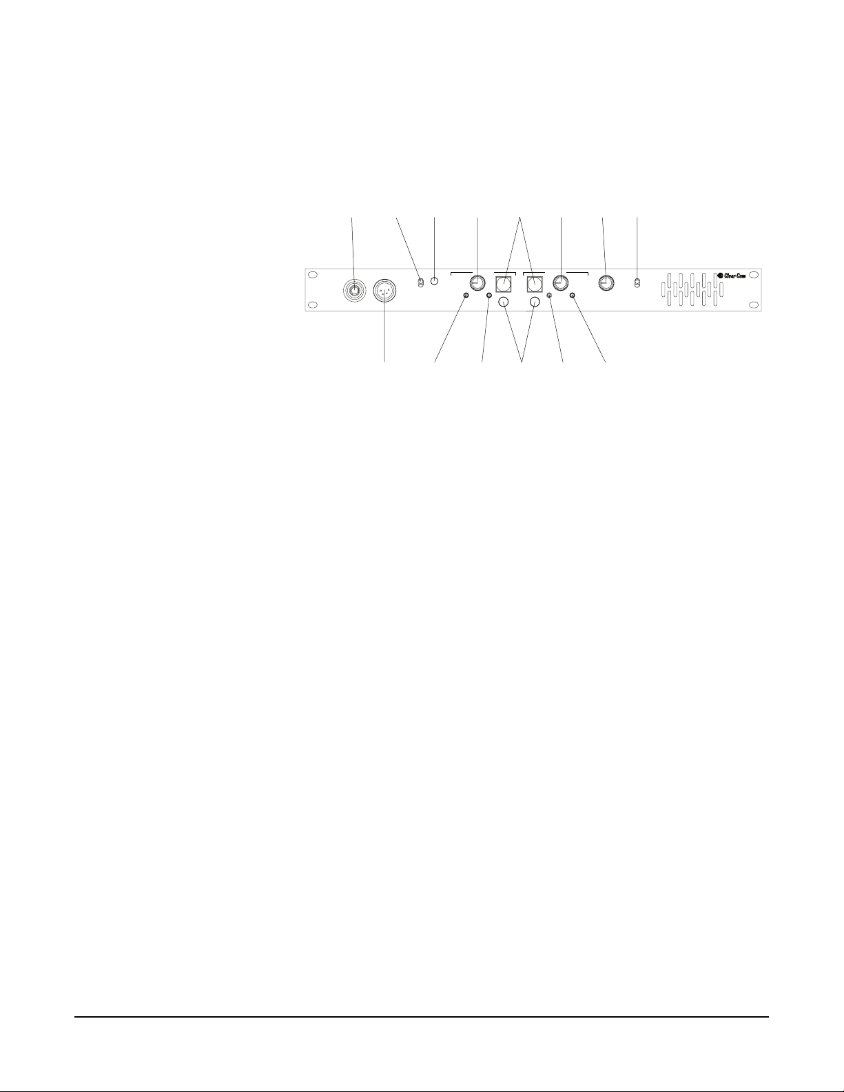
the earphone. If the panel mic and speaker are being used, set the sidetone
control for minimum feed-through to the speaker to prevent feedback.
Panel
Microphone
Panel Mic
MIC
Select
Switch
Headset
Panel
Headset
Announce
Panel Mic
Headset
Program
Button
Announce
Level A
Channel A
Vol ume
Volume
Level
Channel A
Sidetone
Tal k
Buttons
Channel A Channel B
Sidetone
Null
Call
Buttons
Talk
Call
Channel B
Sidetone
Channel B
Sidetone
Vol ume
Null
ProgramProgram
Volum e
Level
Program
Monitor
Level
Program
Level
Program
Level B
Speaker
Switch
On
Off
Speaker
2-Channel
Remote Station
RM-702
Figure 1-1: RM-702 Front Panel
The rest of this section is a detailed description of each control.
TALK BUTTONS
Each channel has its own illuminated talk button for activating the microphone
feed to a given channel. Mechanically, the pushbutton is momentary in action;
however, electrically the button has dual action (momentary or latching)
depending on how the button is pressed. The latching function can be defeated
with a rear-panel DIP switch.
• LATCHING: Pressing the button quickly will toggle the talk function,
alternately turning it on or off.
• MOMENTARY: Pressing the button for longer than 1/4 second will turn
the button press into a momentary function such that when the button is
released the talk function will turn off. In any case the talk function is
activated all of the time the button is pressed.
• TALK INDICATION: The talk button illuminates yellow when a talk is
activated and blue when talk is not active.
• CALL INDICATION: The call button will flash red when a call signal is
received on that channel.
• AUTO-CALL ON TALK: Each channel can be set to send a call signal when
the talk function is active. This function is used to activate IFB circuits or
any other call-activated function available on other stations. A DIP switch
on the rear panel activates this function.
• SPEAKER DIP FUNCTION: Pressing either talk button will reduce the
output level of the speaker by a set amount to avoid feedback.
RM-702 TWO-CHANNEL REMOTE STATION
1-3
Page 10

CALL BUTTONS
Each channel has its own call button. Pressing the call button at any time will
send a call signal on that channel regardless of the activation of the talk circuit for
that channel.
The call button for that channel will flash red while the call button is pressed
indicating the presence of a call signal on the line.
VOLUME CONTROLS
Each channel has a separate volume control for monitoring incoming audio.
Listening is always on and is not controlled by any logic. To listen to a channel,
turn up the appropriate control. To not listen to a channel, turn the control
completely off.
SIDETONE CONTROLS
Each channel has a sidetone null control. This control sets the amount of the
microphone that is heard in the earphone from that channel.
This control is a true hybrid null control and therefore is sensitive to changes in
line loading. For headphone use, it is best to find the null for a given channel and
then rotate the control clockwise to obtain the desired sidetone level.
If the speaker and panel microphone are used together, providing a possible
acoustic feedback path, it will be necessary to use an almost complete null of the
sidetone control.
PROGRAM SEND LEVEL CONTROL FOR CHANNEL A AND B
Both channels A and B have a program send level control that sets the volume of
program audio being sent to that channel when the program is activated.
SPEAKER ON/OFF SWITCH
The switch marked speaker on/off is used to turn the speaker on and off.
MIC SELECT SWITCH
The mic select switch enables the operator to select which microphone is active.
PROGRAM MONITOR LEVEL CONTROL
The program volume control sets the amount of the program signal heard directly
in the headphone or speaker. This control only affects what is heard in the
headphone or speaker and does not affect program feed to the intercom lines.
1-4
RM-702 TWO-CHANNEL REMOTE STATION
Page 11

ANNOUNCE BUTTON
The announce button allows the operator to instantly use the microphone input
to directly talk to a system external to the intercom such as a paging
speaker/amplifier in another room. A dry set of relay contacts on the rear panel is
also available for activating external switching, as needed when the announce
button is pressed.
The button illuminates amber when pressed. Pressing the announce button
momentarily disables any active talks. Active talk circuits will be restored when
the button is released.
The talk-muting action can be defeated if desired by moving an internal jumper.
(See the section on internal options and adjustments.)
RM-702 TWO-CHANNEL REMOTE STATION
1-5
Page 12

1-6
RM-702 TWO-CHANNEL REMOTE STATION
Page 13

2
INSTALLATION
This section discusses the installation of the RM-702 in an intercom system
including typical applications, overall installation theory, detail of each
connector, and adjustments.
INSTALLATION OVERVIEW
This section describes the Clear-Com concept of intercom line connection. The
following subjects are discussed:
• Intercom line connection
• Line termination
• Station powering
• Cable considerations
INTERCOM LINE CONNECTION
The RM-702 provides male and female XLR-3 connectors for each intercom
line, which are looped through.
CONNECTING OR ISOLATING RM-702 CHANNELS
An internal jumper in the RM-702 unit allows you to defeat the power-channel
isolation of the unit, as described in the following procedure.
Note: This adjustment should only be carried out by qualified service personnel.
RM-702 TWO-CHANNEL REMOTE STATION
2-1
Page 14
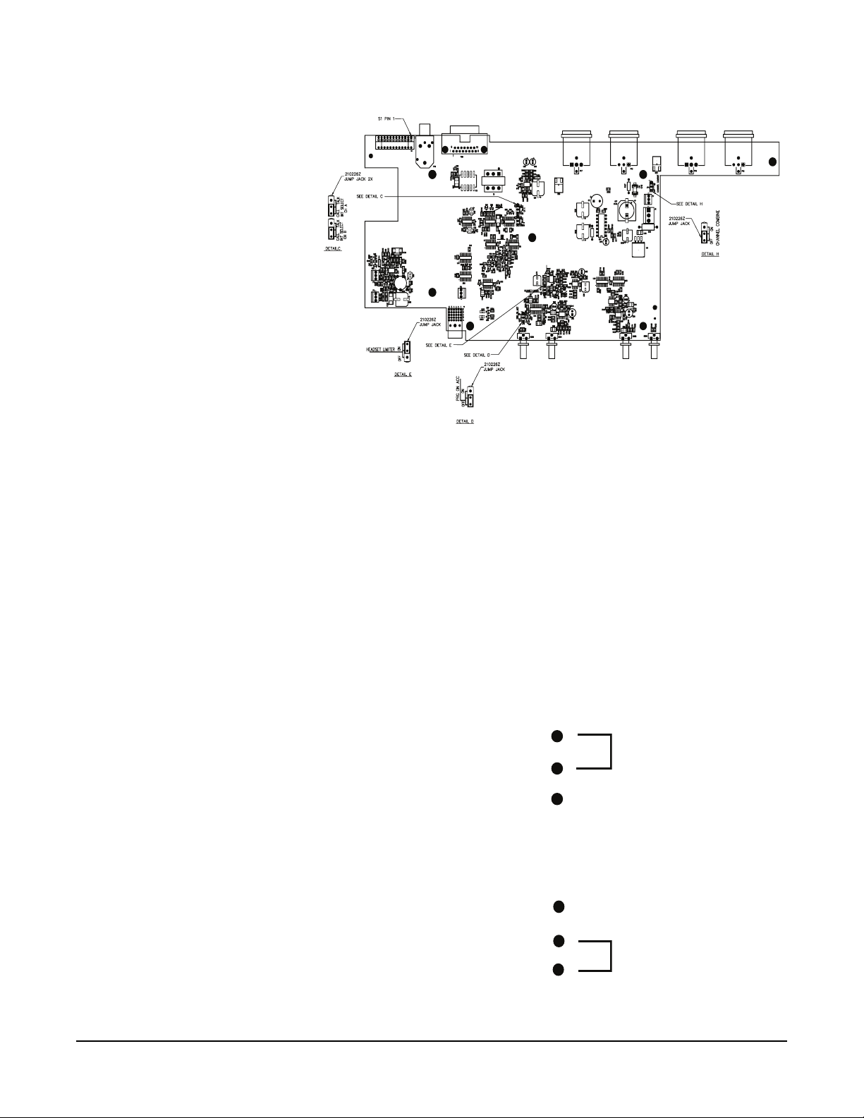
JP5
JP6
JP3
JP2
Figure 2-2: RM-702 PCB Layout
To connect or isolate RM-702 channels:
JP4
1. Please observe anti-static procedures. The circuit cards can be damaged by
static electricity. Please ground yourself and tools before touching any circuit
cards.
2. Remove the cover of the RM-702.
3. On the main circuit board, locate the JP4 three-pin jumper.
The jumper is located on the rightmost upper portion of the circuit card,
when viewed from the front of the unit. The label “J4” appears behind the
jumper. A jumper plug is placed over pins 2 and 3.
2-2
4. Do one of the following:
• To connect the two channels, place the jumper plug over pins 1 and 2.
JP4 1
2
3
Figure 2-3: Jumper Set to Connect Channels
• To isolate the two channels, place the jumper plug over pins 2 and 3.
JP4
1
2
3
Figure 2-4: Jumper Set to Isolate Channels
RM-702 TWO-CHANNEL REMOTE STATION
Page 15

The RM-702 unit is shipped with the jumper plug over pins 2 and 3 to
maintain the power-channel isolation. Power-channel isolation ensures that
if one channel loses power, the other channel will continue to operate.
5. Replace the cover of the RM-702.
LINE TERMINATION
The fundamental concept of Clear-Com party-line intercom is that all stations
provide high-impedance current-sourced signals into a single common system
termination.
The receive or listen section of stations contain a hybrid null circuit that attempts
to reject (null) any talk signal being sent by that station on that channel. The
hybrid null circuit depends on a known impedance on the intercom line to
accomplish this. Variations in impedance on the line upset the null.
CAUTION: All Clear-Com Intercom lines must be terminated. Care must be
taken not to fail to terminate or to “double”-terminate a line. All
unused intercom inputs must be terminated to keep the line drive
circuits stable.
The RM-702 does not provide termination on the intercom line. Clear-Com
main stations and power supplies provide switch-selectable termination networks
on all intercom output lines. It is up to the user to determine where the
termination will be provided. An unterminated line will cause excessive levels,
possible oscillation of line drivers, and severe unbalance of hybrid null networks.
A double- or multiple-terminated line will cause low levels and severe unbalance
of hybrid null circuits.
The termination of an intercom line (or channel) is a 220 Ohm resistor in series
with a 4.7 K Ohm that is paralleled with a 10 uF capacitor.
STATION POWERING
Typical Clear-Com systems are powered by a main station or a power supply.
Clear-Com power supplies can be paralleled to increase the number of remote
stations that can be operated in a system.
CABLE CONSIDERATIONS
The Clear-Com intercom line is intended to run on a shielded twisted pair of
cable per channel of intercom. One conductor carries full duplex (“two-way”)
audio, the other conductor carries the DC power for remote stations. The shield
is used for ground return for audio and power. When choosing interconnect
cable, keep the following considerations in mind:
• DC resistance of the ground or common conductor affects crosstalk. For
runs longer than 500 ft. (152.5 m), do not use wire smaller than 20 gauge.
• The capacitance of the interconnect cable affects system frequency response
and sidetone stability. Total capacitance should not be greater than 0.25 uF.
RM-702 TWO-CHANNEL REMOTE STATION
2-3
Page 16

Portable Installation Cable: Practical cable for portable system interconnections
is flexible, two-conductor, shielded microphone cable. For runs less than 500 ft.
(152.5 m), a cable made of 24-gauge wire is acceptable. For runs longer than
500 ft. (152.5 m), use a 20-gauge cable or larger.
Permanent installation Cable: Vinyl-jacketed shielded pair is the cable of choice
for permanent installations. Use a low-capacitance 20-gauge wire for short runs
of less than 500 ft. (152.5 m) and 18-gauge cable for runs greater than 500 ft.
(152.5 m). Placing the cable in conduit is recommended, but not necessary.
Multi-pair cable that is individually shielded is acceptable for use in
multi-channel systems. For cross-talk considerations, the shields must be tied
together on both ends of the cable to produce the lowest possible DC path for
ground return.
DESCRIPTION OF FRONT PANEL CONNECTORS
HEADSET CONNECTOR (FRONT PANEL)
Note: The following is a description of a recommended headset.
Mic Type --- Dynamic, for details see the technical specifications
Wiring
Pin 1 --- Mic common
Pin 2 --- Mic hot
Pin 3 --- Headphone common
Pin 4 --- Headphone hot
PANEL MIC CONNECTOR (FRONT PANEL)
Clear-Com provides two plug-in panel microphones for use on the RM-702.
The GM-9 is 9 in. (22.86 cm) long and GM-18 is 18 in. (45.72 cm) long. The
microphone is of the electret type. The microphone has a built-in 1/4 in.
(0.64 cm) phone jack for a connector. A mating receptacle is mounted on the
RM-702.
To install a GM-9 or GM-18 panel mount microphone, use the following steps:
1. Check the set screw in the mic-mounting flange to make sure it is clear of the
threads in the bushing.
2. Screw the microphone into the bushing hand-tight.
3. Set the set screw on top of the bushing to lock the mic in place.
2-4
RM-702 TWO-CHANNEL REMOTE STATION
Page 17

DESCRIPTION OF REAR PANEL CONNECTORS
Intercom
Channel
A
Intercom Channel A Intercom Channel BRM-702
Intercom
Channel
B
Accessory
Port
Accessory
Hot Mic/
C-C IFB
System
Hot Mic/
C-C IFB
System
DIP
Switches
A
d B
A
B
B
lk
alk
Feed
alk A
B
a
Fee
alk
nc
On T
Prog
xt IF
On T
Prog
t An
Mom T
t E
Mom T
Call
Call
Intrp
Intrp
Long Line A
Long Line B
Prog
A
Int
Int B
Prog
Off
On
Figure 2-5: RM-702 Rear Panel
INTERCOM LINE CONNECTORS (REAR PANEL, XLR-3 2 MALE & 2 FEMALE)
The RM-702 has a male and female pair of XLR-3 connectors for each intercom
line. The male-female pair of connectors are wired parallel and intended for
loop-through connection.
The pinout of the intercom connectors is as follows:
Pin 1 --- Ground (shield)
Pin 2 --- Power
Pin 3 --- Audio
IFB/HOT MIC (REAR PANEL, 1/4-INCH PHONE JACK)
A 1/4 in. (0.64 cm) phone jack marked IFB/HOT mic provides an output signal
from the selected microphone. This output is intended to work with
Clear-Com’s MA-704 IFB control panel. A control signal into this connector
from the MA-704 causes all active talks from the station to cease and only sends
the IFB output.
The pin description of the connector is as follows:
Tip --- Microphone audio output
Ring --- Control signal (>15 VDC)
Sleeve --- Ground (shield)
RM-702 TWO-CHANNEL REMOTE STATION
2-5
Page 18

ACCESSORY (REAR PANEL, DB-15F)
The accessory DB-15F connector on the rear panel provides program input,
announce audio output, announce relay contacts, and foot switch inputs for
activating a talk on either channel. The pin assignment of the connector is as
follows:
“ACCESSORY” CONNECTOR
DB-15F
1
9
2
10
3
11
4
12
5
13
6
14
7
15
8
Figure 2-6: Viewed from the rear of the connector
Foot Switch Common
Foot Switch “B”
Foot Switch “A”
GND
Announce Relay N.C. Contact
Announce Relay Wiper
Announce Relay N.O. Contact
GND
GND
– Announce Audio Output
+ Announce Audio Output
Power (+30 VDC)
GND
– Program Input
+ Program Input
DESCRIPTION OF OPTIONS AND ADJUSTMENTS
DIP SWITCH OPTION SWITCHES (REAR PANEL)
2-6
Twelve DIP switches on the rear panel enable various options in the station:
• PROGAM ENABLE A: Enables program audio on channel A when set to
the on position.
• PROGRAM ENABLE B: Enables program audio channel B when set to
the on position.
• MOM TALK A: Setting the momentary talk A switch to the on position
will disable the latching function of the channel A talk button. In this
mode, the talk button must always be held in continuously while the
operator is talking on channel A.
• MOM TALK B: Setting the momentary talk B switch to the on position
will disable the latching function of the channel B talk button. In this
mode, the talk button must always be held in continuously while the
operator is talking on channel B.
RM-702 TWO-CHANNEL REMOTE STATION
Page 19

• CALL ON TALK A: If the call on talk A switch is set to the on position, a
call signal will be placed on channel A whenever the talk function is
activated. This can be used to activate any call-activated functions available
on other stations.
• CALL ON TALK B: If the call on talk B switch is set to the on position, a
call signal will be placed on channel B whenever the talk function is
activated. This can be used to activate any call-activated functions available
on other stations.
• INTRPT ANNC: If the interrupt announce switch is set to the on position,
pressing the announce button will disconnect the microphone from the
intercom line(s). This will allow announcements to be made without being
heard over the intercom channels.
• INTRPT EXT IFB: When the hot mic output is connected to Clear-Com’s
IFB system and the interrupt external IFB switch is set to the on position,
pressing a key on the IFB system will disconnect the selected headset or
panel microphone from the intercom line(s). This allows the RM-702
microphone to be used to cue talent without affecting intercom line
communication.
• LONG LINE A: If a long cable run on channel A is unavoidable and
approaches 1,000 ft. (305 m) or more, set the long line A option switch to
the on position. The ability to set a sidetone null on channel A depends
upon properly setting this switch.
• LONG LINE B: If a long cable run on channel B is unavoidable and
approaches 1,000 ft. (305 m) or more, set the long line B option switch to
the on position. The ability to set a sidetone null on channel B depends
upon properly setting this switch.
• PROGRAM INTERRUPT A: Interrupts the program audio to channel A
while a call signal is sent on channel A (default).
You can change this option so that a talk signal, rather than call signal,
interrupts the program audio on channel A. You do this by re-setting an
internal jumper. See the next section, “Re-Setting Program Interrupt
Options,” for instructions.
• PROGRAM INTERRUPT B: Interrupts the program audio to channel B
while a call signal is sent on channel B (default).
You can change this option so that a talk signal, rather than a call signal,
interrupts the program audio on channel B. You do this by re-setting an
internal jumper. See the next section, “Re-Setting Program Interrupt
Options,” for instructions.
The RM-702 is shipped from the factory with all DIP switches in the off
position. To enable a function, place that DIP switch in the on
position.
RM-702 TWO-CHANNEL REMOTE STATION
2-7
Page 20

Momentary Only Talk B
Call-on-Talk A
Interrupt Announce
Program Enable B
Program Enable A
Momentary Only Talk A
Call-on-Talk B
Figure 2-7: DIP switches
Long Line A
Interrupt External IFB
Long Line B
Program Interrupt B
Program Interrupt A
Off (Default)
On
RE-SETTING PROGRAM INTERRUPT OPTIONS
When you set one of the rear-panel program interrupt DIP switches to on for a
particular channel (A or B), any call signal activated on that channel interupts the
program audio during the call signal.
You can change this option so that activating a talk signal, rather than a call
signal, interrupts the program audio for the duration of the signal. You do this by
re-setting an internal jumper on the station’s internal circuit board.
To re-set the program interrupt option:
1. Please observe anti-static procedures. Static electricity can damage a circuit
card. Please ground yourself and tools before touching the circuit card.
2. Remove the cover of the RM-702 by removing the eight Phillips screws.
3. On the main circuit board, locate one of the following:
2-8
• For channel A: The JP5 three-pin jumper, located in the center of the
circuit board.
• For channel B: The JP6 three-pin jumper, located in the center of the
circuit board.
4. A jumper plug covers two of the three pins on each jumper. To change the
program-interrupt option on your station, do one of the following:
• For channel A: Move the jumper plug so that it covers pins 1 and 2. This
causes talk signal activation to interrupt the program audio.
• For channel B: Move the jumper plug so that it covers pins 1 and 2. This
causes talk signal activation to interrupt the program audio.
In the default position, the jumper plug covers pins 2 and 3, which causes
call signal activation, rather than talk signal activation, to interrupt the program audio.
RM-702 TWO-CHANNEL REMOTE STATION
Page 21

JP5, for channel A
T
T
1
2
3
JP6, for channel B
1
2
3
Talk signals
interrupt
program audio
Call signals
interrupt
program audio
FOR EITHER CHANNEL:
o interrupt program audio during talk signals,
place jumper plug over pins 1 and 2.
o interrupt program audio during call signals,
place jumper plug over pins 2 and 3.
Figure 2-8: Changing Program Interrupt Options
PANEL MIC LEVEL ADJUSTMENT (INTERNAL)
The microphone preamplifier for the panel microphone has an internal gain
adjustment control. This gain can be adjusted for different operating conditions.
As shipped from the factory, the control is set to minimum gain such that the
panel microphone and a headset microphone have the same volume when
worked at about 2 in. (5.08 cm).
To adjust the panel microphone gain, you must open the unit. Ground yourself
and tools before touching the circuit board, as circuit boards can be damaged by
static electricity. Remove the top cover of the unit, and locate the jumper labeled
“R161.” It is located on the leftmost side of the circuit board, toward the front of
the unit when facing it. Use a small screwdriver to turn the control clockwise to
increase gain or counterclockwise to decrease gain.
RM-702 TWO-CHANNEL REMOTE STATION
2-9
Page 22
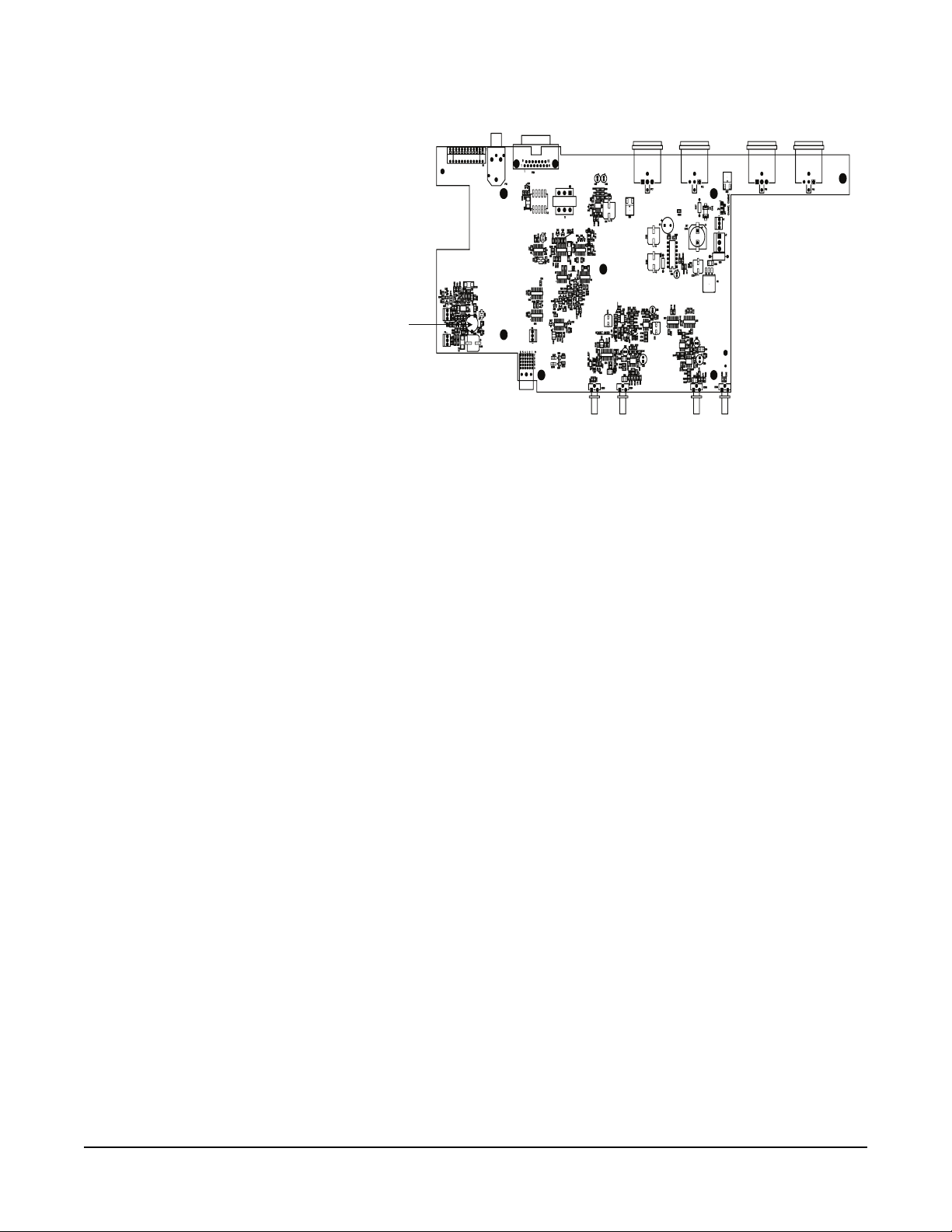
R161
GAIN ADJUST
Figure 2-9: Location of Panel Mic Gain Adjust Control R161
INTERCOM LINE LENGTH COMPENSATION (REAR-PANEL DIP SWITCHES)
The receive circuits of the intercom channels have been optimized for an
intercom line length of up to 1,000 ft. (304.8 m). The capacitance of the
intercom line must be compensated for in the receive circuits if a good sidetone
null is to be achieved. When using a speaker, a good sidetone null is necessary to
achieve a usable listening level.
A set of two rear-panel DIP switches have been provided to compensate for lines
longer than 1,000 ft (304.8 m). Each intercom channel has its own DIP switch.
To change the setting of the line length compensation DIP switches, move either
the long line A or long line B DIP switch to the “on” position for intercom lines
longer than 1,000 ft. (304.8).
PROGRAM FEED ON ANNOUNCE
You can set up the announce feature so that program audio is sent out on the
announce line as well as the announce audio. You set this option up by using an
internal jumper on the circuit board.
To send out program audio along with announcements:
1. Please observe anti-static procedures. Static electricity can damage a circuit
card. Please ground yourself and tools before touching the circuit card.
2. Remove the cover of the RM-702 unit by removing the eight Phillips screws.
3. Locate the JP2 three-pin jumper on the centermost front portion of the circuit
card.
A jumper plug covers pins 2 and 3 of the jumper. This is the off position.
4. Remove the jumper plug from the pins and place it over pins 1 and 2. This is
the on position.
2-10
Program audio will now accompany the announce audio.
RM-702 TWO-CHANNEL REMOTE STATION
Page 23

TYPICAL SYSTEM APPLICATIONS
ENG/EFP TRUCK
The following block diagram describes a typical ENG/EFP truck installation.
Director
Engineer
Telephone Interface
RM-702
Program Input
Assistant Director/
Floor Manager
RS-601
AC-701
Telc o
Line
Power Supply
PS-702
RM-702
Channel A
Channel B
Camera
Operator
RS-601
Talent Announcer
TR-50
Figure 2-10: Typical ENG/EFP Truck Installation
The system has two 2-channel RM-702 rack-mount stations. The system is
powered from a Clear-Com power supply that also provides the terminations for
both channels.
Channel B is connected to talent receivers for announcers.
A telephone line interface is connected to the program input of station #2. It
provides a program feed from the studio via a dial-up telephone line. Its
DIP switch options are set to insert program audio on channel B and interrupt
the program when a call signal is present on channel B. The option DIP switches
for placing a call signal on channel B is set on both RM-702s. Now, whenever
either RM-702 initiates a talk to the announcers, it interrupts the program feed
(to the announcers).
RM-702 TWO-CHANNEL REMOTE STATION
2-11
Page 24

CABLE/SCHOOL TELEVISION STUDIO
The following block diagram describes a typical cable or school television studio
installation.
Director
RM-702
Assistant Director
RM-702
Video
Graphics
HB-702HB-702
PS-702
Program Input
From station PA outputs
Provided by user
Mixer/Amp
Paging spkr
in studio
Channel A
Tale nt
Channel B
C,ameras Floor Managers
RS-601
TR-50
RS-601 RS-601
Announcer
TR-50
RS-601 RS-601
Figure 2-11: Typical Cable or School Television Studio Installation
The system has several 2-channel RM-702 rack mount stations and several wall
mount 2-channel stations. The system is powered from a Clear-Com power
supply that also provides the terminations for both channels.
A line of single-channel beltpacks is connected to channel A. The beltpacks are
used for the cameras and floor managers. Normal communication between all
parties is on channel A.
Channel B is connected to talent receivers for announcers. The program that is
to feed the announcers is connected to the first RM-702. Its DIP switch options
are set to insert program on channel B and interrupt the program when a call
signal is present on channel B. The option DIP switches for placing a call signal
on channel B is set on both RM-702s. Now, either RM-702 will interrupt the
program feed to the announcer when a talk is initiated from it to the announcers.
2-12
A PA amplifier is connected to the announce output of the first RM-702 such
that the operator of that station could talk directly to everyone in the studio.
ACTUAL APPLICATIONS
This section describes detailed instructions for various types of applications. A
block diagram such as those in the previous section describing an ENG/EFP
truck and a cable/school television studio should be developed for your
application. The following sub-topics in this section describe in detail each of the
major application types that might be encountered. The sub-topics in this
section are:
• Intercom line wiring
•Program input
• Internal IFB operation
• External IFB (MA-704 and PIC-4704 connections)
• PA feed to studio output
RM-702 TWO-CHANNEL REMOTE STATION
Page 25

• Remote control of talk switches
• Inadequate sidetone adjustment
INTERCOM LINE WIRING
The intercom line wiring has several purposes in the Clear-Com system:
• Connection of the audio intercom signal between stations.
• Delivery of DC power for remote stations (such as the RM-702) to operate
from.
• Termination of the intercom audio line external to remote stations.
Connect the intercom lines of stations and power supplies using a shielded
twisted pair cable with XLR 3-pin connectors (the same as used for balanced
microphones). Refer to the installation overview section of this manual for more
information.
The RM-702 has a male and female pair of XLR-3 connectors for each intercom
line. The male-female pair of connectors are wired parallel and intended for
loop-through connection.
The pinout of the intercom connectors are as follows:
Pin 1 --- Ground (shield)
Pin 2 --- Power
Pin 3 --- Audio
The following application shows the practical connection of the intercom lines in
the block diagram of the cable/school television studio.
Assistant
4
C
15
B
To
Headset
To
Ear Piece
Director
RM-704
BA
B
A
3
3
3
Cameras
RS-601 RS-601
4
33
To
Headset
Announcer
C
3
To
Ear Piece
Video Graphics
HB-702
4
3
To headset
3
3
H
H
RS-601 RS-601
4
Connection Codes
03 = 3-pin “xlr”
04 = 4-pin “xlr”
15 = DB-15
B = 1/4-inch stereo phone plug (ring/tip/sleeve)
C = 1/8-inch mono phone plug (tip/sleeve)
H = Screw terminals
W = AC power cord
To
Headset
Male
3
Female
3
HB-702
4
H
H
To
headset
Floor Managers
4
3
To
Headset
4
4
To headset
To
Headset
A
PS-702
B
Program Input
From station SA outputs
Provided by user
Mixer/Amp
Paging
Speaker
Director
RM-704
B
3
3
3
3
3
3
3
A
B
A
4
3
3
Channel A
Channel B
To headset
RS-601
3
3
Tal ent
3
Figure 2-12: Connecting a Small Cable/School Television Studio
The entire system is wired using male/female microphone cables looped-through
each station except for the HB-702s. The HB-702 has screw terminals for the
intercom lines. The PS-702 provides the DC power for the system and the line
termination switches must be turned on.
RM-702 TWO-CHANNEL REMOTE STATION
2-13
Page 26

CAUTION: All Clear-Com Intercom lines must be terminated. Care must be
taken not to fail to terminate or to “double”-terminate a line. All
unused intercom inputs must be terminated to keep the line drive
circuits stable. The RM-702 does not provide termination on the
intercom line.
PROGRAM INPUT
There are two different purposes for the program input: monitoring program in
the speaker and headphone, or feeding the Channel A and B intercom lines with
program material.
• Monitoring Program: To monitor program in the headphone or speaker:
• Connect the program source to the proper pins on the DB-15.
• Make sure the appropriate rear-panel program enable DIP switch is set to
the on position. For channel A, set the program enable A DIP switch to on.
For channel B, set the program enable B DIP switch to on.
• Use the large knob labeled “Program Volume,” located right next to the
speaker on/off switch, to set the appropriate program volume level. This
knob controls the program volume in the speaker/headphone.
• Set either the A or B potentiometer marked Program Level, located under
either the A or B channel’s volume knob, to the lowest setting. This control
affects the program volume going out onto the selected intercom line.
• Feeding Channel A or B Intercom Line: To feed the A or B channel with
program material:
• Connect the program source to the proper pins on the DB-15.
• Make sure the appropriate (A or B) rear-panel program enable DIP switch is
set to the on position. For channel A, set the program enable A DIP switch
to on. For channel B, set the program enable B DIP switch to on.
• Set the large knob, labeled “Program Volume,” located right next to the
speaker on/off switch, to the appropriate level. This knob controls the
program volume in the speaker/headphone.
• Set either the A or B potentiometer marked Program Level, located under
either the A or B channel’s volume knob, to the desired level. This control
affects the program audio level on the intercom line.
• If it is desired to interrupt this program feed, set the appropriate (A or B)
rear-panel Program Interrupt DIP switch to on and ensure that the Program
Enable DIP switch for the channel is set to off. When you do so, any time
you activate a call signal, the program audio is interrupted for the duration
of the call signal. There is an option to change this so that any time you
activate a talk signal, the program audio is interrupted for the duration of
the talk signal. See the earlier section in this chapter, “Re-setting Program
Interrupt Options,” for more information on setting this option.
2-14
RM-702 TWO-CHANNEL REMOTE STATION
Page 27
• To Connect To The Program Input: The program input of the RM-702 is
available in the DB-15 accessory connector on the rear panel.
“ACCESSORY” CONNECTOR
DB-15F
1
9
2
10
3
4
5
6
7
8
11
12
13
14
15
Viewed from the
rear of the unit
Power (+30 VDC)
GND
– Program Input
+ Program Input
Figure 2-13: Connecting Program Sources
Connect a balanced input to pins #8 and #15 with the shield connected to
pin #7.
To connect an unbalanced input, connect the signal to pin #8 and connect the
shield to pins #15 and #7.
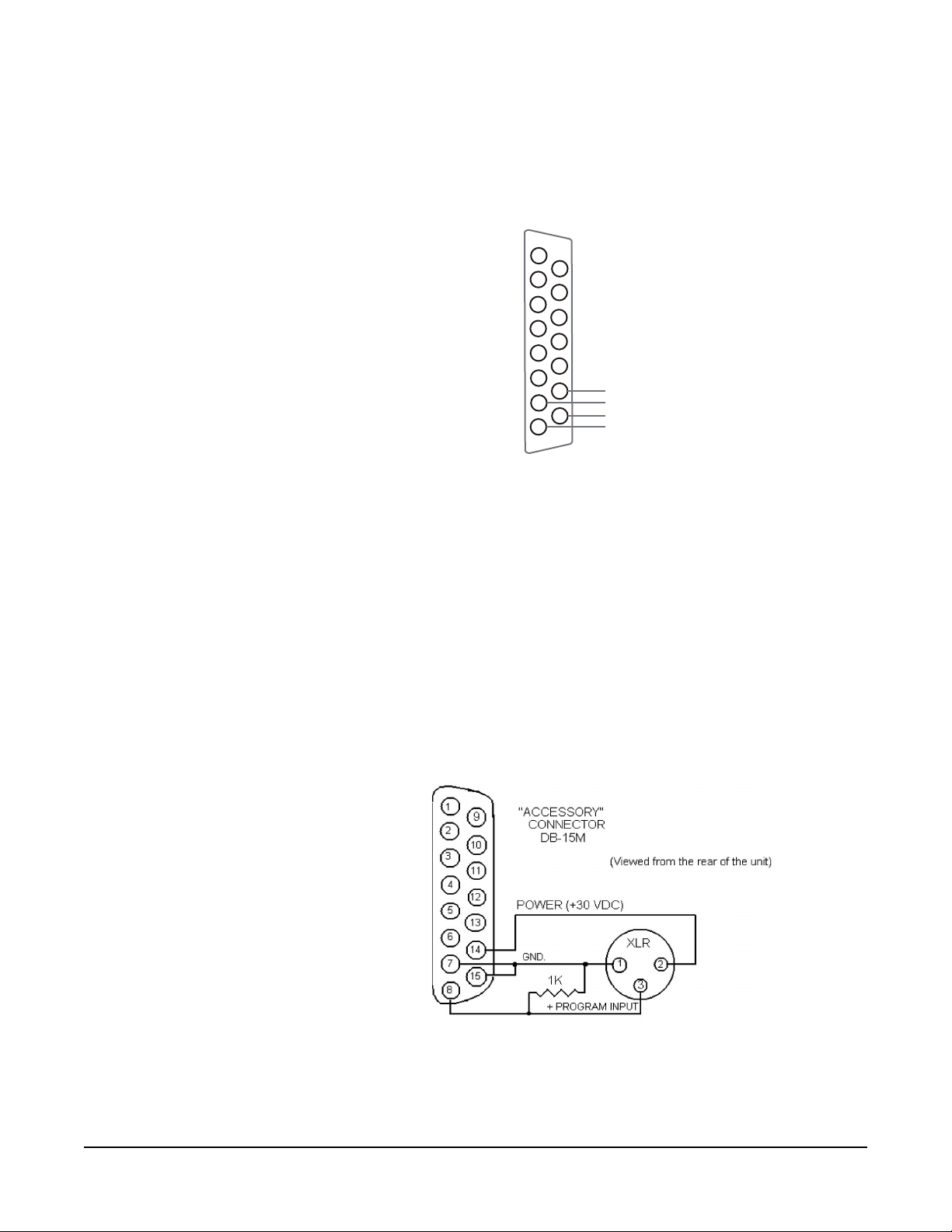
Connecting Party-Line Products As Program Sources: If other Clear-Com
products (such as an AC-701 telephone interface) are to be used as a program
source directly, use the following interconnection cable.
Pin #14 of the DB-15 accessory connector provides +30 VDC to power the
external device. Connecting pins #7 and #15 together unbalances the program
input. The output from the party line device is connected to pin #8 with a
1KOhm load to provide a partial termination.
RM-702 TWO-CHANNEL REMOTE STATION
Figure 2-14: Connecting Party-Line Products As Program Sources
2-15
Page 28

INTERNAL IFB OPERATION
To use either channel A or B as an IFB feed, connect the program source to the
program input (as described in the previous section) and set the Program
Interrupt A (or B) DIP switch to the on position. The program will now be
interrupted whenever there is a call signal present on channel B. If there are
multiple RM-702s in the system, the program should only be fed into one of the
RM-702s.
To interrupt the IFB program automatically when a talk rather than a call signal
is active on channels A or B, you must reset an internal jumper as described in
“Re-Setting Program Interrupt Options” earlier in this chapter.
EXTERNAL IFB (MA-704 AND PIC-4704 CONNECTION)
Clear-Com provides a stand-alone IFB system called a PIC-4704. The PIC-4704
provides four interruptible IFB feeds from two program sources, and is located in
a central location. The MA-704 is a four-channel control head intended to work
with the PIC-4704. An MA-704 is located at each location where program
interrupt is to be initiated. Each MA-704 has its own panel-mounted
microphone which, when mounted next to an intercom station with a panel
mounted microphone, causes panel congestion with two microphones at a single
location.
The RM-702 has a 1/4 in. (0.64 cm) phone jack output on its rear panel
intended to connect directly to an MA-704 and provide a microphone feed to
the MA-704. The MA-704 can be ordered without a panel-mounted
microphone. When a button is pressed on the MA-704, a control signal will
temporarily transfer the microphone in use on the RM-702 to the MA-704,
muting any talks active on the RM-702.
To connect the RM-702 to an MA-704, use a two-wire shielded cable with
1/4 in. (0.64 cm) tip, ring, and sleeve jacks on each end. Connect the tip to the
tip, the ring to the ring, and use the shield to connect the sleeve to the sleeve.
1/4” phone jack
Channel A
Channel B
Power
Supply
PS-702
1/4” phone jack
Figure 2-15: Typical External IFB System Using a PIC-4704 and MA-704 with a RM-702
Director
RM-702
Assistant
Director
RM-702
To additional party line
Stand-alone
IFB system
PGM 1
PGM 2
PIC-4704
2-16
RM-702 TWO-CHANNEL REMOTE STATION
Page 29

PA FEED TO STUDIO OUTPUT
Pressing the button marked announce on the front of the RM-702 temporarily
disables activity of the station and places the output of the selected microphone
on the announce audio output terminals of the accessory I/O DB-15 connector on
the rear panel of the station. Isolated relay contacts are also available for
controlling some external devices, such as a PA amplifier to another room.
To connect to the announce output, connect a shielded twisted-pair cable to pins
#6 and #13 of the accessory connector and use pin #5 for connection of the
shield.
A relay is provided that activates when the announce button is pressed and its
contacts are available on the accessory connector. The relay is rated for 2.0 Amps
of DC current at 24 VDC.
RM-702 TWO-CHANNEL REMOTE STATION
Figure 2-16: Connections for Announce Audio and Relay Outputs
2-17
Page 30

REMOTE CONTROL OF TALK SWITCHES
The talk switches of the RM-702 can be remotely controlled with external
contacts that are available on the accessory connector on the rear panel. A
footswitch or remote pushbutton when wired to the accessory connector acts
exactly the same as pushing a talk switch on the front panel. Both latching and
momentary actions are active.
Figure 2-17: Connection of External Talk Switches
INADEQUATE SIDE-TONE ADJUSTMENT
The receive circuits of the intercom channels have been optimized for an
intercom line length of up to 1,000 ft (305 m). The capacitance of the intercom
line must be compensated for in the receive circuits if a good sidetone null is to
be achieved. When using a speaker, a good sidetone null is necessary to achieve a
usable listening level.
Two rear-panel DIP switches are provided to compensate for lines longer than
1,000 ft. (305 m). Each intercom channel has its own DIP switch, as described
in “DIP Switch Option Switches” earlier in this chapter.
2-18
RM-702 TWO-CHANNEL REMOTE STATION
Page 31
MAINTENANCE
3
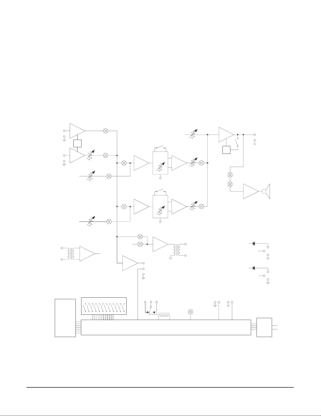
INTRODUCTION
This chapter provides maintenance information.
M-702
Headset
Mic
XLR4
Mic
Limiter
Panel
Mic
Jack
Main
Pgm
Panel Mic
Gain
Program
Level A
Line
Length
Line
Length
Sidetone
Null
Intercom
Line A
Sidetone
Null
Main
Pgm
Program
Level
Listen
A
Headset
Limiter
Spkr
On/Off
Mute
Headset
XLR4
3
Main
Pgm
2
Front Panel
Switches,
Buttons, &
Indicators
Main
Pgm
Program
Level B
Option Switches
Intercom
Line B
Main
Pgm
Main
Pgm
Hot Mic /
IFB Out
Annc Rly
Control
To All
Switches
System Logic
Figure 3-18: Audio Block Diagram for the RM-702
Listen
B
3
SA
Output
2
Footswitches
A
B
+30VDC
+30VDC
Intercom
Line A
Intercom
Line B
Power A
Power B
Call
Signal
Send &
Receive
3
3
2
Channel A
1
2
Channel B
1
XLRs (2)
XLRs (2)
A
Intercom
B
Lines
RM-702 TWO-CHANNEL REMOTE STATION
3-1
Page 32

3-2
RM-702 TWO-CHANNEL REMOTE STATION
Page 33

4
TECHNICAL SPECIFICATIONS
RM-702 TWO-CHANNEL STATION
dBu is an absolute measurement. 0 dBu is referenced to 0.775 volts RMS
Panel Microphone Input
Input Type Electret
Input Impedance >=2K
Mic Limiter Threshold 0dBu ±3dB
Mic Limiter Range >= 20dB
Headset Microphone Input
Input Type Dynamic
Input Impedance >= 1K
Mic Limiter Threshold 0dBu ± 3dB
Mic Limiter Range >= 15dB
Program Line Input
Maximum Level before Clipping >= 20dBu
Input Impedance >= 5K
Ω
Ω
Ω
Headset Output
Load Impedance >= 8
Output Impedance <= 25
Output Limiter Threshold +5dBu ± 3dB
Maximum Output Level before Distortion >= 17dBu
Speaker Output
Load Impedance >= 4
Max Output Level before 1% Distortion 20dBu ± 2dBu
Party Line Output
Off Noise < -74dBu
Output Impedance >10K
Party Line Input
Crosstalk < -60dB
Max level before Clipping >= 12dBu
Sidetone Null Capability > 25dB
Stage Announce/Balanced Line Out
Ty p e B al a nc e d
Output Impedance >= 200
Load Impedance >= 600
Ω
Ω
Ω
Ω
Ω
Ω
RM-702 TWO-CHANNEL REMOTE STATION
4-1
Page 34

IFB/Hot Mic
Ty p e U nb a l a nc ed
Output Impedance 180
Load Impedance >= 600
Ω
Ω
Frequency Response
Panel Mic - Party Line 600 - 10KHz ± 3dB
Headset Mic - Party Line 200 - 12KHz ± 3dB
Headset Mic - Line Out 200 - 12KHz ± 3dB
Program Input - Party Line 100 - 17KHz ± 3dB
Program Input - Headset Out 200 - 10KHz ± 3dB
Program Input - Speaker Out 300 - 10KHz ± 3dB
Party Line - Headset Out 200 - 10KHz ± 3dB
Party Line - Speaker Out 300 - 10KHz ± 3dB
Max Distortion
Panel Mic - Party Line <= 0.5%
Headset Mic - Party Line <= 0.5%
Headset Mic - Line Out <= 0.5%
Program Input - Party Line <= 0.2%
Program Input - Headset Out <= 0.2%
Program Input - Speaker Out <= 0.5%
Party Line - Headset Out <= 0.2%
Party Line - Speaker Out <= 0.5%
Noise
Panel Mic - Party Line < -65dBu
Headset Mic - Party Line < -70dBu
Headset Mic - Line Out < -55dBu
Program Input - Party Line < -85dBu
Program Input - Headset Out < -60dBu
Program Input - Speaker Out < -60dBu
Party Line - Headset Out < -50dBu
Party Line - Speaker Out < -50dBu
Max Gain
Panel Mic - Party Line >= 37dB
Headset Mic - Party Line 41dB ± 2dB
Headset Mic - Hot Mic Out 55dB ± 3dB
Headset Mic - Announce Out 55dB ± 3dB
Program Input - Party Line >= -16dB
Program Input - Headset Out >= 18dB
Program Input - Speaker Out >= 24dB
Party Line - Headset Out >= 34dB
Party Line - Speaker Out >= 40dB
Min Gain
Panel Mic - Party Line <= 25dB
4-2
RM-702 TWO-CHANNEL REMOTE STATION
Page 35

Power
Input Voltage Range 20-30 VDC
Input Current (Idle) <= 90mA
Input Current (Max) <=110mA
Rear Panel Connectors
Intercom: (2) XLR-3M (1 per channel)
(2) XLR-3F (1 per channel)
Hot Mic / IFB Interface: (1) 1/4 in. (0.64 cm) phone jack
Accessory (1) DB-15F
Rear Panel Controls
(12) Option switches
Front Panel Connectors
Panel Mic: (1) 1/4 in. (0.64 cm) panel
mounting jack
Headset: (1) XLR-4M
Front Panel Controls & Indicators
(1) Panel / headset mic switch
(1) Announce button
(2) Program send level controls
(1) Program monitor level control
(2) Listen controls
(2) Sidetone null controls
(2) Talk buttons
(2) Call buttons
(1) Speaker ON-OFF switch
Environmental
Dimensions
Dimensions: 19 in. W x 1.75 in. H x 7.0 in. D
Weight
Weight: 5.2 lbs. (2.36 Kg)
Notice About Specifications
While Clear-Com makes every attempt to maintain the accuracy of the
information contained in its product manuals, that information is subject to
change without notice. Performance specifications included in this manual are
design-center specifications and are included for customer guidance and to
facilitate system installation. Actual operating performance may vary.
RM-702 TWO-CHANNEL REMOTE STATION
32 - 122o F (0 - 50o C)
(483 mm x 44.5 mm x 178 mm)
4-3
Page 36

4-4
RM-702 TWO-CHANNEL REMOTE STATION
Page 37

VGC offers 24 x 7 customer
support if you have an
Extended Warranty or
Service Contract.
Return Material
Authorization (RMA)
numbers are required for all
returns.
LIMITED WARRANTY
Vitec Group Communications (VGC) warrants that at the time of purchase, the
equipment supplied complies with any specification in the order confirmation
when used under normal conditions, and is free from defects in workmanship
and materials during the warranty period.
During the warranty period VGC, or any service company authorized by VGC,
will in a commercially reasonable time remedy defects in materials, design, and
workmanship free of charge by repairing, or should VGC in its discretion deem it
necessary, replacing the product in accordance with this limited warranty. In no
event will VGC be responsible for incidental, consequential, or special loss or
damage, however caused.
WARRANTY PERIOD
The product may consist of several parts, each covered by a different warranty
period. The warranty periods are:
• Cables, accessories, components, and consumable items have a limited
warranty of 90 days.
Both warranty and
non-warranty repairs are
available.
• Headsets, handsets, microphones, and spare parts have a limited warranty of
one year.
• UHF wireless IFB products have a limited warranty of one year.
• UHF wireless intercom systems have a limited warranty of three years.
• All other Clear-Com and Drake brand systems and products, including
beltpacks, have a limited warranty of two years.
The warranty starts at the time of the product’s original purchase. The warranty
start date for contracts which include installation and commissioning will
commence from the earlier of date of the Site Acceptance Test or three months
from purchase.
TECHNICAL SUPPORT
To ensure complete and timely support to its customers, VGC’s User Support
Center is staffed by qualified technical personnel. Telephone and email technical
support is offered worldwide by the User Support Center.
The User Support Center is available to VGC’s customers during the full course
of their warranty period. Telephone support during the warranty period will be
offered at no charge between 09:00 and 17:00 according to the customer’s local
time zone.
In addition, for customers who purchase an Extended Warranty or Service
Contract, 24-hour customer support is offered immediately upon purchase of
WARRANTY
i
Page 38

such agreement. For more information, contact your authorized dealer,
distributor, or sales representative.
Instructions for reaching VGC’s User Support Centers are given below.
Telephone for Europe, Middle East and Africa: +49 40 6688 4040
Telephone for the Americas and Asia: +1 510 337 6600
Email: vitec.support@AVC.de
Once the standard warranty period has expired, the User Support Center will
continue to provide telephone support if you have purchased an Extended
Warranty or Service Contract. In these cases, you will have access to telephone
support 24 hours per day, 7 days per week.
WARRANTY REPAIRS AND RETURNS
Before returning equipment for repair, contact a User Support Center to obtain a
Return Material Authorization (RMA). VGC representatives will give you
instructions and addresses for returning your equipment. You must ship the
equipment at your expense, and the support center will return the equipment at
VGC’s expense.
For out-of-box failures, use the following contact information:
Europe, Middle East and Africa
Tel: +44 1223 815000 Email: customerservicesEMEA@vitecgroup.com
North America, Canada, Mexico, Caribbean & US Military
Tel: +1 510 337 6600 Email: customerservicesUS@vitecgroup.com
Asia Pacific & South America
Tel: +1 510 337 6600 Email: customerservicesAPAC@vitecgroup.com
VGC has the right to inspect the equipment and/or installation or relevant
packaging.
NON-WARRANTY REPAIRS AND RETURNS
For items not under warranty, you must obtain an RMA by contacting the User
Support Center. VGC representatives will give you instructions and addresses for
returning your equipment.
You must pay all charges to have the equipment shipped to the support center
and returned to you, in addition to the costs of the repair.
EXTENDED WARRANTY
ii
If you purchase an Extended Warranty, you are also given access free of charge to
the User Support Center 24 hours a day, 7 days a week.
You can purchase an extended warranty at any time during the first two years of
ownership of the product. The purchase of an extended warranty extends to five
WARRANTY
Page 39

years the warranty of any product offered with a standard two-year warranty.
The total warranty period will not extend beyond five years. Any purchase of an
extended warranty provides 24 x 7 customer support in addition to the warranty
immediately upon purchase of the warranty extension.
Note: VGC does not offer warranty extensions on UHF wireless intercom
systems, or on any product with a 1-year or 90-day warranty.
SERVICE CONTRACT
VGC also offers service contracts that provide 24 x 7 telephone support, advance
replacements, training, proactive maintenance, on-site visits, and no charge for
repair or replacement of equipment. For more information, contact your
authorized dealer, distributor, or sales representative.
LIABILITY
THE FOREGOING WARRANTY IS VGC'S SOLE AND EXCLUSIVE
WARRANTY. THE IMPLIED WARRANTY OF MERCHANTABILITY
AND FITNESS FOR A PARTICULAR PURPOSE AND ANY OTHER
REQUIRED IMPLIED WARRANTY SHALL EXPIRE AT THE END OF
THE WARRANTY PERIOD. THERE ARE NO OTHER WARRANTIES
(INCLUDING WITHOUT LIMITATION WARRANTIES FOR
CONSUMABLES AND OTHER SUPPLIES) OF ANY NATURE
WHATSOEVER, WHETHER ARISING IN CONTRACT, TORT,
NEGLIGENCE OF ANY DEGREE, STRICT LIABILITY OR OTHERWISE,
WITH RESPECT TO THE PRODUCTS OR ANY PART THEREOF
DELIVERED HEREUNDER, OR FOR ANY DAMAGES AND/OR LOSSES
(INCLUDING LOSS OF USE, REVENUE, AND/OR PROFITS). SOME
STATES DO NOT ALLOW THE EXCLUSION OR LIMITATION OF
INCIDENTAL OR CONSEQUENTIAL DAMAGES OR THE
LIMITATION ON HOW LONG AN IMPLIED WARRANTY LASTS, SO
THE ABOVE LIMITATIONS MAY NOT APPLY TO YOU. IN ANY
EVENT, TO THE MAXIMUM EXTENT PERMITTED UNDER
APPLICABLE LAW, VGC'S LIABILITY TO CUSTOMER HEREUNDER
SHALL NOT UNDER ANY CIRCUMSTANCES EXCEED THE COST OF
REPAIRING OR REPLACING ANY PART(S) FOUND TO BE
DEFECTIVE WITHIN THE WARRANTY PERIOD AS AFORESAID.
This warranty does not cover any damage to a product resulting from cause other
than part defect and malfunction. The VGC warranty does not cover any defect,
malfunction, or failure caused beyond the control of VGC, including
unreasonable or negligent operation, abuse, accident, failure to follow
instructions in the manual, defective or improperly associated equipment,
attempts at modification and repair not approved by VGC, and shipping
damage. Products with their serial numbers removed or defaced are not covered
by this warranty.
This warranty does not include defects arising from installation (when not
performed by VGC), lightning, power outages and fluctuations, air conditioning
failure, improper integration with non-approved components, defects or failures
WARRANTY
iii
Page 40

of customer furnished components resulting in damage to VGC provided
product.
This limited warranty is not transferable and cannot be enforced by anyone other
than the original consumer purchaser.
This warranty gives you specific legal rights and you may have other rights which
vary from country to country.
iv
WARRANTY
 Loading...