

Page 1

CLEAR-COM WIRELESS IFB
PRC-2
UHF MULTI-FREQUENCY BELT-PACK IFB
RECEIVER
INSTRUCTION MANUAL
Page 2

PRC-2 UHF Multi-Frequency Belt-Pack IFB Receiver Instruction Manual
© 2008 Vitec Group Communications Ltd. All rights reserved.
Part Number 810400Z Rev. 2
Vitec Group Communications LLC
850 Marina Village Parkway
Alameda, CA 94501
U.S.A
Vitec Group Communications Ltd
7400 Beach Drive
IQ Cambridge
Cambridgeshire
United Kingdom
CB25 9TP
Vitec Group Communications
Room 1806, Hua Bin Building
No. 8 Yong An Dong Li
Jian Guo Men Wai Ave
Chao Yang District
Beijing, P.R. China 100022
® Clear-Com, CellCom/FreeSpeak and the Clear-Com Communication Systems logo are registered trademarks of The Vitec Group plc.
Page 3

CONTENTS
INTRODUCTION . . . . . . . . . . . . . . . . . . . . . . . . . . . 1-1
Introduction. . . . . . . . . . . . . . . . . . . . . . . . . . . . . . . . . . . . . . . . . . . .1-1
General Technical Description . . . . . . . . . . . . . . . . . . . . . . . . . . . . .1-1
General Features . . . . . . . . . . . . . . . . . . . . . . . . . . . . . . . . . . . . . . .1-2
Control Knob. . . . . . . . . . . . . . . . . . . . . . . . . . . . . . . . . . . . . . . . .1-2
LED Indicator . . . . . . . . . . . . . . . . . . . . . . . . . . . . . . . . . . . . . . . .1-3
Headphone Jack. . . . . . . . . . . . . . . . . . . . . . . . . . . . . . . . . . . . . .1-3
Mono Plug/Stereo Plug Usage . . . . . . . . . . . . . . . . . . . . . . . . . . .1-4
Audio Level . . . . . . . . . . . . . . . . . . . . . . . . . . . . . . . . . . . . . . . . . .1-4
Frequency Adjustment . . . . . . . . . . . . . . . . . . . . . . . . . . . . . . . . .1-4
Receiver Operating Instructions . . . . . . . . . . . . . . . . . . . . . . . . . . . .1-6
Receiver Normal Operation (already programmed) . . . . . . . . . . .1-6
Programming- Add a New Frequency To the Next Open Channel1-6
Erase All 5 Channel Memories . . . . . . . . . . . . . . . . . . . . . . . . . . .1-7
Multiple Transmitter Setup . . . . . . . . . . . . . . . . . . . . . . . . . . . . . .1-7
Battery Instructions . . . . . . . . . . . . . . . . . . . . . . . . . . . . . . . . . . . .1-8
Troubleshooting . . . . . . . . . . . . . . . . . . . . . . . . . . . . . . . . . . . . . . .1-10
SPECIFICATIONS. . . . . . . . . . . . . . . . . . . . . . . . . . 2-1
LIMITED WARRANTY. . . . . . . . . . . . . . . . . . . . . . . W-I
Warranty Period . . . . . . . . . . . . . . . . . . . . . . . . . . . . . . . . . . . . . . . .W-i
Technical Support. . . . . . . . . . . . . . . . . . . . . . . . . . . . . . . . . . . . . . .W-i
Warranty Repairs and Returns . . . . . . . . . . . . . . . . . . . . . . . . . . . . W-ii
Non-Warranty Repairs and Returns . . . . . . . . . . . . . . . . . . . . . . . . W-ii
Extended Warranty. . . . . . . . . . . . . . . . . . . . . . . . . . . . . . . . . . . . . W-ii
Liability . . . . . . . . . . . . . . . . . . . . . . . . . . . . . . . . . . . . . . . . . . . . . .W-iii
Vitec Group Communications
PRC-2 UHF Multi-Frequency Belt-Pack IFB Receiver
i
Page 4

ii
PRC-2 UHF Multi-Frequency Belt-Pack IFB Receiver
Vitec Group Communications
Page 5

Please read and follow these
instructions before operating
this product.
IMPORTANT SAFETY INSTRUCTIONS
1. Read these instructions.
2. Keep these instructions.
3. Heed all warnings.
4. Follow all instructions.
5. Do not use this apparatus near water.
6. Clean only with dry cloth.
7. Do not block any ventilation openings. Install in accordan ce with the
manufacturer’s instructions.
8. Do not install near any heat sources such as radiators, heat
registers, stoves, or other apparatus (including amplifiers) that
produce heat.
9. Only use attachments/accessories specified by the manufacturer.
10. Use only with the cart, stand, tripod, bracket, or table specified by
the manufacturer, or sold with the apparatus. When a cart is used,
use caution when moving the cart/apparatus combination to avoid
injury from tip-over.
11. Unplug this apparatus during lightning storms or when unused for
long periods of time.
12. Refer all servicing to qualified service personnel. Servicing is
required when the apparatus has been damaged in any way, such
as power-supply cord or plug is damaged, liquid has been spilled or
objects have fallen into the apparatus, the apparatus has been
exposed to rain or moisture, does not operate normally, or has been
dropped.
13. WARNING: To reduce the risk of fire or electric shock, do not
expose this product to rain or moisture.
SAFETY NOTES
Excessive sound levels can cause permanent hearing damage.
1. Always adjust the volume to the lowest level before listening to
unknown transmissions.
2. Use the lowest reasonable level consistent with hearing safety.
3. Do not use high sound levels in the earphone to overcome high
ambient sound levels. That is absolutely foolish! Demand and use
high isolation earphones.
4. Do not expose your ears to sound levels that cause them to ring. If
your ears do ring after exposure, think of it as a warning bell telling
you not to do that again.
Vitec Group Communications
PRC-2 UHF Multi-Frequency Belt-Pack IFB Receiver
iii
Page 6
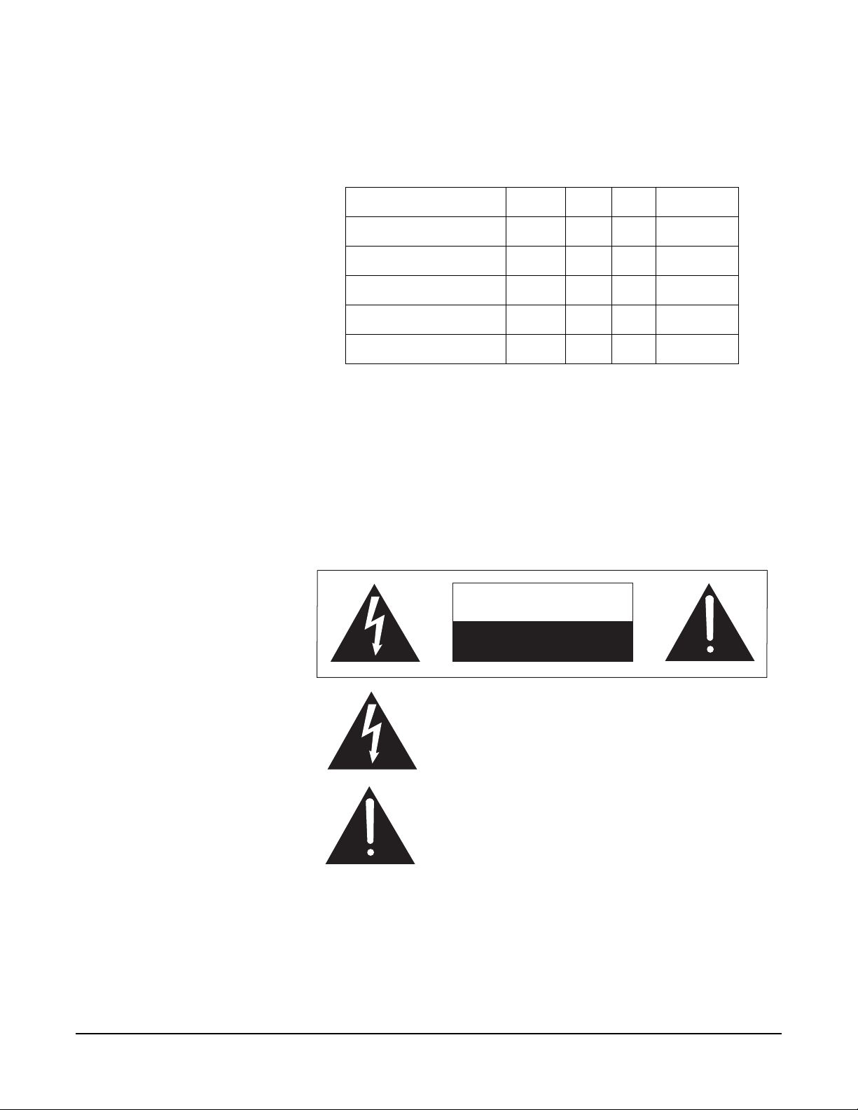
OSHA (Occupational Safety Health Administration) guidelines on
the maximum allowable time exposure to sound pressure levels
that will cause hearing damage are as follows:
8 hours at 90 dB SPL
4 hours at 95 dB SPL
2 hours at 100 dB SPL
1 hour at 105 dB SPL
30 mins at 110 dB SPL
15 min at 115 dB SPL
Never expose your ears to 120dB SPL or higher/ Damage will
occur.
Please familiarize yourself with the safety symbols in Figure 1.
When you see these symbols on this product, they warn you of
the potential danger of electric shock if the station is used
improperly. They also refer you to important operating and
maintenance instructions in the manual.
CAUTION
RISK OF ELECTRIC SHOCK
DO NOT OPEN
This symbol alerts you to the presence of uninsulated dangerous
voltage within the product's enclosure that might be of sufficient
magnitude to constitute a risk of electric shock. Do not open
the product's case.
This symbol informs you that important operating and maintenance instructions are included in the literature accompanying
this product.
Figure 1: Safety Symbols
iv
PRC-2 UHF Multi-Frequency Belt-Pack IFB Receiver
Vitec Group Communications
Page 7
1
INTRODUCTION
INTRODUCTION
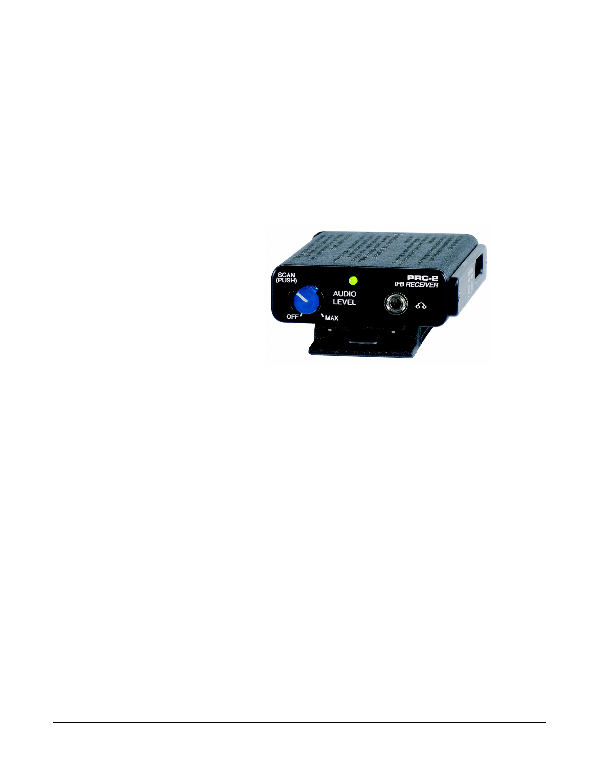
Thank you for selecting the ClearCom frequency agile, PRC-2 IFB
Receiver. The PRC-2 is the result of extensive engineering e xperience
with the very latest components. The design addresses the most
demanding professional applications.
Figure 1-1: PRC-2 IFB Receiver
The ClearCom PRC-2 Receiver along with the companion PTX-3
transmitter allow on-air talent to monitor program audio , and to receive
cues from directors and other production personnel.
The PRC-2 Receiver is housed in a rugged, machined aluminum
package for lasting performance in abusive environments
Only the PRC-2 IFB Receiver is covered in this manual. The
companion PTX-3 transmitter is covered in a separate manual. The
PRC-2 IFB Receive will operate with any ClearCom PTX-3 IFB
Transmitter in the same frequency block.
GENERAL TECHNICAL DESCRIPTION
The PRC-2 has a number of important and useful feature upgrades:
1. Two rotary HEX switches to manually set the operating frequency
2. Automatic sensing/control of a mono phone plug to eliminate the
mono/binaural switch
3. A multi-color LED for battery status. The Frequency scan and
memory features were retained.
The PRC-2 Receiver is comprised of a number of functional
subsystems as shown in Figure 1-2 Control Panel and Figure 1-6
Receiver Block Diagram.
Vitec Group Communications
PRC-2 UHF Multi-Frequency Belt-Pack IFB Receiver
1-1
Page 8

GENERAL FEATURES
The frequency agile IFB PRC-2 FM Receiver is designed to operate
with the ClearCom PTX-3 Transmitter and features microprocessor
control of 256 frequencies of operation within each frequency block.
Each block covers 25.5 MHz with 0.1 MHz frequency spacing. Any
one of ten different frequency blocks are factory available from 512
MHz to 805.5 MHz (except 608 to 614 MHz).
The unique microcontroller design in this receiver provides simple one
knob and one LED operation for audio level, switching frequencies
(channels), and easy on-the-fly programming. The receiver frequency
can be set by manually using the two rotary HEX swit ches on the side
of the unit or by using the automatic scan and store function, or both.
When powered ON, the receiver will default to the frequency set by the
switches. A nonvolatile memory can store up to five additional
frequencies accessible by pressing the knob. The memory remains
during power OFF and even with the battery removed.
The IFB PRC-2 Receiver uses 20 kHz FM deviation for efficient use of
the bandwidth and a single band compandor for clean quiet audio.
The Pilot Tone squelch locks the reception to the mating IFB PTX-3
Transmitter and ignores other signals.
The receiver operates on one 9 Volt alkaline battery for up to 8 hours
and features a tricolor LED low battery indicator. The voltages are
internally regulated for stability.
The receiver is housed in a compact, rugged, lightweight aluminum
enclosure. The unit features a durable removable belt clip and an
integral swing-aside battery compartment door.
CONTROL KNOB
The single front panel control knob performs multiple functions;
1. Rotate for Power ON/OFF
2. Rotate for Audio Level
3. Push quick, Channel Switching
4. Push and rotate for Scan
5. Channel programming
Refer to the RECEIVER OPERATING INSTRUCTIONS for full details
on how to use the single knob control for channel selection, scanning,
and programming of the five memory locations.
1-2
PRC-2 UHF Multi-Frequency Belt-Pack IFB Receiver
Vitec Group Communications
Page 9

Figure 1-2: PRC-2 Control Panel
LED INDICATOR
The three color LED indicator on the front panel provides multiple
functions.
CHANNEL NUMBER - The LED will blink OFF a number of times
corresponding to the Channel Number when the unit is switched ON
and also when a new frequency is added to an open channel. For
example, for channel 3 the LED would blink OFF three times. After
blinking the channel number the LED will return to a steady ON
indicating normal operation.
BATTERY STATUS – During normal operation, when the LED is
GREEN, the battery is good. When the LED is YELLOW the battery is
getting low. When the LED is RED, the battery is nearly depleted and
should be replaced.
PROGRAMMING FUNCTIONS - In the programming mode, the LED
will blink at a fast rate to indicate scanning for an active frequency. It
also flashes briefly to indicate a frequency has been programmed into
a channel.
HEADPHONE JACK
On the front panel (Figure 1-2 and Figure 1-4) is a 3.5mm mini phone
jack to accommodate a standard mono or stereo type 3.5 mm plug.
The unit will drive low or high impedance earphones. The jack is also
the receiver antenna input with the earphone cord acting as the
antenna. The cord length is not critical but must be at least 6 inches
minimum.
Strain relief to avoid accident al disconnect ion can be provided with the
included small hook and loop strip. Attach the adhesive strip side to
the side of the receiver with the opening end of the strip up - place the
cord in the strip and secure.
Vitec Group Communications
PRC-2 UHF Multi-Frequency Belt-Pack IFB Receiver
1-3
Page 10

Figure 1-3: Headphone Cord Strain Relief
MONO PLUG/STEREO PLUG USAGE
A Mono plug or a Stereo plug can be used with the PRC-2 headp hone
jack directly. When a Mono plug is inserted, a special circuit senses
the “ring” to “sleeve” short and automatically switches off the ring to
prevent excess battery drain. To reset, switch power OFF then back
ON.
AUDIO LEVEL
Headphones and ear pieces vary widely in their sensitivity and their
impedance making it impossible to design a receiver with a fixed
output power level that is correct for all situations. High impedance
phones (600 to 2000) Ohms will have an inherently lower power level
due to their high impedance and likewise low impedance phones may
be extremely loud.
CAUTION! Always set the Audio Level knob to minimum
(counter-clockwise) when plugging phones into the jack, then
adjust the knob for a comfortable audio level.
1-4
FREQUENCY ADJUSTMENT
These two rotary switches adjust the center frequency of the carrier.
The 1.6M is a coarse adjustment and the 100K is the fine adjustment.
Each transmitter is factory aligned at the center of its operating range.
The default position of the frequency select switches is in the center of
the transmitter’s range. The receiver and transmitter switches must be
set to the same number/letter combination for proper operation.
To gain access to these switches, slide the access door sideways with
a fingernail.
PRC-2 UHF Multi-Frequency Belt-Pack IFB Receiver
Vitec Group Communications
Page 11

Figure 1-4: Frequency Adjustment Controls
Figure 1-5: Frequency Adjust
Vitec Group Communications
PRC-2 UHF Multi-Frequency Belt-Pack IFB Receiver
Figure 1-6: R1a Block Diagram
1-5
Page 12

RECEIVER OPERATING INSTRUCTIONS
Before operating a receiver, one or more IFB PTX-3 transmitters must
be placed in XMIT mode, with each transmitter set to the desired
frequency and connected to a proper antenna, audio source, and
power source. The transmitter frequency block must be the same as
the receiver frequency block as marked on each unit.
RECEIVER NORMAL OPERATION (ALREADY PROGRAMMED)
1. Set the Frequency of the receiver to match the frequency of the
transmitter by using the two HEX rotary switches located on the side
of the receiver under the sliding door. The 1.6M switch is for
“coarse” adjustment (1.6 MHz per click) and the 100k switch is for
“fine” adjustment (0.1 MHz per click). Setting both to zero (00) is the
low frequency end of the block and setting both to F (FF) is the
highest frequency end of the block.
2. Plug an earphone or headset into the 3.5mm jack. Be sure the unit
has a good battery.
3. Rotate the knob clockwise to switch the power ON (Do NOT hold the
knob in while switching power ON). The LED will illuminate. Rotate
the knob to set the desired audio level.
4. If channel frequencies have been stored in the memory, change
channels by pressing the knob briefly and release. The LED will
blink the next channel number (frequency) and the receiver will
resume operation on that channel. If no channel frequencies have
been stored when pressing the knob to change channels, the LED
will flash from green to red to yellow to green, indicating no stored
channels and the unit will resume operation on the channel set by
the switches.
5. Whenever power is switched ON, the unit operation defaults to the
channel frequency set by the switches.
1-6
PROGRAMMING- ADD A NEW FREQUENCY TO THE NEXT OPEN CHANNEL
1. Position the receiver at a location within 20 to 100 feet of the
transmitter or transmitters.
2. With the power ON, depress the knob until the LED starts rapidly
blinking, then release the knob.
3. The unit goes into program mode and does a scan/search.
Previously programmed frequencies will be automatically skipped.
When the unit stops on a new frequency audio from the transmitter
will be heard in the earphone and the LED will stop blinking rapidly
and will change to a slow blink mode.
The unit is now waiting for an operator decision. You must now
decide to either SKIP or STORE the frequency (step 4 or 5 below.)
Switching the power to OFF without storing will delete the frequency .
4. To SKIP the frequency, depress the knob briefly and the
scan/search will resume.
PRC-2 UHF Multi-Frequency Belt-Pack IFB Receiver
Vitec Group Communications
Page 13

5. To STORE the frequency into a channel memory, depress the knob
until the LED blinks the new channel number , then release the knob.
The frequency is now stored in an open channel.
6. The unit will continue to scan/search for other frequencies. To store
more frequencies repeat steps 4 and 5 above. Up to 5 frequencies
can be stored in memory channels.
7. When all desired frequencies are stored switch the power to OFF for
a few moments, then switch back to ON. The unit will default to the
channel number set by the switches and resume normal operating
mode.
8. The first scan is made at low sensitivity and searches for only high
level transmitter signals to avoid intermods. If the receiver does not
stop on any frequency in the first scan, that means an IFB
transmitter was not detected. In this condition the LED will change
from a fast blink to a slow blink indicating the end of the scan. The
complete scan should take 15 to 40 seconds.
9. If the receiver still does not stop on any frequency, check that the
transmitter is ON. Also, if a frequency is not received or received
but distorted, some other signal may be interfering on that
frequency. Change the transmitter to another frequency and try
again.
A second scan at high sensitivity is initiated by depressing the knob
briefly at the end of the first scan to search for low level transmitter
signals. When the scan stops and the transmitter audio is heard,
either SKIP or STORE the frequency (step 4 or 5 above).
10. Switching the POWER to OFF during any mode simply terminates
that mode and returns the unit to normal operating mode when the
power is switched back to ON.
ERASE ALL 5 CHANNEL MEMORIES
1. With power OFF, depress the knob and turn the unit ON. Continue
to hold the knob down until the LED starts rapidly blinking. The
memory is now erased and the unit will go into scan/search mode.
2. Continue from step 3 above PROGRAMMING - ADD NEW
FREQUENCY….
MULTIPLE TRANSMITTER SETUP
When using this IFB receiver in a search mode, with two or more
transmitters running at the same time, the receiver may stop on a
false signal under the following conditions:
• Two transmitters are on and transmitting.
• The distance from the transmitters to the IFB receiver is less than 5
feet.
The false hits are caused by intermodulation or mixing in the front end
of the IFB receiver. At a 5 to 10 foot distance, the two carriers are so
strong at the receiver, that even this well designed front end will mix
the carriers and produce phantom frequencies. The IFB receiver then
halts its scan and stops on these false frequencies. All receivers will
Vitec Group Communications
PRC-2 UHF Multi-Frequency Belt-Pack IFB Receiver
1-7
Page 14

exhibit this type problem at some transmitter power level and range.
You notice false signals more with a scanning mode receiver since it
will find them all.
Prevention is simple. Do one of the following:
• Do the scan with only one transmitter on at a time. (Time consuming)
• Increase the receiver to transmitter distance to at least 10 feet.
(Preferred)
BATTERY INSTRUCTIONS
The battery you use in the PRC-2 receiver should be a 9 Volt alkaline
or lithium, available almost everywhere. An alkaline battery will provide
up to 8 hours of operation and a lithium battery will provide up to 20
hours of operation. Carbon zinc batteries, even if marked “heavy duty”
will only provide about 2 hours of operation. Rechargeable batteries
will only operate the receiver for an hour or less. Make sure your
batteries are marked “alkaline” or “lithium.” Short battery life is almost
always caused by weak batteries or batteries of the wrong type.
A green LED corresponds to a fresh battery. The LED will change to
yellow for low battery warning then to red to indicate the need for a
fresh battery. Continued use will further deplete the battery eventually
causing the LED to automatically turn itself off and remain off until a
fresh battery is installed.
To replace the battery, open the bottom battery door cover with your
thumb, rotate the door until it is perpendicular with the case and allow
the battery to fall out of the compartment into your hand. It is difficult to
install the battery backwards. Observe the large and small holes in the
battery contact pad before inserting a new battery. Insert the contact
end of the battery first, making sure the contacts are aligned with the
holes in the contact pad, and then swing the door closed. You will feel it
snap into place when it is fully closed.
1-8
PRC-2 UHF Multi-Frequency Belt-Pack IFB Receiver
Vitec Group Communications
Page 15

Figure 1-7: Battery Replacement
Vitec Group Communications
PRC-2 UHF Multi-Frequency Belt-Pack IFB Receiver
1-9
Page 16

TROUBLESHOOTING
SYMPTOM POSSIBLE CAUSE
LED not lit
No sound in headphone
• Battery not installed or depleted
• Power switch not on.
• AUDIO LEVEL turned all the way
down.
• Headphone plug not inserted fully.
• Defective headphone
• Transmitter not operating. (See
separate transmitter manual.)
• Receiver not on the same frequency
as the transmitter.
• Refer to “Programming - Add a New
Frequency” on page 7.
• Transmitter gain (audio level) is far
too high. Check mod level lamps
on transmitter as it is being used.
Refer to Operating Instructions
section in the transmitter manual
for details on gain adjustment.)
Distorted sound
Hiss and noise
• Receiver output may be mismatched
with the headset or earphone.
Adjust Audio Level on receiver to
the correct level for the headset or
earphone
• Excessive wind noise or breath
“pops.” Reposition microphone
and/or use a larger windscreen.
• Receiver may be tuned to an
intermod. Reprogram the
receiver.
Transmitter gain (audio level) far
too low.
1-10
PRC-2 UHF Multi-Frequency Belt-Pack IFB Receiver
Vitec Group Communications
Page 17

SYMPTOM POSSIBLE CAUSE
• Receiver antenna missing or
obstructed.
Audible dropouts
Short range
• Headphone cable is the antenna.)
• Transmitter antenna missing or
obstructed.
• Operating range too great.
• Receiver earphone cable is also the
antenna. Make sure the cable is
not coiled or wound up or
wrapped around the receiver
case.
Vitec Group Communications
PRC-2 UHF Multi-Frequency Belt-Pack IFB Receiver
1-11
Page 18

1-12
PRC-2 UHF Multi-Frequency Belt-Pack IFB Receiver
Vitec Group Communications
Page 19

2
SPECIFICATIONS
Operating frequencies:
537.6 MHz to 608, 614 to 793.5MHz (in
10 blocks)
Number of frequencies:
256 per block (using 26 MHz wide band)
Channel spacing:
100 kHz
Frequency control:
Crystal Controlled Phase Locked Loop
Sensitivity:
1 uV (20 dB SINAD)
Signal/Noise ratio:
95 dB A-weighted
Squelch quieting:
90 dB
AM rejection:
Modulation acceptance:
Spurious rejection:
Third order intercept:
Frequency response:
Pilot tone:
Audio output, headphone:
Antenna:
50 dB, 10 uV to 100 mV
±20 kHz
Greater than 70 dB
0 dBm
100 Hz to 10 kHz, (±1dB)
29.997 kHz, 4.5 kHz deviation (fixed
crystal controlled)
1 Vrms into 50 ohms minimum
Headphone cable
Programmable memory:
Vitec Group Communications
PRC-2 UHF Multi-Frequency Belt-Pack IFB Receiver
5 frequencies
2-1
Page 20

Front panel controls:
Indicators:
Power requirement:
Power consumption:
Allen wrench for knob:
Weight:
Single knob controls Audio Output Level,
Power on, programming and Scan
Frequency Selection
1 tricolor LED Indicator for poweron,
blinks to indicate channel number, blinks
fast during scan, and turns yellow or red
for low battery.
Single 9V Alkaline Battery for
approximately 8 hours operation.
60 mA.
0.035”
7.3 oz with battery
Size:
3.6 x 2.4 x 0.8 inches (housing only, belt
clip and knob extend beyond the
housing.)
Notice About Specifications
While Clear-Com makes every attempt to maintain the accuracy of the
information contained in its product manuals, that information is subject to
change without notice. Performance specification s included in this ma nu al are
design-center specifications and are included for customer guidance and to
facilitate system installation. Actual opera ting performa nce may vary.
2-2
PRC-2 UHF Multi-Frequency Belt-Pack IFB Receiver
Vitec Group Communications
Page 21

LIMITED WARRANTY
Vitec Group Communications (VGC) warrants that at the time of
purchase, the equipment supplied complies with any specification in
the order confirmation when used under normal conditions, and is free
from defects in workmanship and materials during the warranty period.
During the warranty period VGC, or any service company authorized
by VGC, will in a commercially reasonable time remedy defects in
materials, design, and workmanship free of charge by repairing, or
should VGC in its discretion deem it necessary, replacing the product
in accordance with this limited warranty. In no event will VGC be
responsible for incidental, consequential, or special loss or damage,
however caused.
WARRANTY PERIOD
Return Material Authorization
(RMA) numbers are required
for all returns.
Both warranty and
non-warranty repairs are
available.
The product may consist of several parts, each covered by a different
warranty period. The warranty periods are:
• Cables, accessories, components, and consumable items have a
limited warranty of 90 days.
• Headsets, handsets, microphones, and spare parts have a limited
warranty of one year.
• UHF wireless IFB products have a limited warranty of one year.
• UHF wireless intercom systems have a limited warranty of three
years.
• All other Clear-Com and Drake brand systems and products,
including beltpacks, have a limited warranty of two years.
The warranty starts at the time of the product’s original purchase. The
warranty start date for contracts which include installation and
commissioning will commence from the earlier of date of the Site
Acceptance Test or three months from purchase.
TECHNICAL SUPPORT
To ensure complete and timely support to its customers, VGC’s User
Support Center is staffed by qualified technical personnel. Telephone
and email technical support is offered worldwide by the User Support
Center.
Vitec Group Communications
Warranty
The User Support Center is available to VGC’s customers during the
full course of their warranty period.
Instructions for reaching VGC’s User Support Centers are given below.
i
Page 22

T elephone for Europe, Middle East and Africa: +49 40 6688 4040 or
+44 1223 815000
Telephone for the Americas and Asia: +1 510 337 6600
Email: vitec.support@AVC.de
Once the standard warranty period has expired, the User Support
Center will continue to provide telephone support if you have
purchased an Extended Warranty.
For latest contact information please refer to the Service and Support
section at www.clearcom.com.
WARRANTY REPAIRS AND RETURNS
Before returning equipment for repair, contact a User Support Center
to obtain a Return Material Authorization (RMA). VGC representatives
will give you instructions and addresses for returning your equipment.
You must ship the equipment at your expense, and the support center
will return the equipment at VGC’s expense.
For out-of-box failures, use the following contact information:
Europe, Middle East and Africa
Tel: +44 1223 815000 Email: SalesSupportEMEA@vitecgroup.com
North America, Canada, Mexico, Caribbean & US Military
Tel: +1 510 337 6600 Email: SalesSupportUSA@vitecgroup.com
Asia Pacific & South America
Tel: +1 510 337 6600 Email: SalesSupportAPAC@vitecgroup.com
VGC has the right to inspect the equipment and/or installation or
relevant packaging.
For latest contact information please refer to the Service and Support
section at www.clearcom.com.
NON-WARRANTY REPAIRS AND RETURNS
For items not under warranty, you must obtain an RMA by contacting
the User Support Center. VGC representatives will give you
instructions and addresses for returning your equipment.
You must pay all charges to have the equipment shipped to the
support center and returned to you, in addition to the costs of the
repair.
EXTENDED WARRANTY
You can purchase an extended warranty at the time of purchase or at
any time during the first two years of ownership of the product. The
ii
Vitec Group Communications
Warranty
Page 23

purchase of an extended warranty extends to five years the warranty
of any product offered with a standard two-year warranty. The total
warranty period will not extend beyond five years.
Note: VGC does not offer warranty extensions on UHF wireless
intercom systems, or on any product with a 1-year or 90-day warranty.
LIABILITY
THE FOREGOING WARRANTY IS VGC'S SOLE AND EXCLUSIVE
WARRANTY. THE IMPLIED WARRANTY OF MERCHANTABILITY
AND FITNESS FOR A PARTICULAR PURPOSE AND ANY OTHER
REQUIRED IMPLIED WARRANTY SHALL EXPIRE AT THE END OF
THE WARRANTY PERIOD. THERE ARE NO OTHER WARRANTIES
(INCLUDING WITHOUT LIMITATION WARRANTIES FOR
CONSUMABLES AND OTHER SUPPLIES) OF ANY NATURE
WHATSOEVER, WHETHER ARISING IN CONTRACT, TORT,
NEGLIGENCE OF ANY DEGREE, STRICT LIABILITY OR
OTHERWISE, WITH RESPECT TO THE PRODUCTS OR ANY P ART
THEREOF DELIVERED HEREUNDER, OR FOR ANY DAMAGES
AND/OR LOSSES (INCLUDING LOSS OF USE, REVENUE, AND/OR
PROFITS). SOME STATES DO NOT ALLOW THE EXCLUSION OR
LIMITATION OF INCIDENTAL OR CONSEQUENTIAL DAMAGES OR
THE LIMIT ATION ON HOW LONG AN IMPLIED WARRANTY LASTS,
SO THE ABOVE LIMITATIONS MAY NOT APPLY TO YOU. IN ANY
EVENT, TO THE MAXIMUM EXTENT PERMITTED UNDER
APPLICABLE LAW , VGC'S LIABILITY T O CUSTOMER HEREUNDER
SHALL NOT UNDER ANY CIRCUMSTANCES EXCEED THE COST
OF REPAIRING OR REPLACING ANY PART(S) FOUND TO BE
DEFECTIVE WITHIN THE WARRANTY PERIOD AS AFORESAID.
Vitec Group Communications
Warranty
This warranty does not cover any damage to a product resulting from
cause other than part defect and malfunction. The VGC warranty does
not cover any defect, malfunction, or failure caused beyond the control
of VGC, including unreasonable or negligent operation, abuse,
accident, failure to follow instructions in the manual, defective or
improperly associated equipment, attempts at modification and repair
not approved by VGC, and shipping damage. Products with their se rial
numbers removed or defaced are not covered by this warranty.
This warranty does not include defects arising from installation (when
not performed by VGC), lightning, power outages and fluctuations, air
conditioning failure, improper integration with non-approved
components, defects or failures of customer furnished components
resulting in damage to VGC provided product.
This limited warranty is not transferable and cannot be enforced by
anyone other than the original consumer purchaser.
This warranty gives you specific legal rights and you may have other
rights which vary from country to country.
iii
Page 24

iv
Vitec Group Communications
Warranty
 Loading...