

Page 1
RM-220
2-CHANNEL REMOTE STATION
INSTRUCTION
and
SERVICE MANUAL
Clear-
COlli
Intercom Systems
945 Camelia st. Berkeley, California 94710 510-527-6666
Clear-Com 810193
8/24194
REV
. A
Page 2
Clear-Com Systems
RM
-220 2-Channel Remote Station
Instruction Manual
PIN 810193
(C) 1990 Clear-Com Systems
All
Rights Reserved
Clear-Com Systems
945 Camelia
St.
Berkeley,
Ca.
94710
U.S.A
While Clear-Com makes every attempt to maintain the accuracy
of
the information
contained in its
product
manuals, that information
is
subject to
change
without
notice.
Page 3
3
RM-220 2 Channel Remote Station
CLEAR-COM LIMITED WARRANTY
Clear-Com products are warranted to
be
free from defects
in
materials
and
workmanship
for a period
of
one
year
from the date
of
sale.
Clear-Com's sole obligation during the warranty period
is
to provide, without
charge, the parts
and
labor necessary to remedy covered defects appearing
in
products returned prepaid to Clear-Com, 945 Camelia St., Berkeley,
Ca.
94710-1484, U.S.A.
This warranty does
not
cover any defect, malfunction
or
failure
caused
beyond
the control
of
Clear-Com, including unreasonable
or
negligent operation,
abuse, accident, failure to follow instructions in the Manual, defective or improper
associated equipment, attempts at modification
and
repair
not
autho-
rized
by
Clear-Com,
and
shipping damage. Products with their serial numbers
removed
or
defaced are not covered
by
this warranty.
To
obtain warranty service, follow
the
procedures described
below
in
IIProced-
ures for Returns
ll
and
IIShipping
to
Manufacturer for Repair
or
Adjustment.
1I
This warranty is the sole
and
exclusive express warranty given with respect to
Clear-Com products.
It
is the responsibility
of
the
user
to determine before pur-
chase that this product is suitable for
the
user's intended purpose.
Any
and
all implied warranties, including the implied warranty
of
merchantability are limited to the duration
of
this express limited warranty.
Neither Clear-Com
nor
the dealer
who
sells Clear-Com products is liable for
incidental
or
consequential damages
of
any kind.
Return Shipping Instructions
Procedures for returns:
-If
repair
is
necessary, contact the dealer
where
the unit
was
purchased.
-If
repair through the dealer is not possible, contact the Clear-Com Custom-
er
Service Department, located at the factory, as directed below.
They
will is-
sue
a Return Authorization Number eRMA).
-Do
not
return
any
equipment to the factory without first obtaining a Return
Authorization Number.
©
Clear-Com Intercom Systems 1994
Rev. A
Page 4
4
RM-220 2 Channel Remote Station
-Be
prepared
to provide your
companys
name, address,
phone
number,
name
of
person
to contact regarding the repair, type
and
quantity
of
the
equipment, description
of
the defect,
and
the
equipment
serial number(s).
Questions regarding returns for repair should
be
directed to:
Customer
Service
Department
Clear-Com
Intercom
Systems
945 Camelia Street
Berkeley, California 94710-1484
Telephone:
(510) 527-6666
Fax: (510) 527-6699
Shipping to Manufacturer for Repair
or
Adjusbnent
All
shipments
of
Clear-Com equipment must be
prepaid
via United Parcel Ser-
vice
or
the
best available shipper. The
equipment
should
be
shipped
in
the
original packing container; however,
if
the original container is
not
available,
use
a suitable container that is rigid
and
of
adequate
size.
If
a substitute con-
tainer is used, the equipment should
be
wrapped
in
paper
and
surrounded
with
at
least four inches
of
excelsior
or
similar shock-absorbing material. A de-
tailed description
of
the
problem
or
work
to
be
done
should
be
included.
All
shipments should
be
directed to
the
attention
of
the Customer Service Depart-
ment
and
must include the Return Authorization Number.
Upon
completion
of
repairs, equipment will
be
returned collect via United Par-
cel Service
or
other specified shipper.
NOTICE
ABOUT
SPECIFICATIONS
Performance specifications included in this manual are deSign-center specifications
and
are included for customer guidance
and
to
facilitate system installa-
tion. Actual operating performance may vary.
BEFORE YOU BEGIN .
..
To
get
the
most
out
of
the
RM-220
Main Station, read this manual carefully.
It
will
answer
questions
you
might have
about
the
operation
and
service
of
the
components in the system. Included
is
a Troubleshooting Section that provides
causes
and
possible solutions to problems
you
might
have
with system
and
component
operation. Clear-Com's Customer Service
Department
is available
to
answer questions
not
covered in this manual.
Rev. A
©
Clear-Com Intercom Systems1994
Page 5
5
RM-220 2 Channel Remote Station
THE CLEAR-COM CONCEPT
Clear-Com
is
a closed-circuit intercom system that consistently provides highclarity communication in high-noise and low-noise environments. A basic system consists
of
a single- or multi-channel
power
supply
or
main station con-
nected to various single-
or
multi-channel remote stations,
such
as beltpacks
and
loudspeaker stations.
Clear-Com manufacrures a wide variety
of
both portable
and
fixed-installation
units.
All
are compatible with
each
other. Clear-Com intercom systems
can
also interface with
?ther
communication systems
and
devices.
Clear-Com stations are interconnected with two-conductor, shielded microphone
cable, using 3-pin
XLR
connectors.
One
wire carries
the
DC
power
(28-30 volts) from a main station or power supply to all remote stations,
and
the
other wire carries 2-way (duplex) audio information. The shield acts as a
common
ground.
One
termination
(per
channel)
is
needed
throughout the in-
tercom network,
and
is
usually located
in
the
main station or
power
supply.
Clear-Com
is
a distributed amplifier system; each main
and
remote
station
houses its
own
mic preampliller, headset
or
speaker
power
amplifier,
and
signaling drcuitry. Low-impedance mic input lines (200 Ohms)
and
specially
designed circuitry make Clear-Com channels virrually immune to
RFI
and dim-
mer
noise.
Clear-Com main stations, power supplies
and
certain remote stations
each
have
an
auxiliary program input with its
own
volume control, which allows
an
exter-
nal audio source to
be
fed to the intercom system.
Visual Signal Circuitry
(CALL
Lights), a standard fearure
on
most main
and
re-
mote stations, allows the user to attract the attention
of
operators
who
have re-
moved their headsets.
Depending
upon
the type
of
main
and
remote stations selected
and
assuming
that
enough
DC
power
is
available, a maximum
number
of
remote stations
from
10
(all speaker stations) to 30 (all headset stations)
can
be
distributed
along a mile
of
wire. Remote stations bridge the intercom line
at
a very high
impedance (>10 KOhms), and place a minimum load
on
the line.
The
audio
level always remains constant, and does not flucruate
as
stations leave
and
join
the
network.
© Clear-Com Intercom Systems 1994
Rev. A
Page 6
6
RM-220 2 Channel Remote Station
DESCRIPTION
The
"PL-Pro"
RM-220
is
one
of
a series
of
professional intercom stations specifi-
cally designed for the broadcast industry. This 2 channel,
one
rack
space
sta-
tion
is
ideal for
ENG
and
EFP
trucks, production studio consoles,
and
small
TV
facilities. The station can
be
tailored
to
your
needs through it's programmable
"Talk"
button options. The
RM-220
is
compatible with all Clear-Com Party-Line
intercoms,
The station also incorporates a single channel program interrupt system (lFB)
in
the
station. When activated,
one
or
more stations
can
interrupt
the
program
to a talent with Clear-Con's wired
or
wireless talent receivers. Direct connec-
tion
to
Clear-Corn's
IFB
system
is
easily accomplished through a 1/4 inch
phone
jack
on
the rear panel intended to directly connect
to
a Clear-Com
MA-4.
The
RM-220
remote
speaker/
headset station allows selectable two channel
talking
and/or
listening
on
a Clear-Com Intercom System.
The
operator can
communicate
on
either
of
the channels separately
or
on
both
at once. Illumi-
nated dual action talk buttons are electronic momentary
or
latching.
The
latch-
ing feature may
be
disabled if desired. Also the talk buttons can
be
remote
controlled for footswitch
or
other use. Monitoring activity
is
possible through
the
speaker
or
headset
or
both at once.
The
RM-220
features Visual
Call
Signaling to attract the attention
of
operators
who
have removed their headsets
or
turned off their speakers.
This station accepts dynamic headsets. The station accepts two different
lengths
of
plug-in gooseneck microphones,
9"
and
18",
to
allow for different
operating locations/positions.
The station's speaker can
be
turned
on
or
off
by
a convenient front
panel
switch
when
private conversation via the headset
is
desired. A "speaker dip-
ping" circuit will give you
an
additional amount
of
acoustic output before feed-
back. This feature helps
to
reduce feedback
when
stations are placed
in
close
proximity
to
each other. The station accepts a balanced Program
input
for
mOnitoring external audio in the headset
or
speaker. Individual sidetone con-
trols for
each
channel allows the operator
to
vary the level
of
his/her
own
voice as heard in the headset/speaker.
Rev. A @ Clear-Com Intercom Systems1994
Page 7
7
RM-220 2 Channel Remote Station
"Studio Announce" allows control
of
a paging
speaker
in
a studio. A front
pan-
el
button
activates this function
and
an
assodated
relay.
The
RM-220
installs
in
a standard
19"
equipment
rack, using
only
one
rack
space. The
station provides
two
3-pin,
XLR
connectors for
Input
and
loop-
through
on
each
channel.
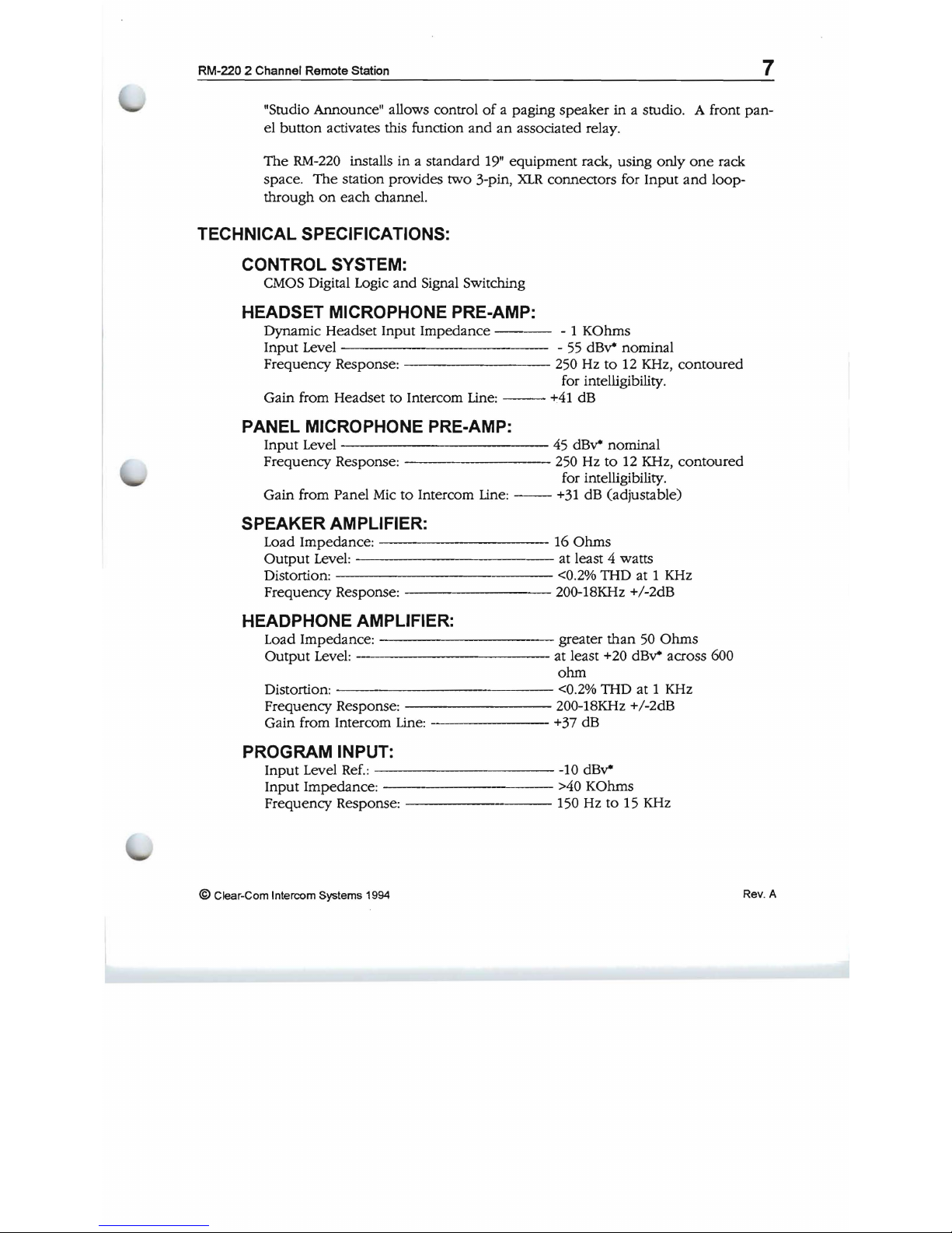
TECHNICAL SPECIFICATIONS:
CONTROL SYSTEM:
CMOS Digital Logic
and
Signal Switching
HEADSET MICROPHONE PRE-AMP:
Dynamic Headset Input
Impedance
---
- 1 KOhms
Input Level - 55
dBv*
nominal
Frequency Response: 250 Hz
to
12 KHz,
contoured
for intelligibility.
Gain from Headset
to
Intercom Line:
--
+41
dB
PANEL MICROPHONE PRE-AMP:
Input
Level
------------
45
dBv*
nominal
Frequency Response: 250 Hz
to
12 KHz,
contoured
for intelligibility.
Gain from Panel
Mic
to
Intercom
Line:
--
+31
dB (adjustable)
SPEAKER AMPLIFIER:
Load Impedance:
----------
16
Ohms
Output
Level: at least 4 watts
Distortion:
<0.2%
THD at 1 KHz
Frequency Response: 200-18KHz +/-2dB
HEADPHONE AMPLIFIER:
Load Impedance:
----------
greater
than
50
Ohms
Output
Level: at least +20
dBv*
across 600
ohm
Distortion:
------------
<0.2% THD
at
1 KHz
Frequency Response: 200-18KHz +/-2dB
Gain from Intercom Line: +37 dB
PROGRAM INPUT:
Input
Level
Ref.:
----------
-10
dBv*
Input
Impedance
: >40 KOhms
Frequency Response: 150 Hz to 15 KHz
© Clear-Com Intercom Systems 1994
Rev. A
Page 8
8
RM-220 2 Channel Remote Station
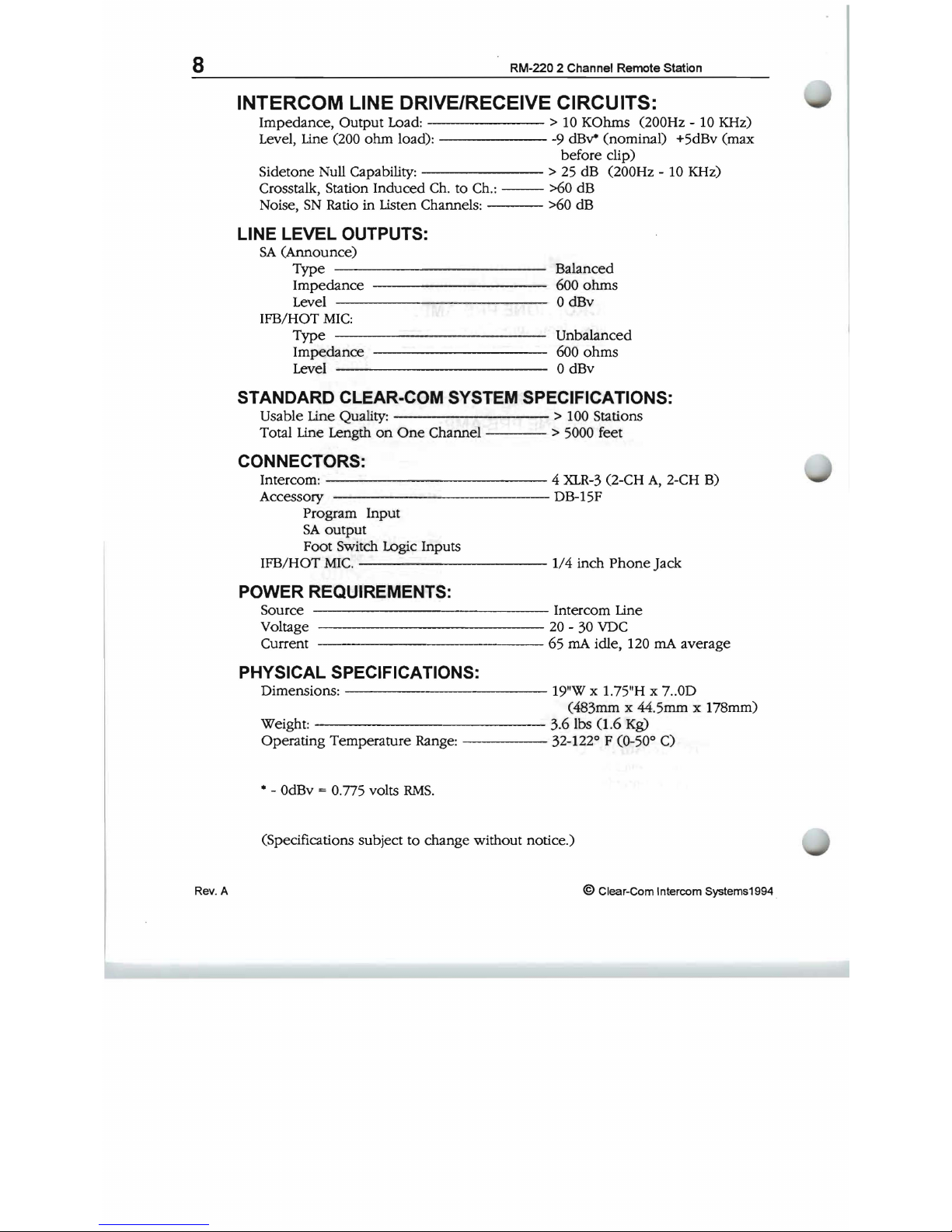
INTERCOM LINE DRIVE/RECEIVE CIRCUITS:
Impedance, Output Load:
------
> 10 KOhms (200Hz - 10 KHz)
Level, Line (200
ohm
load): -9
dBv*
(nominal) +5dBv (max
before clip)
Sidetone Null Capability:
-------
>
25
dB (200Hz - 10 KHz)
Crosstalk, Station Induced Ch. to Ch.: >60 dB
Noise,
SN
Ratio
in
Listen Channels: >60 dB
LINE LEVEL OUTPUTS:
SA
(Announce)
Type
Balanced
Impedance
---
-~---
~
600
ohms
Level 0 dBv
IFB/HOT
MIC:
Type
--------
--
---------
Unba~nced
Impedance
---------
600
ohms
Level 0 dBv
STANDARD CLEAR-COM SYSTEM SPECIFICATIONS:
Usable Line Quality:
--------
> 100 Stations
Total Line Length
on
One
Channel > 5000 feet
CONNECTORS:
Intercom:
----
--
------
4
XLR-3
(2-CH
A,
2-CH B)
Accessory DB-15F
Program Input
SA
output
Foot Switch Logic Inputs
IFB/HOT
MIC.
--
---
-----1/4
inch
Phone
Jack
POWER REQUIREMENTS:
Source Intercom Line
Voltage
------------
20
- 30
VDC
Current 65
rnA
idle, 120
rnA
average
PHYSICAL SPECIFICATIONS:
Dimensions:
-------------
19"W x 1.75"H x 7 ..0D
(483mm x 44.5mm x 178mm)
Weight:
------------
3.6 lbs 0 .6 Kg)
Operating Temperature Range: 32-122° F
CO-50°
C)
• -
OdBv
= 0.775 volts
RMS.
(Specifications subject to change without notice.)
Rev. A
© Clear-Com Intercom Systems1994 .
Page 9
9
RM-220 2 Channel Remote Station
INSTALLATION
This section discusses the installation
of
the
RM-220
in
an
intercom system.
Typical applications, overall installation theory,
and
detail
of
each
connector,
and
adjustment
of
the
RM-220
are discussed.
INSTALLATION OVERVIEW
This section describes the Clear-Com concept in intercom line interconnection.
The
following subjects are discussed:
• Intercom Line Connection
• Line Termination
• Station Powering
• Cable Considerations
Intercom Line Connection:
The
RM-220
provides a male
and
female
XLR-3
connector for
each
intercom
line that
are
"looped through".
Line Termination:
The
fundamental concept
of
Clear-Com Party-Line intercom is that all stations
provide high impedance current sourced signals into a single
common
system
termination.
The
line drivers in a station have a source
impedance
greater
than
10 KOhms.
The
receive
or
"listen" section
of
stations contain a 'hybrid null' circuit that at-
tempts
to
reject (null) any "talk" signal being sent
by
that station
on
that chan-
nel.
The
'hybrid null' circuit
depends
on a known
impedance
on
the
intercom
line
to
accomplish this. Variations in impedance
on
the
line
upset
the
'null'.
CAUTION:
All
Clear-Com Intercom lines must
be
terminated.
Care
must
be
taken
not
to
fail
to
terminate
or
to
'double' terminate a line.
All
unused
in-
tercom inputs must
be
terminated to
keep
the
line drive circuits stable.
The
RM-220
does
not
provide termination
on
the intercom line. Clear-Com
main stations
and
power
supplies provide switch selectable termination net-
works
on
all intercom
output
lines. It
is
up
to
the
user
to
determine
where
the
termination will
be
provided.
An
unterminated line will cause excessive levels,
possible oscillation
of
line drivers,
and
sever unbalance
of
hybrid null net-
works. A
double
or
multiple terminated line will cause
low
levels
and
sever
unbalance
of
hybrid null circuits.
©
Clear-Com Intercom Systems 1994
Rev. A
Page 10
10
RM-220 2 Channel Remote Station
The
termination
of
an
intercom line (or channel) is a 220
Ohm
resistor in series
with a 4.7 KOhm that
is
paralleled with a
10
uF capacitor.
Station Powering:
The
RM-220
needs +20 to
+30
volts between pins 1
and 2 of
the intercom con-
nectors. Typical Clear-Com systems are powered
by
a Main Station
or
a Power
Supply.
Clear-Com
power
supplies can
be
paralleled to increase the
number
of
RE-
MOTE
STATIONS
that can
be
operated in a system.
Cable Considerations:
The
Clear-Com intercom line
is
intended to run
on
a shielded twisted pair
of
cable
per
channel
of
intercom.
One
conductor carries full duplex ("two-way")
audio, the
other
conductor carries the
DC
power
for remote stations.
The
shield
is
used
for ground return for audio
and
power.
When
choosing inter-
connect cable,
keep
the following considerations in mind:
1
DC
resistance
of
the ground
or
common conductor affects crosstalk.
For runs longer than 500 feet
do
not
use wire smaller
than
20 gauge.
2 The capacitance
of
the interconnect cable affects system frequency
response
and
sidetone stability. Total capacitance should
not
be
greater than 0.25
uFo
Portable Installation Cable: Practical cable for portable system interconnections
is
flexible, two-conductor, shielded microphone cable. For runs less than
500 feet a cable
made
of
24
gauge wire is acceptable. For runs longer than 500
feet
use
a 20 gauge cable
or
larger.
Permanent
installation Cable: Vinyl-jacketed shielded pair
is
the cable
of
choice for permanent installations. Use a low-capacitance
20
gauge
wire for
short runs
(under
500 feet) and 18 gauge cable for runs greater
than
500 feet.
Placing the cable in conduit
is
recommended but not necessary.
Multi-pair cable that is indiVidually shielded
is acceptable for use in multi-
channel systems. For cross-talk considerations the shields must
be
tied togeth-
er
on
both
ends
of
the cable to
produce
the lowest possible
DC
path
for
ground
return.
Rev. A © Clear-Com Intercom Systems1994
Page 11
11
RM-220 2 Channel Remote Station
DESCRIPTION OF CONNECTORS
Headset Connector (Front Panel)
NOTE ABOUT
HEADSETS:
The following
is
a description
of a recommended
headset.
Mic
Type - Dynamic
Wiring: Pin 1 - mic
common
Impedance - 150-250 Ohms Pin 2 - mic
hot
Output
--
-55dB Pin 3 -
headphone
common
Headphone
- Dynamic
Pin 4 -
headphone
hot
Impedance - 50-2000 Ohms
Panel Mic Connector (Front Panel)
Clear-Com provides two plug-in panel microphones for
use
on
the
RM-220
.
The
GM-9
is 9 inches long and
GM-18
is
18
inches long.
The
microphone
is
of
the electret type. The microphone has a builtin 1/4 inch
phone
jack for a con-
nector. A mating receptical is mounted
on
the
RM-220.
To
install a
GM-9
or
GM-18
panel mount microphone
use
the
following steps :
1 Check the set screw in the mic mounting flange
to
make
sure
it is
clear
of
the threads in
the
bushing.
2 Screw the microphone into the bushing
hand
tight.
3 Set the set screw
on
top
of
the bushing
to
lock the mic
in
place.
Intercom Line Connectors (Rear Panel, XLR-3 2 male & 2 female)
The
RM-220
has a male and female pair
of
XLR-3
connectors for
each
intercom
line.
The
male-female pair
of
connectors are wired parallel
and
intended
for
loop-thuough connection.
The
pinout
of
the Intercom Connectors is as follows:
Ground (Shield)
• Pin
1
• Pin 2
Power (+20
to
+30
VDC)
• Pin 3 Audio
©
Clear-Com Intercom Systems 1994 Rev. A
Page 12

12
RM-220 2 Channel Remote Station
IFB/HOT Mic (Rear panel, 1/4 inch Phone Jack)
A
1/4
inch
phone
jack marked IFB/HOT Mic provides a 0 dB
output
signal
from the selected microphone. This
output
is
intended
to
work
with
Clear-
Com's
MA-4
IFB
control panel. A control signal into this
connector
from
the
MA-4
cause
all active Talks from
the
station
to
cease
and
only
send
an
output
to
this output.
The
pin
description
of
the
connector is
as
follows:
• Tip Microphone Audio
Output
• Ring Control Signal (>15 VDC)
• Sleeve - Ground (Shield)
ACCESSORY (Rear Panel, DB-15F)
The
Accessory DB-15F connector
on
the
rear
panel
provides
Program Input,
Announce
Audio
Output,
Announce
Relay Contacts,
and
Foot Switch inputs for
activating a Talk
on
either channel. The
pin
assignment
of
the
connector
is
as
follows:
"ACCESSORY"
CONNECTOR
DB-15F
FOOT SWITCH COMMON
FOOT SWITCH "S"
FOOT SWITCH "A"
GND.
ANNOUNCE RELAY N.
C.
CONTACT
ANNOUNCE RELAY WIPER
ANNOUNCE RELAY
N.O. CONTACT.
GND.
GND .
• ANNOUNCE AUDIO OUTPUT
+ANNOUNCE
AUDIO OUTPUT
PO\t\ER
(+30
VDC)
GND .
• PROGRAM INPUT
+ PROGRAM INPUT
Viewed from the rear
of
the connector
Rev. A
© Clear-Com Intercom Systems1994
Page 13

13
RM-220 2 Channel Remote Station
DESCRIPTION OF OPTIONS AND ADJUSTMENTS
Dip Switch Option Switches (Rear Panel)
Eight dip switches
on
the
rear panel enable various options
in
the
station.
• Momentary only action only
on
the
TALK
switches.
• Automatically send a
CALL
signal
when a TALK
is active.
• Interrupt any active
TALKs
when
the
ANNOUNCE
button
is pressed.
• Interrupt any active
TALKs
when
the
IFB
drcuit
is activated.
• Feed
PROGRAM
audio
to
Chan.
"B"
and
disable the monitoring
of
PROGRAM
with the front panel control marked
PROGRAM.
• Interrupt the
PROGRAM
feed to Chan.
"B"
when a CALL
signal is
present
on
Chan.
"B".
The
RM-220
is shipped from
the
factory with all dip switches
in
the
OPEN
position.
To
enable a function place that
dip
switch
in
the
CLOSE
position.
w
Cf)
Z
o W
-.J
a..
(J
0
"-----
1
-MOMENTARYONLYTALKSW"A"
~:-:
2 - MOMENTARY ONLY TALK
SW"B"
~
- 3
-AUTO
CALL SIGNAL
ON
CHAN. "A"
- 4 - AUTO CALL SIGNAL
ON
CHAN. "B"
r-s~~i-i
5
-ANNOUNCE
TALK INTERRUPT ENABLE
- 6 - IFB TALK INTERRUPT ENABLE
- 7 -- PROGRAM FEED ENABLE CHAN. "B"
"-----
8 - INTERRUPT PROGRAM CHAN "B"
Mute Level Adjust (Rear Panel)
When a TALK
button is pressed
the
listen level in the Speaker will
"MUTE"
or
"DIP"
to a lower level that
is
set
by
the
MUTE
LEVEL
control.
To
disable the
function,
tum
the
control fully clock-wise.
The
maximum DIP is approximately
10
dB in
the
full counter-dock-wise pOSition.
© Clear-Com Intercom Systems 1994
Rev.
A
Page 14

14
RM-220 2 Channel Remote Station
Panel Mic Level Adjustment (Internal)
The
microphone preamplifier for the Panel Microphone has
an
internal gain
adjustment control. This gain can
be
adjusted for different operating condi-
tions.
As
shipped from the factory the control
is
set to minimum gain such that
the panel microphone
and
a headset microphone have
the
same volume
when
worked
at
about
2 inches.
To
adjust
the
panel microphone gain, remove the
top
cover
of
the unit
and
ad-
just
R154
on
the right side
of
the printed circuit board. Refer
to
the illustration
below.
N3dO
--------
DIP!
- - --
~
- ------- -
CJ
L
--------
J1 --- -
:~D"
-
~~-;----
·~99~
~
U
~-~~:
:
~
DJRIO-2~~f>tiiii
~=~R2
~79~
I
R2S~~08
-
+04
OIl
"'1'$-
-}
m
C1
R4S=6]..J
-
ry1=l=.:-.
r:,
,W
I
~
-
"~I
'
ICI
~
RaJ
I
--
--c::F-R8z
~-R59
-- ,.t;
--c::::>-
- - -
R23
-
C9\d
---.
~R78
~010
,....
D5~1
_ - -
--c::r-R57
C80
~
'0
RTu-
r
I,
I I 8
R2
I
..........
-t=>-R58
+8-
I
~~
- _ +
--
--
05
~C44
,;;-c::::r-
R60
I
~
--c::r-RI40
t;E3C22
RI
22
-~c
' -
RI54
I I
""
~-,
Rtf4
'~---I
RI23~-
R
ICIO
~
RIZ4[J]]-<=J-~-
-
uu<',
:Jf:
~
~~
(]llh;UUU-
f1
":
.3±-~-
~---
-,If",,- - ;----
~
- - I -
74
~-RI60
!C16
I
-R51
C81~
--c::r-
CJO~
';:;'CZ9
.;:::::J--
RIOJ
- - - - I
-RSO
R~-
.R94~I'
--
-
RI~-
::§::R9B
J
I~-
os-r1-
-
u,
RI25-t=>-
---.,
C49- -
RSJ
RI05-~
-
1C1
- ...............
99
,--
-..
__
.....J
GAIN
ADJUST
Location
of
Panel Mic Gain Adjust Control R154
Rev. A
© Clear-Com Intercom Systems1994
Page 15

15
RM-220 2 Channel Remote Station
Intercom Line Length Compensation (Internal)
The
receive circuits
of
the intercom channels have
been
optimized for a Inter-
com
line
length
between
200
and
700 feet (60
and
200 meters).
The
capaci-
tance
of
the intercom line must
be
compensated for
in
the
receive circuits
if
a
good
sidetone null is to
be
achieved. When using a
speaker a good
sidetone
null
is
necessary
to
achieve a usable listening level.
A
set
of
jumpers has
been
provided for compensating for lines shorter than 200
feet
or
longer than 700 feet. Each intercom channel has its
own
jumper.
To
change
the setting
of
the Line Length Compensation Jumpers, remove the
cover
of
the
unit
and
move the jumper for
the
appropriate channel.
The
jump-
ers are next to
P3
about in the middle
of
the board. Refer the illustration
be-
low
for jumper selection. Set
each
channel for the setting appropriate for
it.
C")
a.
CHA
0
W
0
0
0
0
CHBW
0
0
0
JUMPER
SElTlNGS
>200 FT
>700 FT
<200 FT
<700 FT
t
~
W
Line Length
Compensation
Jumper
Settings
©
Clear-Com Intercom Systems 1994
Rev
. A
Page 16

16
RM-220 2 Channel Remote Station
TYPICAL SYSTEM APPLICATIONS
ENGI EFP Truck
The
following block diagram describes a typical
ENG/EFP
Truck installation.
TELEPHONE
DIRECTOR
RY-220
CHANNEL A
INTERFACE
TEL-lOOO
RIl-220
OR
AC-10H
PROGRAM
NPUT
POWER
SUPPLY
TELCO
LINE
OPERATOR
F1.00R MANAGER
CAMERA ASST. DIRECTORI
PS-22
TALENT
ANNOUNCER
CHANNEL B
Typical
ENG/EFP
Truck
Installation
The system has two 2 channel
RM-220
rack
mount
stations.
The
system is
powered
from a 1
amp
Clear-Com
power
supply that also provides
the
ter-
minations for
both
channels.
Channel B is connected to Talent Recievers for announcers.
A telephone line interface is connected to
the
Program
input
of
station #2 that
provides a program feed from the studio via a dial-up
telephone
line. Its dip
switch options
are
set
to
insert program
on
channel B
and
interrupt
the
pro-
gram
when
a call signal is present
on
channel B.
The
option
dip
switches for
placing a Call signal
on
channel B is set
on
both
RM-220s.
Now, either
RM-220
will interrupt the program feed
to
the announcer
when
a Talk is initiated from
it
to
the announcers.
Rev.
A © Clear-Com Intercom Systems1994
Page 17

17
RM-220 2 Channel Remote Station
Cable/School Television Studio
The
following block diagram describes a typical Cable
or
School Television
Studio installation.
ASSISTANT
DIRECTOR
VIDEO GRAPHICS
DIRECTOR
MR-I02
MR-I02
CAMERAS
FL.OOR MANAGERS
.
RS-501
RS-501
RS-501
RS-501
~
__
~
CHANtEL. B
PS-22
PROGRAM
INPUT
fROIA STAnON
SA OUTPUTS
PROVIDED
BY
USER
A
~
__
--,
PAGING SPK
IN
5ruOl0
"'XOI/
AlAP
Rld-220
~----------~.~----------~
RS-501
CHANNEL. A
TAL.ENT ANNOUNCER
Typical Cable
or
School Television Studio Installation
The system has several 2 channel
RM-220
rack mount stations
and
several wall
mount
2 channel stations. The system
is
powered
from a 1
amp
Clear-Com
power
supply that also provides the terminations for
both
channels.
A line
of
single channel beltpacks
is
connected to channel A. The beltpacks
are used for the cameras and floor managers. Normal communication
between
all parties
is
on
channel A.
Channel B
is
connected to Talent Receivers for announcers. Program that
is
to
feed the announcers
is
connected to the fIrst
RM-220.
Its dip switch options
are
set
to insert program
on
channel B and interrupt
the
program
when
a call
signal is present
on
channel
B.
The
option dip switches for placing a Call sig-
nal
on
channel B
is
set
on
both
RM-220s
. Now, either
RM-220
will interrupt
the program feed to the announcer
when
a Talk
is
initiated from it
to
the
announcers.
A
PA
amplifIer is connected to the
ANNOUNCE
output
of
the first
RM-220
such
that the operator
of
that station could talk directly to everyone in
the
studio.
© Clear-Com Intercom Systems 1994
Rev. A
Page 18

18
RM-220 2 Channel Remote Station
ACTUAL APPLICATIONS
This section describes detail instructions for various types
of
applications. A
block diagram such as those in the previous section describing
an
ENG/EFP
Truck
and
a Cable/School Television Studio should
be
developed
for
your
ap-
plication.
The
following sub-topics in this section describe in detail
each
of
the
major application types that might
be
encountered.
The
sub-topics in this sec-
tion are:
•
Intercom
line
Wiring
•
Program Input
•
Internal
IFB
Operation
•
External
IFB
(MA-4
and
PIC-4000 Connection)
•
PA
Feed
to
StudioOutput
•
Remote Control
of
TALK
Switches
•
Inadequate Side-Tone Adjustment
Intercom Line Wiring
The Intercom Line wiring has several purposes in the Clear-Com system.
• Interconnection
of
the audio intercom signal
between
stations.
• Delivery
of
DC
power
for remote stations such as the
RM-220
to
operate from.
• Termination
of
the intercom
audio
line external to remote stations.
Interconnect the intercom lines
of
stations
and
power
supplies using a shielded
twisted pair cable with
XLR
3 pin connectors the
same
as
used
for balanced
microphones. Refer
to
the Installation Overview section
of
this manual
on
page
9 for more information.
The
RM-220
has a male and female pair
of
XLR-3
connectors for each intercom
line.
The
male-female pair
of
connectors are wired parallel
and
intended for
loop-thuough connection.
The
pinout
of
the
Intercom Connectors are as follows:
Ground (Shield)
• Pin 1
Power (+20
to
+30 VDC)
• Pin 2
Audio
•
Pin
3
Rev
. A
@ Clear-Com Intercom Systems1994
Page 19

PROGRAM
INPUT
CAMERAS
.
t
RM-220 2 Channel Remote Station
19
The following application shows the practical interconnection
of
the intercom
lines in the block diagram
of
the Cable/School Television Studio
shown
on
page
17.
ASSISTANT
DIRECTOR
DIRECTOR
VDEO
GRAPHICS
I
:M:-l~211
I
~
I
n
t~.
rr
t .
.:;...
FLOOR
MANAGERS
~
______
~A~
______
-,
CHANNEl..
A
fROM STATION
TALENT
ANNOUNCER
CONN[CllON CODES
SA
OUTPUTS
J -
J-PIN
·XI.R"
~
-
"'-PIN
·XLR-
PIlOVlDED
BY
USER
1~ -DB-l~
B ~ 1/."
ST[RED PHONE PLUG (R'NG/llP/SL.E:EVE)
,--
____
..)A'-
____
______
C -
1/8"
..
ONO
PHONE
PlUC
(TIP/SLEEVE)
H -
SCREW
T[R>lINALS
To
W _
AC
POVo£R
CORO
Ear
P'-ce
[)J-i
>I'XER/Alo1P 1H
PACINC
CHANNEL
B
SPEAKER
Interconnecting a Small Cable/School
Television
Studio
The
entire system
is
wired using male/female microphone cables loopedthrough each station except for the MR-l02s. The MR-l02 has screw terminals
for the intercom lines.
The
PS-22
provides
the
DC
power
for
the
system
and
the
line termination switches must be turned ON.
CAUTION:
All
Clear-Com Intercom lines must
be
terminated.
Care
must
be
taken
not
to
fail
to
terminate
or
to
'double' terminate a line.
All
unused in-
tercom inputs must
be terminated
to
keep the line drive circuits stable.
The
RM-220
does
not provide termination
on
the
intercom line.
©
Clear-Com Intercom Systems 1994
Rev. A
Page 20

20
RM-220 2 Channel Remote Station
Program Input
There
are
to
different
purposes
for
the
Program Input; monitoring
program
in
the
speaker
and
headphone
or
feeding
the
Channel B
intercom
line with
pro-
gram
material.
Monitoring
Program:
To
monitor Program
in
the
headphone
or
speaker:
•
Connect
the
Program
source
to
the
proper
pins
on
the
DB-IS.
• Make
sure
that
DIP switches 7 & 8 are
set
to
the
OPEN position.
• Set
the
front
panel
control
marked
Program for
the
desired volume.
Feeding
Channel B Intercom
Line:
To
feed
the B channel
with
program
material:
•
Connect
the
Program
source
to
the
proper
pins
on
the
DB-IS.
• Set DIP switch #7
to
the
CLOSE
position.
• Set
the
Program Send Level control
on
the
front
panel
just
underneath
the
Ch. B Listen Control for
the
desired
level
on
the
Intercom line.
• If it is desired
to
interrupt this program feed
when a CALL
signal is
present
on
the
intercom line
set
DIP switch #8
to
the
Close position.
To
Connect
To
The
Program
Input:
The
Program
Input
of
the
RM-220 is
available
in
the
DB-IS Accessory Connector
on
the
rear
panel.
The
input
is
electrOnically
balanced
with
an
input
impedance
of
IO
KOhms.
The
nominal
level
should
be
OdB
+/-
IOdB.
"ACCESSORY"
CONNECTOR
DB·15F
(Viewed from the rear
of
the unit)
PQIJI,£R
(+30
VDe)
GND.
- PROGRAM INPUT
+ PROGRAM INPUT
Connecting
Program
Sources
Rev. A
© Clear-Com Intercom Systems1994
Page 21

21
RM-220 2 Channel Remote Station
Connect a balanced input to pins 8
and
15
with the shield
connected
to
pin
7.
To
connect
an
unbalanced input connect the signal to
pin 8 and
connect
the
shield to pins
15
and
7.
Connecting
Party-Line Products
As
Program Sources: If
other
Clear-Com
products
are
to
be
used
as a program source directly such as
an
AC-I0H Tele-
phone
interface
use
the following interconnection cable.
Pin 14
of
the DB-15
ACCESSORY
connector provides +30
VDC
to
power
the
external device. Connecting pins 7
and
15
together unbalances
the
Program
input. The
output
from the party line device
is
connected to
pin
8 with a
lK
ohm
load to provide a partial termination.
"ACCESSORY"
CONNECTOR
DB-15M
PCMtER
(+30
VDC)
(Viewed
from
the
rear
of
the
unit)
Connecting
Party-Line Products As Program
Sources
Internal IFB Operation
To
use
Channel B as
an
IFB
feed, connect
the
Program source to
the
Program
input
as
mentioned in the previous section
and
set DIP switches #7
and
#8 to
the
CLOSE
position.
The
program will
now
be
interrupted
whenever
there
is
a
CALL
signal present
on
Channel
B.
If there are multiple RM-220s in
the
system,
the program should only
be
feed into
one
of
the
RM-220s.
To interrupt
the
IFB
program automatically
when a TALK
on
the
B channel
is
active, set Dip Switch #4 to the
CLOSE
position. Set the same
dip
switch in
any other
RM-220
connected to
the
same channel
if
it is desired for them to in-
terrupt
the
program.
©
Clear-Com Intercom Systems 1994
Rev. A
Page 22

22
RM-220 2 Channel Remote station
ExtemallFB
(MA-4 and PIC-4000 Connection)
Clear-Com provides a stand-alone
IFB
system called a PIC-4000.
The
PIC-4000
provides four interruptable
IFB
feeds from two program sources
and
located in
a central location. The
MA-4
is
a four channel control
head
intended
to
work
with the PIC-4000. A
MA-4
is
located at
each
location
where
program interrupt
is
to
be
initiated. Each
MA-4
has its
own
panel mounted microphone
which
when
mounted
next
to
an
intercom station with a panel
mounted
microphone
causes panel congestion with two microphones at a single location.
The
RM-220
has a 1/4 inch
phone
jack
output
on
its rear panel intended
to
connect directly
to a MA-4
and
provide a microphone feed
to
the
MA-4.
The
MA-4
can
be
ordered without a panel
mounted
microphone.
When
a button
is
pressed
on
the
MA-4,
a control signal will temporarily transfer the microphone
in
use
on
the
RM-220
to the
MA-4
muting
any
Talks active
on
the
RM-220.
To connect the
RM-220
to a
MA-4,
use a two wire shielded cable with
1/4
inch
tip, ring,
and
sleeve jacks
on
each end. Connect the tip to the tip,
the
ring to
the
ring,
and
use the shield to connect
the
sleeve to the sleeve.
POWER
8UPPLY
PS-22
1/4-
ASSISTANT
PHONE
JACK
DRECTOR
'-+------
TO
ADDmONAL
PARTY
UNE
8TAND ALONE
IFB SYSTEM
..__L-----'---'-71
PIC-4000
TALENT
RECEIVERS
Typical External IFB System Using a PIC-4000
and
MA-4
with
a RM-220
Rev. A
© Clear-Com Intercom Systems1994
Page 23

23
RM-220 2 Channel Remote Station
PA Feed to Studio Output
Pressing the button marked "Announce"
on
the front
of
the
RM-220
temporarily
disables activity
of
the station
and
places the
output
of
the
selected micro-
phone
on
the ANNOUNCE AUDIO OUTPUT terminals
of
the
ACCESSORY
I/O
DB-15 CONNECTOR
on
the rear panel
of
the station. Isolated relay contacts
are
also available for controlling some external device
such
as a
PA
amplifier to
another
room.
The
audio
output
is
600 ohms impedance that
is
transformer
balanced
and
iso-
lated with a nominal
output
level
of
OdB.
To
connect to the ANNOUNCE out-
put, . connect a shielded twisted pair cable to pins
6
and
13
of
the
ACCESSORY
connector
and
use
pin
5 for connection
of
the shield.
A relay
is
provided that activates
when
the ANNOUNCE button is
pressed
and
its contacts are available
on
the
ACCESSORY
connector.
The
relay is rated for
2.0 Amps.
of
DC
current at
24
VDC.
"ACCESSORY"
CONNECTOR
DB-15F
GND.
ANNOUNCE RELAY N.C. CONTACT
ANNOUNCE RELAY WIPER
ANNOUNCE RELAY N.O. CONTACT.
GND.
GND.
-
ANNOUNCE AUDIO OUTPUT
+ANNOUNCE AUDIO OUTPUT
Connections for
Announce
Audio
and
Relay
Outputss
I
I
I
I
© Clear-Com Intercom Systems 1994
Rev. A
Page 24

24
RM-220 2 Channel Remote Station
Remote Control
of
TALK Switches
The
TALK
switches
of
the
RM-220
can
be
remote controlled with external con-
tacts that are available
on
the
ACCESSORY
connector
on
the
rear panel. A
footswitch
or
remote pushbutton
when
wired
to the
ACCESSORY
connector
acts exactly the same as pushing a
TALK
switch
on
the front panel. Both latch-
ing
and
momentary actions are active.
FOOT SWITCH COMMON
" ACCESSORY"
CONNECTOR
DB-15F
....L
FOOT SWITCH "S"
~----------------~
\r
.....
~
FOOT SWITCH "A"
Connection
of
External Talk Switches
Inadequate Side-Tone Adjustment
The receive circuits
of
the intercom channels have
been
optimized for a Inter-
com Line length
between
200
and
700 feet (60
and
200 meters).
The
capaci-
tance
of
the
intercom line must
be
compensated for in
the
receive circuits if a
good
sidetone null is to
be
achieved.
When
using a
speaker a good
sidetone
null is necessary to achieve a usable listening level.
A set
of
jumpers has
been
provided for compensating for lines shorter
than
200
feet
or
longer than 700 feet. Each intercom channel has its
own
jumper. Refer
to
page
15
for changing these jumper for optimum operation.
Rev. A
©
Clear-Com Intercom Systems1994
Page 25

25
RM-220 2 Channel Remote Station
OPERATION
Normal operation
of
the
RM-220
only requires access to
the
front
panel
con-
trols. For intercom operation set the
listen
Level controls for each channel to
desired level
and
press the Talk switches
when
talking. If a
headset
is being
used, set the sidetone control for the channel that
is
being
talked
to
for
the
de-
sired
amount
of
sidetone in the earphone. If the Panel Mic
and
Speaker are
being used,
set
the
sidetone control for minimum feed-through to
the
speaker
to prevent feedback.
The
rest
of
this section is a detailed description
of
each control.
Talk
Buttons
Each channel has its
own
illuminated "Talk" button for activating
the
micro-
phone
feed to a given channel. Mechanically the
push-button
is momentary in
action,
however
electrically the button has dual action (momentary
or
latching)
depending
on
how
the button is pressed. The latching function
can
be
de-
feated with a rear panel dip switch.
LATCHING: Pressing the button quickly will "toggle"
the
"talk" function, alter-
nately turning it
on
or
off.
MOMENTARY: Pressing
the
button for longer than 1/4
second
will
tum
the
button press into a momentary function such that
when
the
button
is released
the "Talk" function will
tum
off. In any case the
"Talk"
function is activated all
of
the time the button
is
pressed.
TALK INDICATION: The
"Talk"
button will illuminate dimly indicating
when
a
ItTalk"
is
activated.
CALL INDICATION: The
"Talk"
button will flash brightly
when a "Call"
signal
is received
on
that channel.
AUTO-CALL ON TALK: Each channel can
be
set
to
send
a call signal
when
the "talk" function
is
active. This function
is
used to activate
IFB
circuits
or
any
other "call" activated function available
on
other stations. A dip switch
option
on
the rear panel activates this function.
SPEAKER MUTE FUNCTION: Pressing either
"Talk"
button
will
cause
the
output
level
of
the
speaker to reduce
by
an
amount
set
by
the
rear
panel
Mute
control.
To
disable the function,
tum
the
Mute control fully clock-wise.
©
Clear-Com Intercom
Systems
1994
Rev. A
Page 26

26
RM-220 2 Channel Remote Station
Call Buttons
Each channel has its
own
"Call"
button. Pressing the
"Call"
button at any time
will
send a "Call"
signal
on
that channel regardless
of
the activation
of
the
"Talk" circuit for that channel.
The "Talk" button for that channel will illuminate brightly while the
"Call"
but-
ton
is
pressed indicating the presence
of a "Call"
signal
on
the line.
Listen Level Controls
Each channel has a separate "listen
Level"
control. Listening
is
always
on
and
is
not controlled by
any
logic.
To
listen
to
a channel,
tum
up
the appropriate
control.
To
not listen to a channel,
tum
the control completely off.
Side Tone Controls
Each channel has a "Side Tone" null control. This control
is
used
to
set
the
amount
of
the microphone that
is
heard in the
earphone
from that channel.
This control
is
a true hybrid null control and therefore is sensitive
to
changes in
line loading. For
headphone
use it
is
best to find the 'null' for a given channel
and then rotate the control clockwise to obtain the desired side tone level.
If the
speaker
and
panel
microphone are used together providing a possible
acoustic feedback
path
it will
be
necessary
to
use
an
almost complete 'null'
of
the side
tone
control.
Program Send Level Control for Channel B
Channel B has a "Program Send
Level"
control that sets the amount
of
program
being
sent
to that channel
when
the program
is
activated.
Speaker ON/OFF Switch
The switch marked Speaker ON/OFF
is
used to turn the speaker
on
and
off.
Mic Select Switch
The
Mic
Select Switch enables the operator
to
select which microphone is
active.
Rev. A © Clear-Com Intercom Systems1994
Page 27

27
RM-220 2 Channel Remote Station
Program Monitor Level Control
The
"Program" volume control sets the
amount
of
the program signal heard di-
rectly
in
the
headphone
or
speaker. This control only affects
what
is heard in
the
headphone
or
speaker
and
does
not affect "Program" feed to
the
intercom
lines.
NOTE: If Program is being feed to the Channel B intercom line the program
feed to the
headphone
and
speaker
is
disabled.
Announce Button
The
"Announce" button allows
the
operator to instantly
use
the microphone
input
to directly talk to a system external to
the
intercom such as a paging
speaker/amplifier in another room. A
dry set
of
relay contacts
on
the
rear pan-
el
is
also available that
can
be
used
to
activate external switching as
needed
when
the
Announce button
is
pressed.
Pressing the Announce button momentarily disables
any
active "Talks". Active
"Talk" circuits will
be
restored
when
the button
is
released.
The
"Talk" muting
action
can
be
defeated if desired by moving
an
internal jumper.
(see
section
on
internal options
and
adjustments)
© Clear-Com Intercom Systems 1994
Rev. A
Page 28

-
-------
;:u
~
»
@
0
m
..
b'
3
:;-
!ii
8
3
en
~
It)
3
CII
....
co
~
~
I
tv
tv
0
s:
~
....
::l
"'tl
n
~
~
C'Il
8
~
0-
-<
t:i
..,
~
~
5·
('JQ
,1_=
-
~-I~D~_I~----~~--------I-I~'~l~:~::::J'
Cc;)U~1
_ _
n~
Rl0-2}dJ
~-R28
-
-~
Lf
n
OL~Cj~R20R22
-C79-D-R11 - +(;34 all
R25~_
I I
OJ
08
-
-~-
:;jll--)
rt\0
- - -
~SI
R45~_
u'
'E
W
I
:gB
-
"~..,
IICI
RBJ
I
--
=
R~~2
~-RSgiii
c;.ll=-:::.-
,
~-
- - -
R2J
C9r=\
........
-c::r-R78
caD
co:
I:........:!
"""Th?,-OI0
I:'"
I
fi~O
\d~
=.g=~~
~
+8-
--c::;::t--R7
!'""'"'":.
- +--
~~
8-
05
~C44
--c:::;)--R60
9C71
.......
,-
-
"'E3CZ2
-
.JlIiS-~
I
'"
-
RHO
t;
RIS4
~mg~.t~o
.,..
I~
~C~O
______
::-c:t--R~tf?---I
~I
~
_-_1
L,=~l.~~~
_-_1
L,=;.l
-
TP4~~
I
~I
DC
~
- -Z
RiJ7
IOR1S0
[1
I
~-
~
I
03J-
I I I
ICIB
-
~
_ I
~
DC
p2rn~z±--I?~f'-2J,,,-----~n~:
_UH~:'DC~~
I
PI4
~~'
- - I
-~R741
--c:t--RI60
ICI6
I
~-RSI
I;?,Y
0<
C81r:-::J
~-R CJO~
';:;'C29
~-
RI03
- - - - I ---c=:r-RSO
~
~
_
R6~-6 -~94:q['f---1
RI2~-I ~Jl98
~I~-::
~!C8=
-;:::CI)--OIS
CJS~
0 - U I'
RI2S~
_~Qg
49~
RSJ
co:
RI2~~
CIB-
- - -
CI9
I
CBO
I
~~
I I I (3IP2
I I
~
+
01
I
P7
~
'L
D(3IPJ
,
P I
I
02
I
I
I
~Ip
0
RI~--c:::::J:-
R6
_ _ _
IC
_ _ _ _
ca
I I
41
1
~-RI44
R48~-
-=:en--01 4 C9
J
1¥---1
NRa9-~(3TPI---rn._DI6
-
R62
-~f
,~l1lbC:J-~['F------'!!['F-
----
0
lj'
~
t;
C20
-~-R9S--------p-;t:!I3r
[,J
~!~
~U'~
1°
'2
I
V~~'a:Fnn--1
~46-~
I
IClZU-
---
R90
- - +
-~td
..
:
t:......::t::s
8 I - - -
IC6
---
~
_
RJI--c::r-
I
R7~--c:t--
Q~B
"or
'~---
I I
ICl
e
~
J""""'L
R15
R.lO~-
C62
RI05--c::::J-'
--
I I - - - - I I
C64
I
--
+-
_~=------
IC4 -RJ
R71-
~-<::::J-
-
rr':\
SS
_ .J!l,IC7
R86 _ ICIS
[
'l~
I
If4
RSS
I
-_c:::>_-
R47
07
CSs;:....;
·-~L.J4:1
- -
~~-d~--«m.=
,J;H I
[:F------1GI:F----n
~~
RJ2
RI6
R4L8=r)
~co:
R72-<=J--
-~09
~..,
f:')- I
--m!!l--
I
o~
_
Icsr
l
_
-c:::J---~
~-lJ..,i'
R67~-;]
~ E~01~
t;
f.J
--iI!l!D-G2?
I g
~
--
PIS
~~~
I I
C6E3E3CJ
R29
PI
B I YOG
I,
21
.....
- -
~~--c:::>-"9zR&--c:=:r::
=:EIJ:=g~
[ I
D
~~
~
-
F-------------I
-
I~C8:17G~~}------Ic)::g::~~~
-
r-------------
J~
[[]d)~~
=8=~m-~-~EJw
R7-
__
dg-
ol
I
~
Rn:g=,j}
=a-012
S3
n
..
'[O]~~a~-n~,~~[8i:.o-O:
[6:'
~
U
[---
n____
[~
~VI
n!:!
01
GO=
::S5~~
PIS
r ' , ,
lfj!
r ' , ,
l~
DC
He
- - I:;;,.=..:
P16
~
!CBL
1
0
I C _ -
C64
:::~--
____
Q.
~DC I ~-
[W
~
+
L-.J
I
R1J4
I s
C8S
C91
_
~
_________
I
::
t
__
_
I -
cJ)~I35
ego
D
I\)
CO
::u
s::
~
o
I\)
o
::T
0)
:::l
:::l
!l
~
~
~
(5"
:::l
Page 29

29
RM-220 2 Channel Remote Station
Bill
of
Materials for the RM-220
Miscellaneous
Device Description
JACK
STEREO
PC
MOUNT
1/4
IN
JUMP JAX
SEALECTR~264810
POT
50K
LINEAR
25MM
SHAFT
TRANSFORMER
600CT /600CT #TIC108
TRIM
POT
PIHER#PT10WH-50K
TRIMPOT
PIHER#PT10WV-50K
TRIMPOT PIHER#PT-10V-5K
TRlMPOT PIHER#PT-15V
REIAY
SPDT 24V MINI
PC
ITI#SZ24
SWITCH, DIP
PIANO 8 POS.
SWITCH, PB DPDT W/LONG PLUNGER
SWITCH, PB
DPDT
W /SHORT PLUNGER
SWITCH, PB
LOW PROFILE W /32V
LAMP
SWITCH,
ROC. DPDT, ROCKER
Capacitors
Value
Type Volts
To
I.
39
pF
Ceramic Disc 50V
5%
47
pF
Ceramic Disc
50V
10%
100
pF
Ceramic Disc
50V
10%
200
pF
Ceramic Disc 100V
5%
470
pF
Ceramic Disc
50V
10%
680
pF
Ceramic Disc
50V
5%
0.001
uF
Ceramic Disc
30V
20%
0.0022
uF
Mylar
100V
5%
0.0047
uF
Mylar
50V
5%
0.
01
uF
Ceramic Disc
30V
20%
0.01
uF
Ceramic Disc 1400V
20%
0.022
uF
Mylar 100V 10%
0.047
uF
Metal Polyester 100V
2%
0.047
uF
Mylar 100V
5%
0.1
uF
Monolithic
50V
10%
0.22
uF
Mylar
100V
20%
0.47
uF
Tantalum
35V
10%
© Clear-Com Intercom Systems 1994
Part #
210135
210103
470070
560018
470059
470038
470022
470069
450004
510110
510107
510106
510104
510111
Part #
150026
150041
150006
150063
150014
150094
150052
150045
150114
150012
150029
150008
150123
150131
150035
150003
150110
Designator
J1
JP1 JP2
R109 R110
R111
T1
R121
R112
R154
R107 R108
K1
DIP1
S5
S6 S7
Sl
S2
S3
S4
Designator
C20 C22
C31 C38 C68 C69
C24 C26 C29 C30
C48
C5I
C36 C37 C73 C74 C79
C62
C35
C46 C47
C54 C56 C63 C64 C95
C3
C6 C72 C76 C77
C81
C92
C89
C4
C5
C41
C67
C49 C50 C52 C53 C57 C71
C10
C11
C12 C13 C14
CI5
C18 C19 C25 C28 C32 C39
C40 C42 C75 C78
C84 C87
C7 C8 C65 C66
Rev. A
Page 30

30
RM-220 2 Channel Remote Station
Capacitors ... continued
Value Type Volts
Tot
Part # Designator
0.47
uF
Aluminum
50V 150151
C9 c60
C61
1 uF Tantalum
35V
20% 150116 C45
1
uF
Aluminum
50V
10% 150002
C43 C44 C58 C82 C83 C90
C91
C93
2.2
uF
Aluminum
50V 150065 C59 C94
4.7
uF
Aluminum
50V 150087
C21 C23
10
uF
Aluminum 50V 150064
C1
C2
22
uF
Aluminum
35V
20% 150152 C17 C55 C80
47
uF
Aluminum
35V
150081
C34 C70
100
uF
Aluminum
35V
150136
C27
220
uF
Aluminum
35V
150021
C88
1000
uF
Aluminum
35V
150092 C33
10,000
uF
Aluminum
35V 150153
C85
Resistors & Resistor Packs
Value Power
Type
Tot
Part # Designator
2.2
OHM
1/4
Carbon
Film
5%
410113
R73 R128 R129
10
OHM
1/4
Carbon
Film
5%
410002
R147
22
OHM
1/4
Carbon
Film
5%
410004
R37
R38
R91
R114
39
OHM
1/4
Carbon
Film
5%
410008
R156 R157
47
OHM
1/4
Carbon
Film
5%
410039
R46 R47 R67
50
OHM
5
Wire
Wound
5%
410186
R130
82
OHM
1/4
Carbon
Film
5%
410038
R106
100 OHM
1/4
Carbon
Film
5%
410071
R83
R88
430 OHM
114
Carbon
Film
5%
410106
R100
R113
R155
820
OHM
1/4
Carbon
Film
5%
410096
Rl34
R135
1K
OHM
1/4
Carbon
Film
5%
410010
R90
l.5K
OHM
1/4
Carbon
Film
5%
410055
R87
1.8K OHM
1/4
Carbon
Film
5%
410035
R84
2K
OHM
1/4
Carbon
Film
5%
410014
RIO
R23
R55
R61
R120
4.7K OHM
1/4
Carbon
Film
5%
410013
R89 R124
6.2K
OHM
1/4
Carbon
Film
5%
410137 R52
R78
6.81K OHM
1/8
Carbon
Film 1%
410063 R66
R71
7.5K
OHM
1/4
Carbon
Film
5%
410171
R31
R43
8.2K OHM
1/4
Carbon
Film
5%
410037
R116
10K
OHM
1/4
Carbon
Film
5%
410016 R17
R32 R62
R64 R79
R94
Rl15 Rl19
R122
R131
R
1.
33 R143
12K OHM
1/4
Metal Film
1%
410140 R70
R85
R86 R105
15K
OHM
1/4
Carbon
Film
5%
410017
R139
R141
Rev. A © Clear-Com Intercom Systems1994
Page 31

31
RM-220 2 Channel Remote Station
Resistors & Resistor Packs ... continued
Value Power Type
Tol.
Part #
Designator
20K
OHM
1/4
Carbon
Film
5%
410151
R49
R51
R56
R58
R98 R99
R125 R126
22K
OHM
1/8
Metal Film
1%
410157
R72
R1l7
R118 R123
30K
OHM
1/4
Carbon
Film
5%
410090 R140 R142
39K
OHM
1/4
Carbon
Film
5%
410019
R132
39.2K OHM
1/8
Metal Film
1% 410111
R76
R77
47K
OHM
1/4
Carbon
Film
5%
410021
R5
R6
R7
R18
R29
R30
R95
R96
R127
Rl44
R160
47.5K OHM
1/8
Metal Film 1%
410105
R101
R102 R103 R104
lOOK
OHM
1/4
Metal Film 1% 410148
R74
R75
lOOK
OHM
1/4
Carbon
Film
5%
410024
R1
R2
R3 R4
R12
R13
R14
R15
R16 R19
R21
R24
R25
R26
R27
R28 R33
R34
R35
R36
R44
R54 R60
RSO
R81
R92
R136
120K
OHM
1/4
Carbon
Film
5%
410079
R53
R59
220K OHM
1/4
Carbon
Film
5%
410028
R42 R45
R158 R159
330K
OHM
1/4
Carbon
Film
5%
410033
R63
R69
390K
OHM
1/4
Carbon
Film
5%
410029
R50
R57
470K
OHM
1/4
Carbon
Film
5%
410030
R8
R9
R11
R20
R22
R65
R68
R93
1M
OHM
1/4
Carbon
Film
5%
410058
R39
R48
10M
OHM
1/4
Carbon
Film
5%
410059
R82
R97
Diodes,Transistors, and Intergrated Circuits
Device
Description
Part #
Designator
1N4003
RECTIFIER,
1A
200PIV
480058 D6 D21
1N4148 SIGNAL DIODE, 10MA
75PN
480000
D1
D2 D4 D7 D8
D9
D10
Dll
D12
DB
D14 D15
D16 D17 D18
D19
D20
1N957B
DIODE, 6.8V
ZENER
4W
5%
480026
D3 D5
2N5639
TRANSISTOR, JFET
NCHAN
480069
Q9Q10
4001
CMOS QUAD 2 INPUT NOR 480112
IC4
IC5
4011
CMOS QUAD 2 INPUT
NAND
480111
Ic6
4013
CMOS
DUAL
D TYPE
FF
480171 IC2
4584B
CMOS
HEX
SCMITT
TRIG 480090
IC1
IC3
78L15H
REG
ULA
TOR, NEG. 15V 100MA 480078 IC18
DG211
CMOS QUAD ANALOG SWITCH
480092
IC7 IC10
LM833N
OP
AMP,
DUAL LOW NOISE 480175
IC12 IC13 IC17
LM384
OP
AMP,
4W POWER 480012
IC81C9
MPS-A13
TRANSISTOR, NPN 30V
DARL
480004 Q1
Q2 Q3 Q6
Q7
Q8
Ql1
MPS-A63
TRANSISTOR, PNP 30V
DARL
480008
Q4
Q5
RC4559NB
OP
AMP,
DUAL 8 PIN DIP 480056
ICll
IC14 IC15 IC16
© Clear-Com Intercom Systems 1994
Rev. A
Page 32

::0
w
~
>
'"
ANNOUNCE
~
0-
0'
PANEL
SIDET[)£
HEADPHONE
o:l
~
o
f;)'
::tJ
ao
MIC
$
~
~
S
PANrL
MIC
~
o
GAIN
AD-.JUST
0'
..,
I\l
PROG
.
o
So
LEVEL
::T
(b
01
@
::l
::l
()
~
~
m
I
::tJ
i'
N
i
(II
()
N
o
.
..
3
::J
BAL:.LANCED
PROG.
PROG.MUTE
"
PROGRAM
VOLUME
IV
8
INPUT
i
ci'
i
3
::l
3
!II
.....
<0
~
MUTE
ENABLE
Page 33

33
RM-22D 2 Channel Remote Station
ff1U
~
5iJ*BU:~.
_________
__
_____
_I'
"~=t.'••~
I.t~
I·-,~
____ _.__
_______
____________________
_
'
,~
:
".:'"
~
~ ; ~=0
,l ,.,
".
~
~
,
.""'"""
'
iii;;;' !,
"
. " . '
"
'"
'0"'
~
>
: - -
------
' :
INP
UT
~~:..:';...
C
I
!C
-~,
I
":'"
:_""
>:.-'~
I
III
CONTINUED
ON
SHEET 2
NOTES·
(UNLESS
CT
HERWlSE
S~ECIFIED)
.~""",,,,,rlOlOVOCri;IC.II!_T_
....
'-
I..
IO(".·T~
... " ••
O\I..
:n,.C I ..
_
C,,7
.-
<I,e
2
....
~
C"-;lT~1
"'
i.
UT
f,.c.
I~..:I~
0:"
'"
~,
~~
~~;f
!t
Schematic Diagram Sheet 1
for
the
RM-220
© Clear·Com Intercom Systems 1994
Rev. A
Page 34

35
RM-220 2 Channel Remote Station
,---------------
I
h~T100>CD_L_,;
,---------------
FRO
NT P ANEL
T
ALK
A
~
K8
" I I - I
~
000><
- -
V--
I
II
~£4~
~
CALL
CALL
I '
,~
l
l~!;:!<'
~
11~~lJ<.
~
_
~
-'~ ~ ~~~~
~ _~
-' ~ -,'
~'~
'..,'~
'-,'-,
'_'
-,'-,
'-,'
-,"'
-,"'
J"'
-,"'; :
J.~Il--~
-~~.
~
L:?::'
~,u"---<3!="""""!Il:,'
-
~
A
B
..
"
'.
II
'-",;",j;-'
,~
~l::~, ~ "
I
' I
.,
""
I
~
~....
',0>->-,:'----"
'>:';'0
i,--
-+----
-+-
t-~
?:oo<
. ?
l@
,,~~
FLASH
",
~
I I I I I l
~
~~
F1T''''Flp
:.
'r:
T~.:.'
1.
-·",,,u~,u,.,,,..u=, U
~
CONTI
NUED FROM
SHEET
1
PO
n'ER
&.
GNO
OF I Cs
Schematic Diagram Sheet 2 for
the
RM-220
©
Clear-Com
Intercom
Systems
1994
Rev, A
 Loading...