

Clear-Com PL-PRO EF-1M Instruction Manual

INSTRUCTION MANUAL
EF-1M
INTERFACE

2002 Clear-Com Intercom Systems
All Rights Reserved
Part Number 810282 Rev. A
Clear-Com Intercom Systems
4065 Hollis Street
Emeryville, CA 94608-3505
U.S.A
Clear-Com
is a registered trademark of Clear-Com Intercom Systems.
The Clear-Com
Logo
is a registered trademark of Clear-Com Intercom Systems.
Matrix Plus
is a registered trademark of Clear-Com Intercom Systems.
RTS
is a registered trademark of Telex Communications, Inc.
Fiber Options
is a registered trademark of Fiber Options, Inc.

EF-1M INTERFACE i
CONTENTS
QUICK START 1-1
OPERATION 2-1
Description 2-1
Connecting a Party-Line Channel to a Matrix Frame Port 2-1
Converting a Party-Line Channel to 4-Wire Audio 2-3
Front Panel Controls 2-7
Rear Panel Settings and Connectors 2-9
INSTALLATION 3-1
Connecting the EF-1M Interface 3-1
Connecting the EF-1M to a Matrix Port 3-1
Connecting the EF-1M to a Modem 3-2
Connecting the EF-1M to RTS-TW Equipment 3-5
Other Connections 3-5
Levels 3-6

ii EF-1M INTERFACE
Nulling 3-7
Adjusting the Null 3-8
Troubleshooting Tips for Nulling 3-9
Internal Adjustments 3-10
TRANSMISSION METHODS 4-1
Direct Connection 4-1
Fiber-Optic 4-2
Other Methods 4-4
MAINTENANCE 5-1
Troubleshooting Tips 5-1
Block Diagram 5-6
Component Layout 5-7
Bill of Materials 5-8
GLOSSARY 6-1
SPECIFICATIONS 7-1

EF-1M INTERFACE iii
CLEAR-COM LIMITED WARRANTY 8-1
Factory Service 8-2
Warranty Repair 8-3
Non-Warranty Repair 8-3

iv EF-1M INTERFACE

EF-1M INTERFACE 1-1
QUICK START
1. Unpack the unit(s) and inspect for any damage that may have occurred during
shipping.
2. Attach the connection diagram label to a convenient surface, such as the bottom of the
EF-1M unit.
3. To connect the EF-1M directly to a Clear-Com Matrix (MX+3, MX+2) frame port,
connect an RJ-45 cable from the RJ-45 connector on the EF-1M rear panel to the
Matrix port.
For all other connections, wire the DB-15 connector on the EF-1M’s rear panel to the
other interfaces being used (fiber-optic, direct connection to another EF-1M, etc.).
Take care to wire to the correct pin assignments, including selection of Clear-Com or
RTS-type operation. Follow the manufacturer’s recommendations for cable type.
4. Set the rear-panel mode switches according to Table 1 in Chapter 2.
5. Repeat for each location.
6. Connect the respective party-line systems at each location to the 3-pin XLR on each
EF-1M’s back panel.
7. If there is a proper RS-422 data connection, or if the Matrix Direct mode switch is on,
the amber LED on the EF-1M unit’s front panel will illuminate steadily.
Follow these instructions
to quickly get the
system up and running.
1

EF-1M INTERFACE 1-2
8. Plug in the test earpiece and set the null for each location using the procedure
described in “Adjusing the Null” in Chapter 3. Adjust the null on other stations and
beltpacks if required.
9. Adjust send and receive levels at each location as described in “Levels” in Chapter 3.

EF-1M INTERFACE 2-1
OPERATION
Thank you for choosing this Clear-Com Intercom Systems product.
The EF-1M 4-Wire and Matrix Direct Interface is a flexible and powerful tool for
connecting 2-wire intercom systems or stations together over various 4-wire transmission
media. The EF-1M Interface can also connect a 2-wire intercom system directly to a
Clear-Com Matrix (MX+3, MX+2) frame port.
Please read this manual completely to better understand the EF-1M Interface. For
questions not addressed in this manual, contact your dealer, distributor, or Clear-Com
directly. Our applications support and service people are ready to help.
DESCRIPTION
CONNECTING A PARTY-LINE CHANNEL TO A MATRIX FRAME PORT
An EF-1M Interface can connect a channel of standard or TW party line directly to a
Clear-Com Matrix (MX+3, MX+2) frame port, allowing the party-line intercom to be
EF-1M units connect
2-wire intercom stations
or systems together
over various
transmission media.
2

2-2 EF-1M INTERFACE
located at quite a long distance from the Matrix frame. At the same time, the EF-1M
interfaces a DC-voltage call signal or 20-kHz call signal to the Matrix.
The EF-1M is recognized by the Matrix as a Clear-Com CCI-22 Interface. It provides the
same function as the CCI-22 Interface with the following exceptions:
• the EF-1M supports only one channel.
• the EF-1M also supports the 20-kHz call signal protocol.
• the EF-1M is a stand-alone unit and does not require an interface frame.
NOTE: The EF-1M must be powered from the party-line connection.
Figure 1: Connecting a party-line channel to a Matrix intercom
3
3
= Male 3-Pin XLR
= Female 3-Pin XLR
Party-Line Intercom
EF-1M
3
3
3
3
RJ-45
RJ-45
Matrix

EF-1M INTERFACE 2-3
CONVERTING A PARTY-LINE CHANNEL TO 4-WIRE AUDIO
The EF-1M Interface converts a channel of standard or TW party line to 4-wire audio
and, at the same time, converts a DC-voltage call signal or 20-kHz call signal to RS-422
data. This 4-wire audio and RS-422 data can then be sent to a fiber-optic converter
(modem); over copper, unshielded twisted-pair (UTP) cable such as Category 3, 5, or
above; or it can simply be used as an excellent stand alone 2-wire to 4-wire converter. In
most cases though, EF-1M units will be used in pairs, because once the signal is converted
to go over the chosen transmission medium, it must be reconverted to 2-wire mode to
properly connect to the party-line system or station at the other end of the line. The
EF-1M obtains its DC operating current from the local party-line connection on pin 2 of
the XLR connector. This current is not conducted between EF-1M units, so each EF-1M
must be powered by an intercom line as shown in Figure 2.
Figure 2: Each EF-1M unit must be powered by an intercom line
3
3
= Male 3-Pin XLR
= Female 3-Pin XLR
Party-Line Intercom EF-1M EF-1MFiber Modems
Party-Line Intercom
Cat 3 or Cat 5
Twisted Pair
3
DB15
3
3
3
3DB15
3
3
The EF-1M converts
standard or TW party line
to 4-wire audio and, at the
same time, converts a
DC-voltage call signal or
20-kHz call signal to
RS-422 data.
2-4 EF-1M INTERFACE
Call signaling can serve as more than simply a visual indicator. A call signal can activate
relays and trigger functions in other connected Clear-Com equipment. The Clear-Com
TW-40 Two-Way Radio Interface and KB-212 Speaker Station use this feature. Imagine a
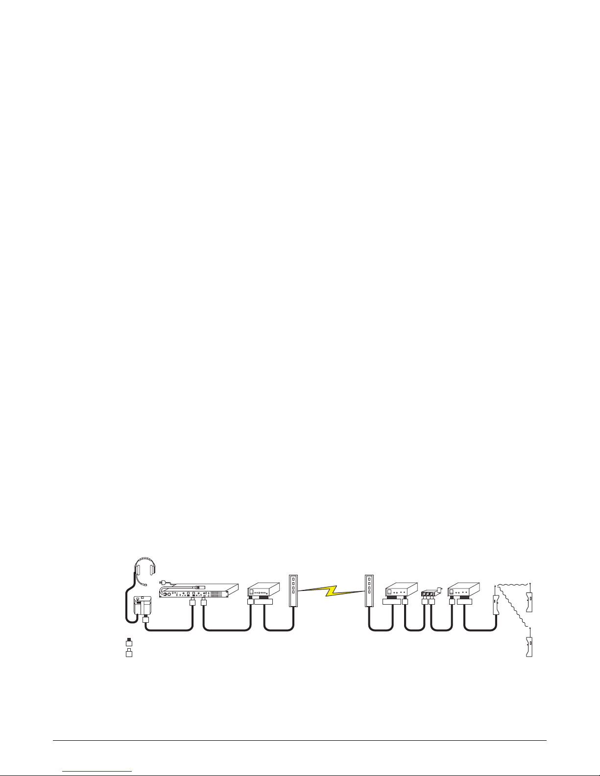
party-line (PL) system connected to a fiber-optic system over a 1-kilometer fiber as shown
in Figure 3. At the other end of the fiber there is another EF-1M unit and PL system with
walkie-talkies interfaced through a TW-40 Interface. The EF-1M allows the people on
the first PL system to communicate with the people on the walkie-talkies over a kilometer
of fiber, with the call signal determining transmit or receive operation.
Figure 3: Interfacing two party-line systems over a kilometer of fiber
NOTE: The terms modem, codec, and interface all refer to devices that convert one type of
signal for transmission or reception to a different type of signal.
3
3
= Male 3-Pin XLR
= Female 3-Pin XLR
Party-Line Intercom
EF-1M
EF-1MFiber Modems TW-40PK-5
Base
Walkie
Talkie
Remote
Walkie
Talkies
3 3
3
3 DB15 3DB15 3 3 3 DB9
Call signaling can serve
as more than merely a
visual indicator.

EF-1M INTERFACE 2-5
Because of the EF-1M’s low profile and compact size, it can function either as a
stand-alone device, or it can be mounted on utility rack shelves. Up to three units will fit
horizontally in one-rack unit (1RU) of space and will offer sufficient vertical clearance to
accommodate a variety of mounting methods. While the EF-1M may be used as a
single-ended 4-wire-to-party-line interface with excellent results, it is uniquely equipped
to work in point-to-point pairs. Much of the discussion in this manual address the issues
of operation in this latter mode.
Due to the superior nulling capability of the EF-1M, more than a single pair of EF-1M
units can be used to link various locations to a single channel.
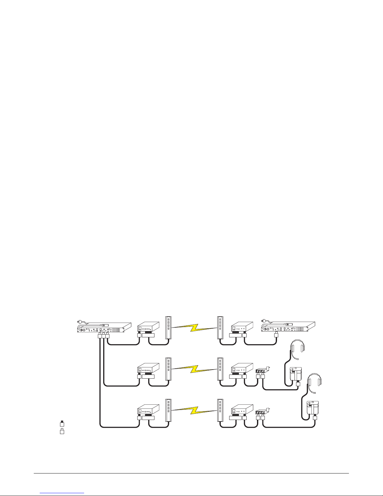
As an example consider the following scenario: The three Channel A ports of an MS-232
main station are each connected to an EF-1M. (For an illustration, see Figure 4.)
Each of those three is in turn connected to a fiber-optic modem and sent through fiber to
another fiber-optic modem, EF-1M unit, and party-line system at the three remote
destinations. All four locations are now sharing the same channel, linked through fiber,
with a total of six “nulls” on the channel. While the nature of 2-wire to 4-wire hybrids
may limit the maximum number of external 2-wire party lines that can be combined, six
EF-1M units on a common channel, properly nulled, should generally provide a stable
system.
Because the EF-1M will be used with a wide variety of third-party systems and devices, it
is not possible to address all the variables of setups and transmission methods. The key
Because of the EF-1M’s
low profile and compact
size, it can function as a
stand-alone device, or it
can be mounted on
utility rack shelves.
2-6 EF-1M INTERFACE
point is that the modem, multiplexer, or converter for the transmission medium (the
system that the EF-1M connects to via the DB-15) must accept line-level (-15 dBV to +4
dBV) 4-wire audio and, if call signal is desired, RS-422 data.
Figure 4: Six EF-1M units link various locations to a single channel
EF-1M
EF-1M
PK-5
3 DB15 3DB15 3 3
EF-1M
EF-1M
PK-5
3 DB15 3DB15
3
3
3
3
= Male 3-Pin XLR
= Female 3-Pin XLR
Party-Line Intercom
EF-1M
EF-1M
Fiber Modems
3
3
3 DB15 3DB15
3
3
3
Party-Line Intercom
3

EF-1M INTERFACE 2-7
FRONT PANEL CONTROLS
Figure 5: Front panel of an EF-1M unit
Local Send controls the audio signal level from the local 2-wire intercom (the system
connected to this EF-1M) to the audio out of the 4-wire I/O. This control has a range of
±12 dB.
Local Receive controls the audio signal level from the audio in of the 4-wire I/O to the
local 2-wire intercom. This control has a range of ±12 dB.
M
You adjust sidetone and
volume “listen levels”
with the EF-1M’s front
panel controls.

2-8 EF-1M INTERFACE
Sidetone Null Adjustment This set of three trimpots includes R=Resistance,
L=Inductance, and C=Capacitance. These compensate for each component of the line
impedance, providing the best null possible. To prevent damage to the level control and
nulling trimpots, do not force them past their stop points.
Power LED This green LED will illuminate when the EF-1M is receiving power from pin
2 of the party-line XLR connection.
Data LED This amber LED has four modes. The first three relate to call signal data.
1. ON- Either a successful data link has been established with a remote EF-1M unit, or
the Matrix Direct mode has been selected at the local EF-1M unit.
2. OFF- There is no data connection at the local EF-1M unit.
3. RAPID BLINK- There is data connection at the local EF-1M unit, but a “break”
condition is present. Depending on the modems used, this can indicate a problem at
the remote end.
4. SLOW BLINK- A test earbud or headphone has been plugged into the test tone jack at
the local EF-1M and the nulling test tone is on.
Call signals will not transmit unless the LED is steadily illuminated. Audio is still
transceived by a connected unit.
EF-1M INTERFACE 2-9
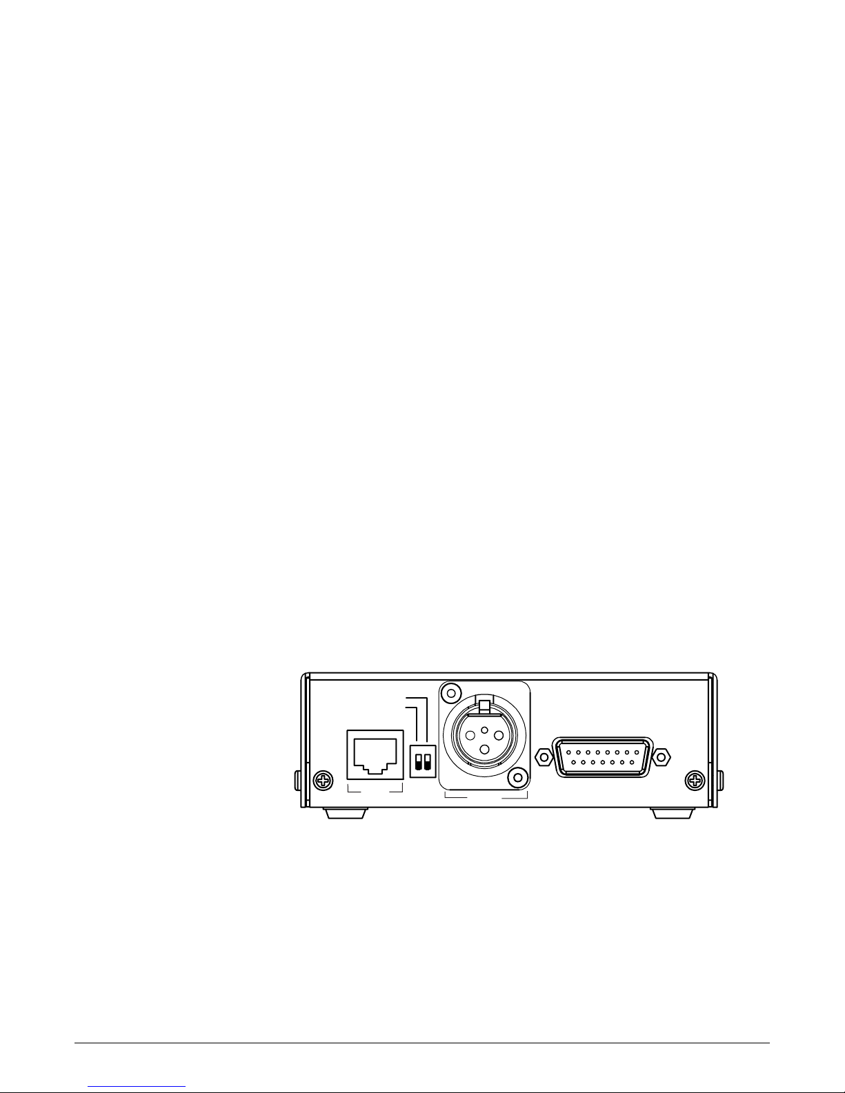
REAR PANEL SETTINGS AND CONNECTORS
Figure 6: Rear panel of an EF-1M unit
Mode-Switch Settings
The two switches on the rear panel of the EF-1M work independently of each other.
Switch 1 adjusts the EF-1M’s connector settings for use with either 4-wire fiber (the ON
position) or a matrix intercom (the OFF position).
Switch 2 adjusts the EF-1M’s connector intercom levels for use with either Clear-Com
equipment (the OFF position) or RTS-TW equipment (the ON position). Table 1
summarizes the mode switch settings.
CC/TW
Matrix Direct
Matrix
Intercom
Call Via
RS-422
Data
4-Wire
Audio
 Loading...