

Page 1

CLEAR-COM ENCORE
PIC-4704, MA-704, AX-704 IFB SYSTEM
INSTRUCTION MANUAL
Page 2

PIC 4704, MA-704, AX-704 IFB System Instruction Manual
© 2007 Vitec Group Communications. All rights reserved.
Part Number 810501Z Rev. 1
Vitec Group Communications, LLC.
850 Marina Village Parkway
Alameda, CA 94501
U.S.A
Vitec Group Communications
7400 Beach Drive
Cambridge Research Park
Cambridgeshire
United Kingdom
CB25 9TP
Vitec Group Communications
Room 1806, Hua Bin Building
No. 8 Yong An Dong Li
Jian Guo Men Wai Ave
Chao Yang District
Beijing, P.R. China 100022
Clear-Com, CellCom/FreeSpeak and the Clear-Com Communication Systems logo are registered trademarks of The Vitec Group
plc.
Page 3

CONTENTS
OPERATION . . . . . . . . . . . . . . . . . . . . . . . . . . . . . . . . . . . . . . . 1-1
Introduction . . . . . . . . . . . . . . . . . . . . . . . . . . . . . . . . . . . . . . . . . . . . . . . . . 1-1
Description . . . . . . . . . . . . . . . . . . . . . . . . . . . . . . . . . . . . . . . . . . . . . . . . . . 1-1
Operation . . . . . . . . . . . . . . . . . . . . . . . . . . . . . . . . . . . . . . . . . . . . . . . . . . . 1-3
INSTALLATION. . . . . . . . . . . . . . . . . . . . . . . . . . . . . . . . . . . . . . 2-1
System Capacity . . . . . . . . . . . . . . . . . . . . . . . . . . . . . . . . . . . . . . . . . . . . . . 2-1
System Architecture. . . . . . . . . . . . . . . . . . . . . . . . . . . . . . . . . . . . . . . . . . . . 2-1
Interconnect Cabling. . . . . . . . . . . . . . . . . . . . . . . . . . . . . . . . . . . . . . . . . . . 2-5
System Connection . . . . . . . . . . . . . . . . . . . . . . . . . . . . . . . . . . . . . . . . . . . . 2-6
Physical Mounting. . . . . . . . . . . . . . . . . . . . . . . . . . . . . . . . . . . . . . . . . . . . . 2-8
Setup and System Check . . . . . . . . . . . . . . . . . . . . . . . . . . . . . . . . . . . . . . . 2-10
MAINTENANCE . . . . . . . . . . . . . . . . . . . . . . . . . . . . . . . . . . . . . 3-1
Troubleshooting Tips. . . . . . . . . . . . . . . . . . . . . . . . . . . . . . . . . . . . . . . . . . . 3-2
SPECIFICATIONS. . . . . . . . . . . . . . . . . . . . . . . . . . . . . . . . . . . . . 4-1
PIC-4704, AX-704 and MA-704 Technical Specifications. . . . . . . . . . . . . . . 4-1
LIMITED WARRANTY . . . . . . . . . . . . . . . . . . . . . . . . . . . . . . . . . . .5-I
Warranty Period. . . . . . . . . . . . . . . . . . . . . . . . . . . . . . . . . . . . . . . . . . . . . . . 5-i
Technical Support . . . . . . . . . . . . . . . . . . . . . . . . . . . . . . . . . . . . . . . . . . . . . 5-i
Warranty Repairs and Returns. . . . . . . . . . . . . . . . . . . . . . . . . . . . . . . . . . . . 5-ii
Non-Warranty Repairs and Returns. . . . . . . . . . . . . . . . . . . . . . . . . . . . . . . . 5-ii
Extended Warranty . . . . . . . . . . . . . . . . . . . . . . . . . . . . . . . . . . . . . . . . . . . . 5-ii
Liability. . . . . . . . . . . . . . . . . . . . . . . . . . . . . . . . . . . . . . . . . . . . . . . . . . . . 5-iii
PIC-4704, MA-704 & AX-704 IFB SYSTEM
i
Page 4

ii
PIC-4704, MA-704 & AX-704 IFB SYSTEM
Page 5

Please read and follow these
instructions before operating
this product.
IMPORTANT SAFETY INSTRUCTIONS
1. Read these instructions.
2. Keep these instructions.
3. Heed all warnings.
4. Follow all instructions.
5. Do not use this apparatus near water.
6. Clean only with dry cloth.
7. Do not block any ventilation openings. Install in accordance with the
manufacturer’s instructions.
8. Do not install near any heat sources such as radiators, heat registers, stoves,
or other apparatus (including amplifiers) that produce heat.
9. Only use attachments/accessories specified by the manufacturer.
10. Use only with the cart, stand, tripod, bracket, or table specified by the
manufacturer, or sold with the apparatus. When a cart is used, use caution
when moving the cart/apparatus combination to avoid injury from tip-over.
11. Unplug this apparatus during lightning storms or when unused for long
periods of time.
12. Refer all servicing to qualified service personnel. Servicing is required when
the apparatus has been damaged in any way, such as power-supply cord or
plug is damaged, liquid has been spilled or objects have fallen into the
apparatus, the apparatus has been exposed to rain or moisture, does not
operate normally, or has been dropped.
13. WA RN I NG : To reduce the risk of fire or electric shock, do not expose this
product to rain or moisture.
Please familiarize yourself with the safety symbols in Figure 1. When you see
these symbols on this product, they warn you of the potential danger of electric
shock if the station is used improperly. They also refer you to important
operating and maintenance instructions in the manual.
PIC-4704, MA-704 & AX-704 IFB System
iii
Page 6
CAUTION
RISK OF ELECTRIC SHOCK
DO NOT OPEN
This symbol alerts you to the presence of uninsulated dangerous
voltage within the product's enclosure that might be of sufficient
magnitude to constitute a risk of electric shock. Do not open
the product's case.
This symbol informs you that important operating and maintenance instructions are included in the literature accompanying
this product.
Figure 1: Safety Symbols
EMC AND SAFETY
The PIC-4704, MA-704 and AX-704 products meet all relevant CE and FCC
specifications set out below:
EN55103-1 Electromagnetic compatibility. Product family standard for audio,
video, audio-visual, and entertainment lighting control apparatus for
professional use. Part 1: Emissions.
EN55103-2 Electromagnetic compatibility. Product family standard for audio,
video, audio-visual, and entertainment lighting control apparatus for
professional use. Part 2: Immunity.
And thereby compliance with the requirement of Electromagnetic
Compatibility Directive 2004/108/EC and Low Voltage Directive 2006/95/EC
This device complies with Part 15 of the FCC Rules. Operation is subject to
the following two conditions: (1) this device may not cause harmful
interference, and (2) this device must accept any interference received,
including interference that may cause undesired operation.
iv
PIC-4704, MA-704 & AX-704 IFB System
Page 7
1
OPERATION
INTRODUCTION
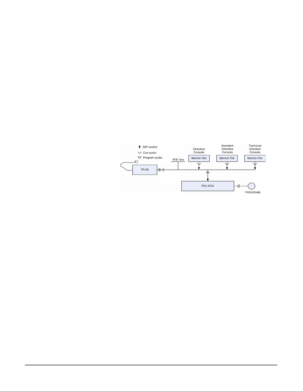
During the production of a program for transmission or recording, a director or
producer frequently needs to cue the performing talent. This is done using
Interrupt FoldBack (IFB), a type of closed-circuit intercom for sending program
and cue audio on “IFB” lines for the talent to monitor. The IFB line carries three
signals: program audio, cue audio, and the dip or mute control. See the signal
flow diagram below (Figure 1-1). Electronic control allows the director to
interrupt the program signal when addressing the talent. IFB communications
are one-way only from an access location to the selected talent position.
Figure 1-1: Audio Control Paths
Clear-Com’s new stand-alone IFB components provide high performance,
cost-effective answers for applications where regular intercom functions are not
also required, or where space contraints require compact, versatile packaging.
The simplest stand-alone system consists of a PIC-4704, an MA-704, a PS-702
for power, and one to four TR-50 talent receivers. This system will permit cuing
of one to four talent positions from only one access location.
Note: Throughout this manual, “access location” refers to the physical place
someone needs to cue the talent from. “Talent position” refers to the
individual “talent” cue channels.
DESCRIPTION
Clear-Com’s stand-alone series of IFB components offers two types of talent
access station. The MA-704 has a socket for a gooseneck microphone and a
pre-amplifier with line-level output. It provides access to four talent positions.
Each AX-704 allows access, from the same location, to an additional group of
four talent positions; it requires an external line-level signal for its cue audio
source. The MA-704’s cue audio and ALL control signals will feed up to 24
AX-704s, so that only one MA-704 is required at each access location. Each talent
position may be accessed independently, or simultaneously with any other(s).
The ALL button on the MA-704 simultaneously accesses all talent positions of
the MA-704 and each AX-704 extension unit fed from that MA-704.
PIC-4704, MA-704 & AX-704 IFB SYSTEM
1-1
Page 8
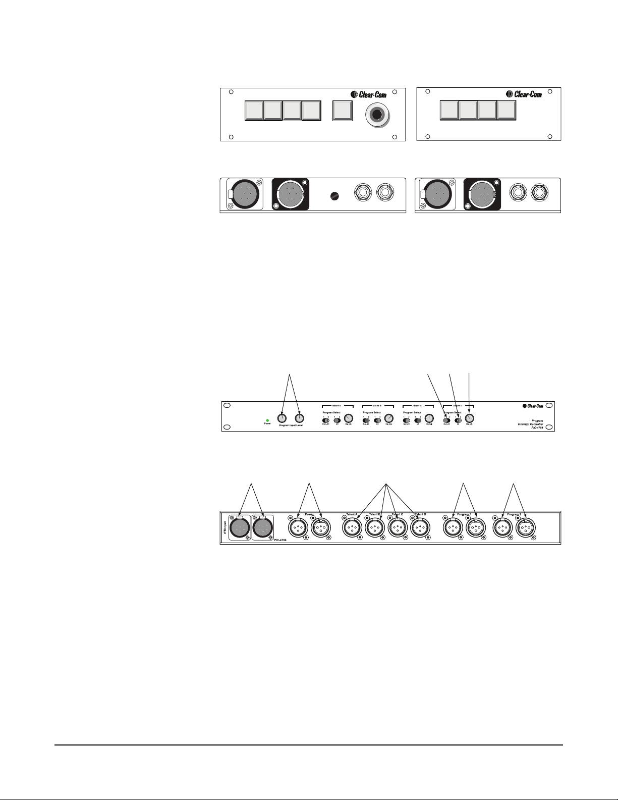
AX-704
All
MA-704
AX-704
IFB Input
The MA-704 The AX-704
Mic Gain
IFB Extension
Exten. Bus
Out
External Line
In
IFB Input
Exten. Bus
IFB Extension
Out
External Line
In
Figure 1-2: MA-704 and AX-704 Units
A PIC-4704 unit is required for every four talent positions, or fraction thereof.
For example, a system with five to eight talent positions will require two
PIC-4704s. The same IFB system with three access locations will require three
MA-704s and three AX-704s, but will still need only two PIC-4704s. The
PIC-4704 performs the program feed and interrupt functions for each talent
position, and also terminates the IFB lines.
1
5
6
7
2
4
3
8
9
1-2
Figure 1-3: PIC-4704 Controls and Connectors
The PIC-4704 controls and connectors shown in Figure 1-3 are:
1. Program input level adjustment
2. Selector for non-interruptible program feed
3. Selector for interruptible program feed
4. Audio dip adjustment control
5. IFB inputs
6. Connectors to power supply (station or power supply)
7. Outputs to talent receivers
8. Program 1 loop through
9. Program 2 loop through
PIC-4704, MA-704 & AX-704 IFB SYSTEM
Page 9

The connectors on the MA-704, AX-704, and PIC-4704 are arranged for
convenient interconnection as a stand-alone system. However, all the units’
electrical characteristics are identical to those of the integrated IFB systems on
our standard broadcast intercom line. With suitable connector adaptors, both
types of units can be mixed in a system.
OPERATION
The system is operated by engaging the desired cue buttons on the access
stations. A control voltage on the IFB line causes the PIC-4704 to dip the
program feed to that channel so that the cues given are understandable. (At an
optional split-feed receiver, the program is dipped only in the cue side; the other
side has continuous program with no cue.)
1. Press the IFB button on the access station corresponding to the talent position(s) you wish to cue, then speak into the MA-704’s microphone.
2. Press the MA-704’s ‘All’ button and you simultaneously activate every IFB line, including those on any accompanying AX-704 units.
The control voltage also causes the corresponding buttons at all other access
locations to change in color from blue to amber, indicating which channels are in
use.
PIC-4704, MA-704 & AX-704 IFB SYSTEM
1-3
Page 10

1-4
PIC-4704, MA-704 & AX-704 IFB SYSTEM
Page 11

2
INSTALLATION
SYSTEM CAPACITY
A system may have up to fifty access locations. Cue audio from the MA-704 can
drive up to twenty-three AX-704 units, thus permitting a maximum of ninety-six
talent positions.
In order to use the IFB system at its maximum capacity, two factors must be
considered: system wiring (architecture) and power requirements. The MA-704
consumes a maximum of 180 mA (idle current 140 mA), and the AX-704
consumes a maximum of 150 mA (idle current 120 mA). Since the resistance of
the conductors in the interconnect cable may be on the order of five to ten Ohms
per 1000 feet, care must be taken to avoid having too many stations on one long
cable run.
For example, a system with two MA-704s on a 2000 foot cable which has 16
Ohms cumulative resistance in the power conductor, plus another 10 Ohms in
the common conductor, the voltage drop is a maximum of 9 volts. If another two
MA-704s were to be added for the same cable run, the voltage drop would be an
unacceptable 18 volts. Therefore, the other set of access stations would have to be
connected on separate cable run from the PIC-4704.
To determine the number and type of power supplies a system requires, add up
the number of Unit Loads (1 Unit Load=50 mA).
• PIC-4704=2 Unit Loads
• Four TR-50s=1 Unit Load
• MA-704=4 Unit Loads
• AX-704=3 Unit Loads
A PS-702 has enough capacity for 24 unit loads.
SYSTEM ARCHITECTURE
Two basic cabling methods for connecting the system may be used: “daisy-chain”
(or loop-through) and “hub.” Both methods may be combined in any system.
Since the PIC-4704 has only two IFB line connectors, a hub-type system is
limited to two branches unless a special splitter box is used. Generally,
resistance-buildup effects and resultant voltage drop are worse when using the
daisy-chain approach. The hub approach minimizes voltage-drop effects at the
expense of greater cumulative cable capacitance. Cable capacitance is not quite
the problem it is in regular intercom systems, because there is no sidetone null
change, only a degradation of high-frequency response.
PIC-4704, MA-704 & AX-704 IFB SYSTEM
2-1
Page 12

Referring to the typical system block diagrams shown below, only the system in
Figure 2-2 is connected using the “hub” method; all other systems are shown
connected via the “daisy-chain” method.
Figure 2-1: One Access Location to up to Four Talent Positions
2-2
Figure 2-2: Two Access Locations to up to Four Talent Positions
PIC-4704, MA-704 & AX-704 IFB SYSTEM
Page 13

Figure 2-3: Three Access Locations to up to Four Talent Positions
Figure 2-4: One Access Location to up to Eight Talent Positions
PIC-4704, MA-704 & AX-704 IFB SYSTEM
2-3
Page 14
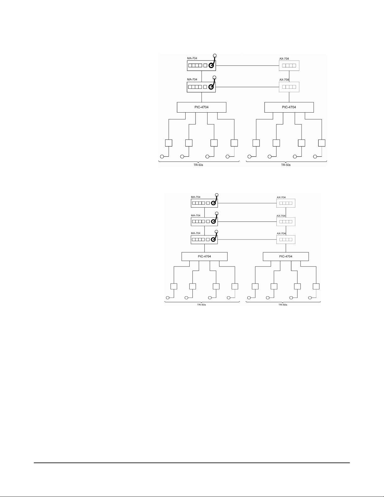
Figure 2-5: Two Access Locations to up to Eight Talent Positions
Figure 2-6: Two Access Locations to up to Eight Talent Positions
2-4
PIC-4704, MA-704 & AX-704 IFB SYSTEM
Page 15

INTERCONNECT CABLING
Use one multi-pair cable for each group of four channels when connecting the
IFB lines between the access stations and their associated component (other
MA-704s or AX-704s and the PIC-4704). This cable must have (four) separately
shielded conductors or pairs of conductors to prevent crosstalk. Suitable cable
types are: Alpha #6054, Belden #8725 or 9330, and Mogami #2602. As noted in
the previous section, the resistance buildup in both the power and common (or
ground) conductors must be kept at a minimum for proper operation. Resistance
buildup in the common conductor will also increase crosstalk. Follow the
diagram below for best results in connecting the cable to the XLR connectors.
Notice that all four of the spare conductors in each pair are tied together to pin 2
(DC power), and all shields are tied together to pin 1 (common). This
arrangement minimizes resistance buildup effects in long cable runs.
Clear-Com has ready-made cable in 25, 50, and 100 foot lengths to fit your
cabling and system architecture needs.
Figure 2-7: XLR6 Cable Wiring
In a system with more than four talent positions (one group), the cue audio from
the MA-704’s mic preamp and the ALL control signal must be bussed from the
MA-704 to each AX-704 unit. A two-conductor shielded mic cable with
1/4-inch TRS phone plugs at each end is used for this purpose. Refer to Figure
2-8 for pinout details.
Note: The diagram shows the access stations for talent positions 5–8 connected in
a “hub” from the second PIC-4704 while the stations for the first group of
talent positions (1–4) are shown connected in the “daisy-chain” method. In
practice, stations for both groups of talents would be interconnected in the
same manner.
Connect single channel talent receivers to the PIC-4704 using standard
two-conductor mic cable. Only two conductors are necessary for cabling between
the power supply and the PIC-4704(s). If any section of this cable is more than a
few feet long, be sure that heavy-guage wire is used.
PIC-4704, MA-704 & AX-704 IFB SYSTEM
2-5
Page 16

SYSTEM CONNECTION
1. Determine the architecture for your IFB system.
2. Decide upon a location for the PIC-4704(s).
3. Connect the PIC-4704(s) to Clear-Com power supply(s) such as the PS-702 or PS-704.
4. Connect the program sources(s) to the PIC-4704(s) as required. A balanced
program source is connected to pins 2 and 3 of the program input. The
common pin can be connected to the common or ground point of the
source, if necessary, to eliminate any residual hum. If a single-ended source is
used, either pin 2 or 3 must be connected to the common point of the
source. The “high” side is connected to the other pin (2 or 3).
5. Use standard multi-pair shielded cables and two-conductor shielded mic cables to interconnect the access stations as described in the preceding section.
6. Route all cables from the access locations and the talent receivers to the
PIC-4704(s) using either or both of the methods discussed in the previous
section. Pin assignments for the rear panel IFB XLR connectors are: Pin 1,
Common; Pin 2, power; Pins 3–6, talent channels 1–4 respectively.
7. Route cables away from heavy AC power sources such as lighting panels or electric motors.
8. In permanent installations, cables should be installed in accordance with approved local building codes.
2-6
PIC-4704, MA-704 & AX-704 IFB SYSTEM
Page 17

PIC-4704 #2
(Talent Positions 5, 6, 7, 8)
TR-50
Talent Position 8
TR-50
Talent Position 6
PS-702 Power Supply
Source
Program
PROGRAM INPUT
AUDIO
ADJUST
ON
B
TERM
OFF
TR-50
Talent Position 4
INTERCOM CHANNEL B
3 Pin - 3 Wire
Pin 1 - Common
Pin 2 V+
Pin 3 - Audio
ON
A
PIC-4704 #1
TERM
OFF
TR-50
Talent Position 3
TR-50
Talent Position 2
(Talent Positions 1, 2, 3, 4)
INTERCOM CHANNEL A
AX-704
(Talent Positions 6 & 8)
MA-704
(Tech. Director)
Access Location #2
(Talent Positions 1, 2,3, 4)
3 Pin - 2 Wire
Pin 1 - Common
Pin 2 - V+
Pin 3 - N/C
In
External Line
Out
Exten. Bus
IFB Extension
IFB Input
In
External Line
Out
Exten. Bus
Mic Gain
IFB Extension
IFB Input
PS-702
65 W(MAX)
AX-704
MA-704
(Director)
Access Location #1
In
External Line
Out
Exten. Bus
IFB Extension
(Talent Positions 6 & 8)
IFB Input
In
External Line
Out
Exten. Bus
Mic Gain
IFB Extension
(Talent Positions 1, 2, 3, 4)
IFB Input
6 Pin - 6 Wire
Pin 1 - Common
Pin 2 - V+
Pin 3 - CH. A
Phone Jack
Tip - Conductor A
Ring - Conductor B
Sleeve - Shield
Pin 4 - CH. B
Pin 5 - CH. C
Pin 6 - CH. D
TR-50
Talent Position 1
PIC-4704, MA-704 & AX-704 IFB SYSTEM
Figure 2-8: IFB Wiring Example
2-7
Page 18

PHYSICAL MOUNTING
The PIC-4704 is designed for mounting in a standard 19-inch rack. It requires
only one 1.75-inch rack space, and is 7.5-inches deep.
The MA-704 and AX-704 may be mounted in a console or desk, or in a standard
19-inch rack using the optional model CEP-RK rack kit. Refer to the diagrams
below for mounting dimensions when installing in a desk or console. There are
no special constraints on relative positioning of MAs and AXs, though it is
expected that the extension bus cable (the one with phone plugs) will be no more
than 10 feet (normally 18 inches long). Be sure to make allowance for the XLR
connectors to be plugged into the back of each access station.
2-8
Figure 2-9: MA-704 Mounting Dimensions
PIC-4704, MA-704 & AX-704 IFB SYSTEM
Page 19

Figure 2-10: AX-704 Mounting Dimensions
PIC-4704, MA-704 & AX-704 IFB SYSTEM
2-9
Page 20

SETUP AND SYSTEM CHECK
After program sources are connected, assign them at the PIC-4704 to the talent
channels with the Program (Source) select switches for each channel’s interrupt
and non-interrupt talent feeds (see Figure 1-3). Set the switch left to select source
1 or right to select source 2.
Set the attenuation or dip of the program feed during cuing with the dip
adjustment trims (see Figure 1-3). They can be set from no attenuation (fully
CW) to greater than 50 dB (fully CCW).
Before adjusting the Program Level trims at the PIC-4704, the volume at the
Talent Receivers must be adjusted (via the control on the Receiver) for a
comfortable cue audio level in the earpiece or headset while someone is cuing
that talent position from one of the access locations.
The Program Input Level controls permit use of program levels ranging from –20
dBu to 0 dBu. At full clockwise rotation, the gain from program input to the IFB
line is approximately unity. So at maximum gain setting, a program level of –20
dBu will be roughly the same volume on the IFB line as the cue audio. If the
program source level is around 0 dBu, the controls will have to be set near full
counter-clockwise rotation to match the cue audio level on the IFB lines.
The only adjustment possible at the MA-704 is a trim (± 5 dB) of the mic gain.
Adjusting this gain should be necessary only in unusual circumstances, because of
the mic preamp’s limiter.
2-10
PIC-4704, MA-704 & AX-704 IFB SYSTEM
Page 21

3
MAINTENANCE
The table of possible problems on the next page, which generally involves system
wiring, covers only the most likely problems. In any troubleshooting effort, keep
these points in mind:
1. The power for all units in the system is routed from the power supplies
through the PIC-4704.
2. All access stations (MAs and AXs) and the talent receivers are connected across
the IFB lines in a bridging configuration (high impedance).
3. Each IFB line is terminated by its associated PIC-4704. The termination is
about 220 Ohms AC, and approximately 5,000 Ohms DC.
4. Three different types of signals are present on the IFB line:
a. Cue audio, which originates from an access station’s microphone.
b. Program audio, from the associated PIC-4704.
c. Interrupt control signal, a DC voltage which also originates at an access
station.
5. The cue audio and all control signals for operation of the AX-704 stations at
any given location are supplied by the MA-704 station at that location.
PIC-4704, MA-704 & AX-704 IFB SYSTEM
3-1
Page 22

TROUBLESHOOTING TIPS
SYMPTOM CAUSE SOLUTION
Channel access
button not lit or
too dim.
Access button
won’t light amber
when engaged at
any station.
Access button
remains lit in
amber after being
released.
No cue from an
AX-704 station.
(a) No power.
(b) Insufficient power
(a) Excessive DC load
on affected IFB line.
(b) IFB line shorted in
cabling.
IFB line not
termintated.
(a) Associated
MA-704 not
operating.
(a) Check that power
supply is operating
and connected to the
PIC-4704
(b) Increase power
capacity or connect
fewer stations on each
cable run.
(a) Isolate and replace
faulty module on
affected line.
(b) Isolate and repair
cable.
Insure that station
connections to
PIC-4704 are intact.
(a) Insure that
MA-704 is connected
to a PIC-4704.
Hum or buzz from
program. (program
control affects
loudness)
(b) Faulty or missing
connection to
MA-704 or AX-704
unit.
Mis-connection of
program source to
output.
(b) Verify connection
of extension bus to
affected AX-704 unit.
Program inputs are
balanced. If
single-ended source is
used, one of inputs
must be referenced to
common.
3-2
PIC-4704, MA-704 & AX-704 IFB SYSTEM
Page 23

4
SPECIFICATIONS
PIC-4704, AX-704 AND MA-704 TECHNICAL SPECIFICATIONS
dBu is an absolute measurement. 0 dBu is referenced to 0.775 V RMS.
Panel Microphone Input (MA-704)
Input Type Electret
Input Impedance >=2K
Mic Limiter Threshold 0dB ± 3dB
Mic Limiter Range >= 15dB
Program Line Input
Maximum Level before Clipping >= 20dBu
Input Impedance >= 5K
Frequency Response
Panel Mic - Talent (MA-704 only) 200 - 18KHz ± 3dB
Program Input - Talent 200 - 18KHz ± 3dB
Extension Line - Talent 200 - 18KHz ± 3dB
Ω
Ω
Max Distortion
Panel Mic - Talent (MA-704 only) <= 0.5%
Program Input - Talent <= 0.1%
Extension Line - Talent <= 0.1%
Noise
Panel Mic - Talent (MA-704 only) < -65dBu
Program Input - Talent < -85dBu
Extension Line - Talent < -85dBu
Max Gain
Panel Mic - Talent (MA-704 only) >= 30dB
Program Input - Talent >= -14dB
Extension Line - Talent -14dB ± 3dB
Min Gain
Panel Mic - Talent (MA-704 only) <= 40dB
Program Input - Talent <= -45dB
Power (PIC-4704)
Input Voltage Range 20-30 VDC
Input Current <= 90mA
PIC-4704, MA-704 & AX-704 IFB SYSTEM
4-1
Page 24

Power (MA-704)
Input Voltage Range 20-30 VDC
Input Current (Idle) <= 140mA
Input Current (Max) <= 180mA
Power (AX-704)
Input Voltage Range 20-30 VDC
Input Current (Idle) <= 120mA
Input Current (Max) <= 150mA
Rear Panel Connectors (PIC-4704)
IFB Input (2) XLR6F
Power In (1) XLR3F
Power Out (1) XLR3M
Talent Out (4) XLR3M
Program In (2) XLR3F
Program Out (2) XLR3M
Rear Panel Connectors and Controls (MA-704)
IFB Input (1) XLR6F
IFB Extension (1) XLR6M
Extension Bus Out (1) ¼” jack
External Line In (1) ¼ jack
Mic Gain (1) Gain adjust
Rear Panel Connectors and Controls (AX-704)
IFB Input (1) XLR6F
IFB Extension (1) XLR6M
Extension Bus Out (1) ¼” jack socket
External Line In (1) ¼ jack socket
Front Panel Controls & Indicators (PIC-4704)
(1) Power indicator LED
(2) Program input level controls
(4) Non-interrupt program select
switches
(4) Interrupt program select switches
(4) Audio dip level controls
Front Panel Controls & Indicators (MA-704)
(5) Talk buttons
(1) ¼” microphone jack socket
Front Panel Controls & Indicators (AX-704)
(4) Talk buttons
Environmental
32 - 122o F (0 - 50o C)
4-2
PIC-4704, MA-704 & AX-704 IFB SYSTEM
Page 25

Dimensions (H x W x D)
PIC-4704 1.75 in. x 19 in. x 7.5 in.
MA-704 1.75 in. x 6.3 in. x 5.5 in.
AX-704 1.75 in. x 4.9 in. x 5.5 in.
Weight
PIC-4704 5.76 lbs. (2.62 kg)
MA-704 1.71 lbs. (.78kg)
AX-704 1.35 lbs. (.61 kg)
Notice About Specifications
While Clear-Com makes every attempt to maintain the accuracy of the
information contained in its product manuals, that information is subject to
change without notice. Performance specifications included in this manual are
design-center specifications and are included for customer guidance and to
facilitate system installation. Actual operating performance may vary.
PIC-4704, MA-704 & AX-704 IFB SYSTEM
4-3
Page 26

4-4
PIC-4704, MA-704 & AX-704 IFB SYSTEM
Page 27

LIMITED WARRANTY
Vitec Group Communications (VGC) warrants that at the time of purchase, the
equipment supplied complies with any specification in the order confirmation
when used under normal conditions, and is free from defects in workmanship
and materials during the warranty period.
During the warranty period VGC, or any service company authorized by VGC,
will in a commercially reasonable time remedy defects in materials, design, and
workmanship free of charge by repairing, or should VGC in its discretion deem it
necessary, replacing the product in accordance with this limited warranty. In no
event will VGC be responsible for incidental, consequential, or special loss or
damage, however caused.
WARRANTY PERIOD
Return Material
Authorization (RMA)
numbers are required for all
returns.
Both warranty and
non-warranty repairs are
available.
The product may consist of several parts, each covered by a different warranty
period. The warranty periods are:
• Cables, accessories, components, and consumable items have a limited
warranty of 90 days.
• Headsets, handsets, microphones, and spare parts have a limited warranty of
one year.
• UHF wireless IFB products have a limited warranty of one year.
• UHF wireless intercom systems have a limited warranty of three years.
• All other Clear-Com and Drake brand systems and products, including
beltpacks, have a limited warranty of two years.
The warranty starts at the time of the product’s original purchase. The warranty
start date for contracts which include installation and commissioning will
commence from the earlier of date of the Site Acceptance Test or three months
from purchase.
TECHNICAL SUPPORT
To ensure complete and timely support to its customers, VGC’s User Support
Center is staffed by qualified technical personnel. Telephone and email technical
support is offered worldwide by the User Support Center.
The User Support Center is available to VGC’s customers during the full course
of their warranty period.
Instructions for reaching VGC’s User Support Centers are given below.
Telephone for Europe, Middle East and Africa: +49 40 6688 4040 or +44 1223
815000
WARRANTY
i
Page 28

Telephone for the Americas and Asia: +1 510 337 6600
Email: vitec.support@AVC.de
Once the standard warranty period has expired, the User Support Center will
continue to provide telephone support if you have purchased an Extended
Warr an ty.
For latest contact information please refer to the Service and Support section at
www.clearcom.com.
WARRANTY REPAIRS AND RETURNS
Before returning equipment for repair, contact a User Support Center to obtain a
Return Material Authorization (RMA). VGC representatives will give you
instructions and addresses for returning your equipment. You must ship the
equipment at your expense, and the support center will return the equipment at
VGC’s expense.
For out-of-box failures, use the following contact information:
Europe, Middle East and Africa
Tel: +44 1223 815000 Email: customerservicesEMEA@vitecgroup.com
North America, Canada, Mexico, Caribbean & US Military
Tel: +1 510 337 6600 Email: customerservicesUS@vitecgroup.com
Asia Pacific & South America
Tel: +1 510 337 6600 Email: customerservicesAPAC@vitecgroup.com
VGC has the right to inspect the equipment and/or installation or relevant
packaging.
For latest contact information please refer to the Service and Support section at
www.clearcom.com.
NON-WARRANTY REPAIRS AND RETURNS
For items not under warranty, you must obtain an RMA by contacting the User
Support Center. VGC representatives will give you instructions and addresses for
returning your equipment.
You must pay all charges to have the equipment shipped to the support center
and returned to you, in addition to the costs of the repair.
EXTENDED WARRANTY
You can purchase an extended warranty at the time of purchase or at any time
during the first two years of ownership of the product. The purchase of an
extended warranty extends to five years the warranty of any product offered with
a standard two-year warranty. The total warranty period will not extend beyond
five years.
ii
WARRANTY
Page 29

Note: VGC does not offer warranty extensions on UHF wireless intercom
systems, or on any product with a 1-year or 90-day warranty.
LIABILITY
THE FOREGOING WARRANTY IS VGC'S SOLE AND EXCLUSIVE
WARRANTY. THE IMPLIED WARRANTY OF MERCHANTABILITY
AND FITNESS FOR A PARTICULAR PURPOSE AND ANY OTHER
REQUIRED IMPLIED WARRANTY SHALL EXPIRE AT THE END OF
THE WARRANTY PERIOD. THERE ARE NO OTHER WARRANTIES
(INCLUDING WITHOUT LIMITATION WARRANTIES FOR
CONSUMABLES AND OTHER SUPPLIES) OF ANY NATURE
WHATSOEVER, WHETHER ARISING IN CONTRACT, TORT,
NEGLIGENCE OF ANY DEGREE, STRICT LIABILITY OR OTHERWISE,
WITH RESPECT TO THE PRODUCTS OR ANY PART THEREOF
DELIVERED HEREUNDER, OR FOR ANY DAMAGES AND/OR LOSSES
(INCLUDING LOSS OF USE, REVENUE, AND/OR PROFITS). SOME
STATES DO NOT ALLOW THE EXCLUSION OR LIMITATION OF
INCIDENTAL OR CONSEQUENTIAL DAMAGES OR THE
LIMITATION ON HOW LONG AN IMPLIED WARRANTY LASTS, SO
THE ABOVE LIMITATIONS MAY NOT APPLY TO YOU. IN ANY
EVENT, TO THE MAXIMUM EXTENT PERMITTED UNDER
APPLICABLE LAW, VGC'S LIABILITY TO CUSTOMER HEREUNDER
SHALL NOT UNDER ANY CIRCUMSTANCES EXCEED THE COST OF
REPAIRING OR REPLACING ANY PART(S) FOUND TO BE
DEFECTIVE WITHIN THE WARRANTY PERIOD AS AFORESAID.
This warranty does not cover any damage to a product resulting from cause other
than part defect and malfunction. The VGC warranty does not cover any defect,
malfunction, or failure caused beyond the control of VGC, including
unreasonable or negligent operation, abuse, accident, failure to follow
instructions in the manual, defective or improperly associated equipment,
attempts at modification and repair not approved by VGC, and shipping
damage. Products with their serial numbers removed or defaced are not covered
by this warranty.
This warranty does not include defects arising from installation (when not
performed by VGC), lightning, power outages and fluctuations, air conditioning
failure, improper integration with non-approved components, defects or failures
of customer furnished components resulting in damage to VGC provided
product.
This limited warranty is not transferable and cannot be enforced by anyone other
than the original consumer purchaser.
This warranty gives you specific legal rights and you may have other rights which
vary from country to country.
WARRANTY
iii
Page 30

iv
WARRANTY
 Loading...