

Page 1
FreeSpeak II® Integra
Eclipse HX 8.5.2 and above
Part Number: 399G177 Rev B
Date: October 11, 2017
User
Guide
Page 2

User Guide| FreeSpeak II® Integra (Matrix version)
Page 2
Document Reference
Clear-Com FreeSpeak II User Guide
Part Number: 399G177 Revision: B
Legal Disclaimers
Copyright © 2017 HME Clear-Com Ltd.
All rights reserved.
Clear-Com and the Clear-Com logo are registered trademarks of HM Electronics,
Inc.
The software described in this document is furnished under a license agreement
and may be used only in accordance with the terms of the agreement.
The product described in this document is distributed under licenses restricting its
use, copying, distribution, and decompilation/reverse engineering. No part of this
document may be reproduced in any form by any means without prior written
authorization of Clear-Com, an HME Company.
Clear-Com Offices are located in California, USA; Cambridge, UK; Dubai, UAE;
Montreal, Canada; and Beijing, China. Specific addresses and contact information
can be found on Clear-Com’s corporate website:
www.clearcom.com
Clear-Com Contacts
Americas and Asia-Pacific Headquarters
California, United States
Tel: +1.510.337.6600
Email: CustomerServicesUS@clearcom.com
Europe, Middle East, and Africa Headquarters
Cambridge, United Kingdom
Tel: +44 1223 815000
Email: SalesSupportEMEA@clearcom.com
China Office
Beijing Representative Office
Beijing, P.R.China
Tel: +8610 65811360 / 65815577
Page 3

User Guide| FreeSpeak II® Integra (Matrix version)
Page 3
Contents
FreeSpeak II® Integra ............................................................... 1
Eclipse HX 8.5.2 Version ................................................................ 1
Document Reference ..................................................................... 2
1 Important Safety instructions ..................................... 7
1.1 Safety symbols .............................................................. 8
2 Introduction to FreeSpeak II® ..................................... 9
2.1 An FS II communication system ........................................ 9
2.1.1 FreeSpeak II system capacity ........................................... 11
2.1.2 National Radio Carrier Frequencies .................................... 12
2.1.3 FSII 1.9 GHz/FSII 2.4 GHz ............................................... 12
3 Installing a system .................................................... 13
3.1 Adding the E-Que card for an FS II antenna or splitter to the
matrix ......................................................................... 13
3.1.1 Installing and removing an E-Que card. .............................. 13
3.1.2 Adding an E-Que card to the software ................................ 14
3.2 Placing the antennas and splitters ................................... 15
3.2.1 Wiring the antennas and splitters ...................................... 16
3.3 Connecting to transceiver/antennas ................................ 17
3.3.1 Connecting one transceiver/antenna directly to a transceiver
port .............................................................................. 17
3.3.2 Connecting transceiver/antennas with a splitter (PD2203) ..... 17
3.3.3 Powering an antenna or antenna splitter ............................. 20
3.4 Determining coverage areas ........................................... 21
3.5 Doing a site survey to determine coverage areas .............. 22
3.5.1 Doing a site survey with a beltpack .................................... 22
3.5.2 Testing antenna handoff .................................................. 24
3.5.3 Assigning beltpacks to coverage areas ............................... 25
3.5.4 Conditions affecting coverage areas ................................... 25
3.5.5 Surveying a site in standalone (rigging) mode ..................... 25
3.6 Registering beltpacks .................................................... 27
Page 4

User Guide| FreeSpeak II® Integra (Matrix version)
Page 4
4 Operating the wireless beltpack ................................ 28
4.1 Overview of the wireless beltpack ................................... 28
4.2 Beltpack user controls ................................................... 31
4.2.1 Top controls ................................................................... 31
4.2.2 Beltpack display .............................................................. 32
4.2.3 Beltpack headset tones/alerts ........................................... 32
4.2.4 Front controls ................................................................. 34
4.2.5 Beltpack bottom connectors .............................................. 35
4.2.6 Beltpack rear panel ......................................................... 37
4.3 Using the beltpack ........................................................ 37
4.3.1 Registering the beltpack ................................................... 37
4.3.2 Charging the beltpack ...................................................... 38
4.3.3 How to set AA battery type: Nickel-metal hydride (NiMHi) or
Alkaline for wireless beltpacks ........................................... 39
4.3.4 Powering on the beltpack ................................................. 40
4.3.5 Using the beltpack to communicate ................................... 40
4.3.6 Entering and exiting Menu mode ....................................... 41
4.3.7 Setting and Adjusting Listen Levels .................................... 41
4.3.8 Upgrading beltpack firmware ............................................ 42
5 Programming on the beltpack ................................... 44
5.1 Introduction to programming on the beltpack ................... 44
5.2 Configuring the beltpack volume settings ......................... 45
5.2.1 Configuring the beltpack channel volumes and master volume
.................................................................................... 46
5.2.2 Configuring the volume level of the line input ...................... 46
5.2.3 Configuring the rotary controls .......................................... 46
5.3 Configuring the beltpack headset .................................... 47
5.3.1 Setting headset autodetect ............................................... 47
5.3.2 Setting the sidetone level ................................................. 48
5.3.3 Setting the headset limiter ............................................... 48
5.4 Configuring the beltpack microphone ............................... 48
5.4.1 Setting the microphone type ............................................. 49
5.4.2 Setting the microphone echo cancellation ........................... 49
Page 5

User Guide| FreeSpeak II® Integra (Matrix version)
Page 5
5.5 Configuring the beltpack display and LEDs ....................... 50
5.5.1 Setting the display and LED brightness ............................... 50
5.5.2 Setting the display dim timeout ......................................... 50
5.5.3 Setting the display off timeout .......................................... 51
5.6 Configuring the beltpack alarm options ............................ 51
5.6.1 Setting the low battery alarm ........................................... 51
5.6.2 Setting the low battery alarm threshold .............................. 52
5.6.3 Setting the out of range alarm .......................................... 52
5.6.4 Setting the call alert ........................................................ 53
5.7 Selecting the beltpack role default set ............................. 53
5.8 Selecting the beltpack administration .............................. 54
5.8.1 Enabling OTA registration mode ........................................ 54
5.8.2 Setting full menu access .................................................. 54
5.8.3 Setting system sync mode (not currently available) ............. 55
5.9 Setting the listen again option ........................................ 55
5.10 Control audio on keys C & D (beltpack)(advanced menu
option only) ................................................................. 56
5.11 Accessing beltpack information ....................................... 56
5.12 Setting display mode .................................................... 57
5.13 Setting system connect ................................................. 57
5.14 Enabling over the air (OTA) registration mode from a beltpack
................................................................................. 58
5.15 Performing a site survey ................................................ 59
6 Operating the transceiver/antenna ........................... 60
6.1 Transceiver/antenna ..................................................... 60
6.1.1 IP rating (International Protection Marking) ........................ 60
6.1.2 FS II transceiver/antenna connector panel .......................... 61
6.1.3 Cabling the antennas ....................................................... 62
6.1.4 Beltpack support capacities for transceiver/antennas ............ 66
6.1.5 Coverage areas under various conditions ............................ 66
6.1.6 Transceiver/antenna setup rules and tips ............................ 67
6.1.7 Upgrading antenna firmware ............................................. 67
Page 6

User Guide| FreeSpeak II® Integra (Matrix version)
Page 6
6.2 Transceiver/antenna splitter (PD2203) ............................ 69
6.2.1 PD2203 Front connector panel .......................................... 69
6.2.2 PD2203 rear panel .......................................................... 70
6.2.3 Connecting an antenna splitter to the E-Que-HX card and to
transceiver/antennas ....................................................... 71
7 Beltpack menus ......................................................... 72
7.1 Beltpack menu maps ..................................................... 72
8 Specifications ............................................................ 77
8.1 FreeSpeak II Beltpack ................................................... 77
8.2 FreeSpeak II Transceiver/Antenna .................................. 78
8.3 FreeSpeak II Transceiver/Antenna Splitter ....................... 78
8.4 Transmission Method .................................................... 79
9 Federal Communications Commission (FCC) compliance
.................................................................................. 80
Page 7

User Guide| FreeSpeak II® Integra (Matrix version)
Page 7
1 Important Safety instructions
• Read these instructions.
• Keep these instructions.
• Heed all warnings.
• Follow all instructions.
• Do not use this apparatus near water.
• Clean only with dry cloth.
• Do not block any ventilation openings. Install in accordance with the
manufacturer’s instructions.
• Do not install near any heat sources such as radiators, heat registers,
stoves, or other apparatus (including amplifiers) that produce heat.
• Do not defeat the safety purpose of the polarized or grounding-type plug.
A polarized plug has two blades and a third grounding prong. The wide
blade or the third prong is provided for your safety. If the provided plug
does not fit into your outlet, consult an electrician for replacement of the
obsolete outlet.
• Protect the power cord from being walked on or pinched particularly at
plugs, convenience receptacles, and the point where they exit from the
apparatus.
• Only use attachments/accessories specified by the manufacturer.
• Use only with the cart, stand, tripod, bracket, or table specified by the
manufacturer, or sold with the apparatus. When a cart is used, use
caution when moving the cart/apparatus combination to avoid injury from
tip-over.
• Unplug this apparatus during lightning storms or when unused for long
periods of time.
• Refer all servicing to qualified service personnel. Servicing is required
when the apparatus has been damaged in any way, such as power-cord
supply or plug is damaged, liquid has been spilled or objects have fallen
into the apparatus, the apparatus has been exposed to rain or moisture,
does not operate normally, or has been dropped.
• Use only chargers provided by HME/Clear-Com to charge the battery
packs or beltpacks. These include:
▪ BAT60 Battery pack and beltpack charger manufactured by
HME/Clear-Com
Page 8
User Guide| FreeSpeak II® Integra (Matrix version)
Page 8
▪ USB Charger model PA1015-050SIB200/PA1015-1SI/ PA1015-
1SI050200 provided by HME/Clear-Com with your beltpack.
• This product uses Lithium Ion Batteries which can be a fire hazard, if used
improperly. Use only HME/Clear-Com supplied BAT60 or equivalent
battery packs to ensure safe operation of the beltpack.
• When using AA Batteries follow all safety instructions from manufacturer.
Do not mix different battery chemistries. When depleted, replace all
batteries.
• The in-beltpack USB charging feature has only been tested utilizing
USB2.0 port.
Warning: To reduce the risk of fire or electric shock, do not expose this product
to rain or moisture.
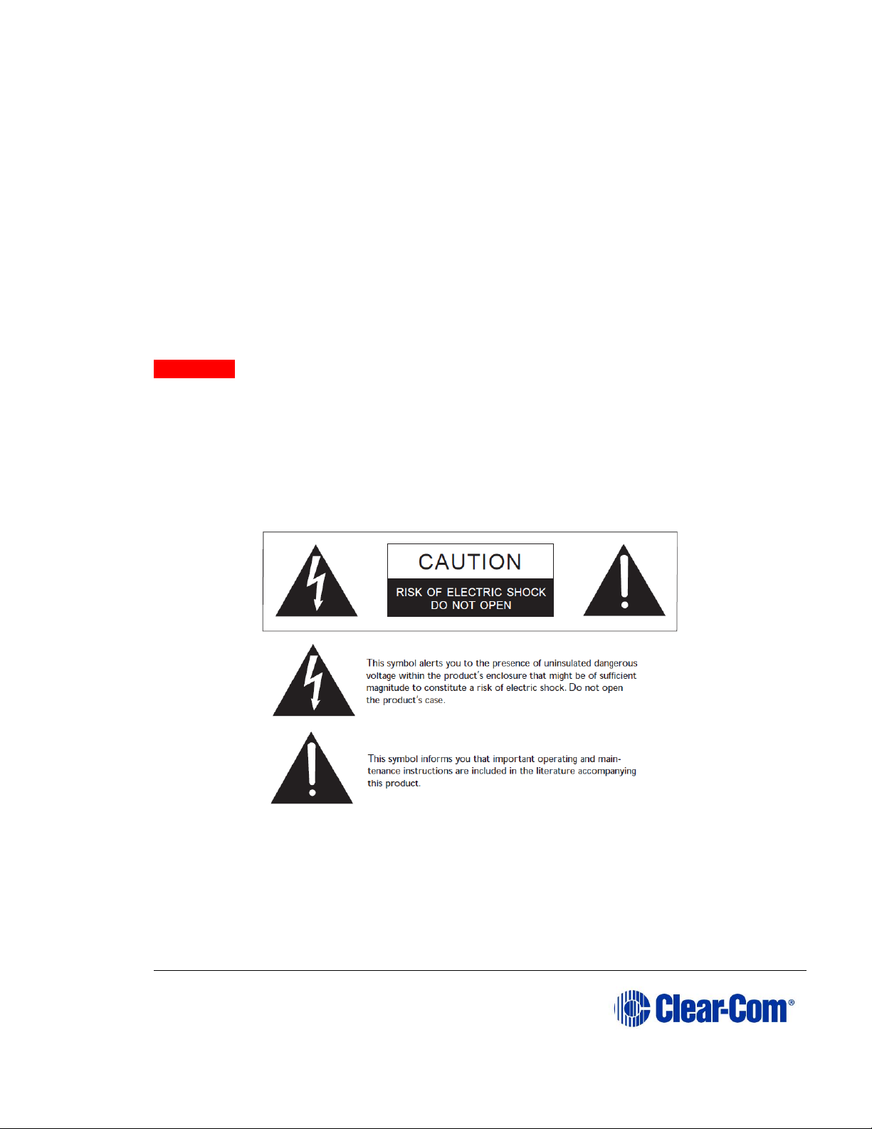
1.1 Safety symbols
Familiarize yourself with the safety symbols in Figure 1: Safety symbols. These
symbols are displayed on the apparatus and warn you of the potential danger of
electric shock if the system is used improperly.
Figure 1-1: Safety symbols
Note: For compliance notices, see Error! Reference source not found. Error! Reference so
urce not found..
Page 9

User Guide| FreeSpeak II® Integra (Matrix version)
Page 9
2 Introduction to FreeSpeak II
®
This chapter provides an overview of the FreeSpeak II digital wireless beltpack
system.
With a FreeSpeak II (FS II) wireless beltpack you can roam freely around a site or
facility while talking and listening to all, or selected, members of the production
team. With its four communication routes, the beltpack gives you the flexibility to
communicate quickly and seamlessly with individuals or groups, and to change
communication routes as often as needed.
The system operates in the unlicensed 1.90 and 2.4 GHz bands. With its unique
and innovative digital technology, which continually searches for unused radio
frequency (RF) channels, FS II avoids the noise and interference issues associated
with traditional wireless systems using congested UHF and VHF bands.
With FS II you can set up a wireless system specifically tailored to local needs by
locating transceiver antennas and beltpacks in areas where they are needed most.
And because the beltpacks operate in the unlicensed 1.90 and 2.4 GHz frequency
spectrum, there is no interference with existing wireless systems, even those
located in the same area.
You can use FS II stand-alone or connected with partyline, digital matrix intercom
systems or both. This manual covers the use of FS II with a matrix connection.
With FreeSpeak II Integra, wireless beltpack users can communicate with any
Eclipse HX panel users on a one-to-one or group basis.
Note: This manual covers the use of FS II with a matrix only (FS II Integra). For more
information on running an FS II system with a Base station, please see FreeSpeak
II User Guide, Base Station Version.
To use FreeSpeak with a matrix, the matrix must be equipped with E-Que cards in
antenna or splitter mode. The system must be configured via the Eclipse HX
Configuration software. See 3.1 Adding an E-Que card to the matrix below.
For more detail, please refer to the Eclipse HX Configuration Software User
Guide, section 5.34 E-Que antenna/E-Que FS II antenna.
Note: You cannot configure FreeSpeak and FreeSpeak II on the same Eclipse matrix. If
you attempt to do so, the Eclipse HX Configuration Software displays a warning.
2.1 An FS II communication system
An FS II system consists of three main elements:
• The wireless beltpacks.
• An Eclipse HX matrix (Omega, Median or Delta) with an E-Que card.
Page 10
User Guide| FreeSpeak II® Integra (Matrix version)
Page 10
• The transceiver network that provide custom coverage zones in which
beltpacks can operate. Beltpacks can roam freely between coverage
zones.
FS II also includes a drop-in battery charger for the beltpack Li-Ion batteries. You
can conveniently charge the battery by placing the whole beltpack into the
charger, or by placing individual batteries into the charger.
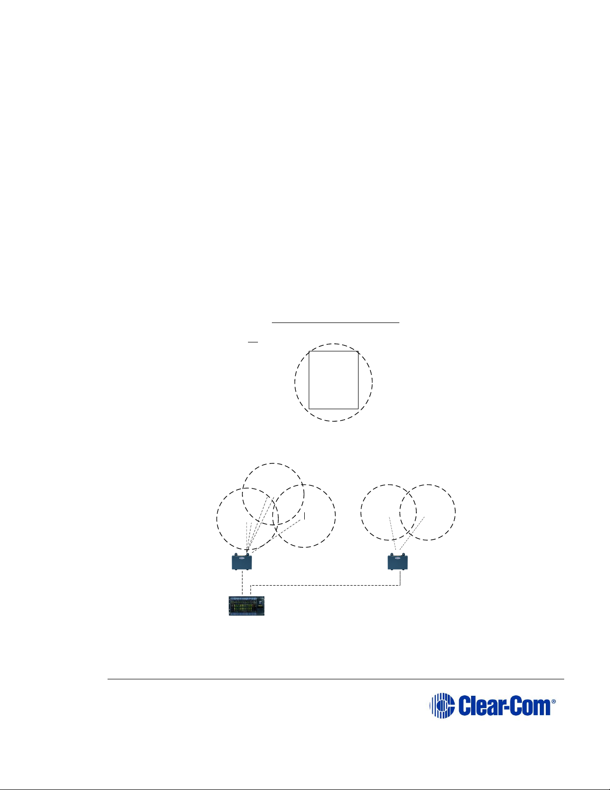
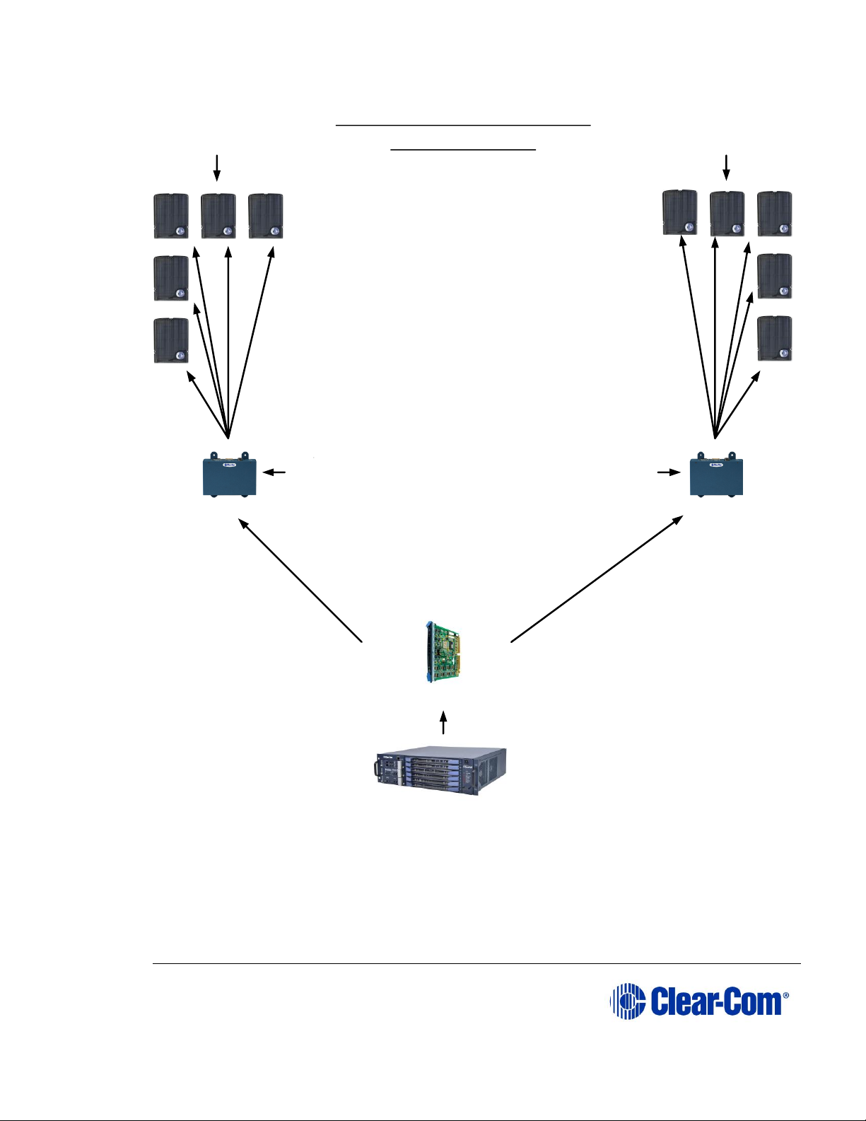
FS II operates using a cellular network of antennas located around a working
environment. The antennas connect to the matrix using CAT5/5e/6 cable via an EQue card installed on the matrix. Each antenna provides an area or cell in which
three to five full-duplex beltpacks can operate. Figure 2-1 shows an example
configuration.
Beltpacks can roam among and between cells without disconnecting because each
beltpack continually signals an antenna as to the strongest available signal. When
the signal from an antenna starts to diminish due to the distance from a beltpack,
the beltpack automatically “hands off” its signal to the nearest antenna, ensuring
smooth transfer.
Figure 2-1 Configurations for a studio and large-scale broadcast facility
XXX
O
O
O
O
O
O
O
O
XX
X
XX
X
X
O
O
O
O
O
O
O
O
O
O
O
O
O
O
O
Single studio (e.g. quiz
show)
Large scale permanent broadcast (e.g. soap opera), one studio
complex
X
Typical FreeSpeak Configurations
FreeSpeak
beltpack user
Active
antenna
KEY
Antenna
splitter
HX Matrix
Page 11

User Guide| FreeSpeak II® Integra (Matrix version)
Page 11
2.1.1 FreeSpeak II system capacity
Using an antenna splitter allows up to five antennas to be connected to each
antenna port. Each E-Que card can connect to two splitters and so support up to
10 antennas. Each antenna supports up to five beltpacks. This means that up to
50 beltpacks can be present, giving a great deal of flexibility in placing beltpacks
where they are needed most, and providing wireless reliability. 2-1 illustrates how
an FS II system can be set up to operate in a single studio or in a large-scale
permanent broadcast facility.
If an antenna card is selected in the configuration software, this supports 8
antennas.
Each matrix can support up to four E-Que cards, allowing for further expansion
and coverage.
Note: Each antenna is designed to handle five beltpacks in the 1.9 GHz range and four
in the 2.4 GHz range, simultaneously and in good conditions. However, if
interference or propagation problems occur in an area, to ensure proper operation
and reliability, it may be more practical to install one less beltpack for each
antenna.
For zones which are likely to need coverage for up to five or more beltpacks
simultaneously you must install a second antenna. Similarly, for good coverage
for nine or more beltpacks simultaneously, a third antenna may be required.
Radio Frequency
(RF) Band
Minimum number. of
Antennas in one RF cell
Maximum number of
beltpacks supported in
one RF cell
1.9 GHz 1 4 - 5 2
8 - 10
3
12 - 15
4
16 - 20
2.4 GHz 1 3 - 4 2
4 - 6 3
7 - 9 4
10 - 12
Figure 2-2 Antenna/beltpack capacity
Page 12
User Guide| FreeSpeak II® Integra (Matrix version)
Page 12
2.1.2 National Radio Carrier Frequencies
The carrier frequencies allocated for a radio space vary according to location. This
affects the amount of belt packs that can be supported in one RF area.
Location
Number of carrier
frequencies
Maximum belt packs
in one RF cell
United States
5
25 belt packs
European Union and
elsewhere
10
50 beltpacks
Figure 2-3 National Radio Carrier Frequencies
Note: If necessary, using two RF bands (1.9 GHz and 2.4 GHz) will increase the amount
of beltpacks that can be used in one area or cell.
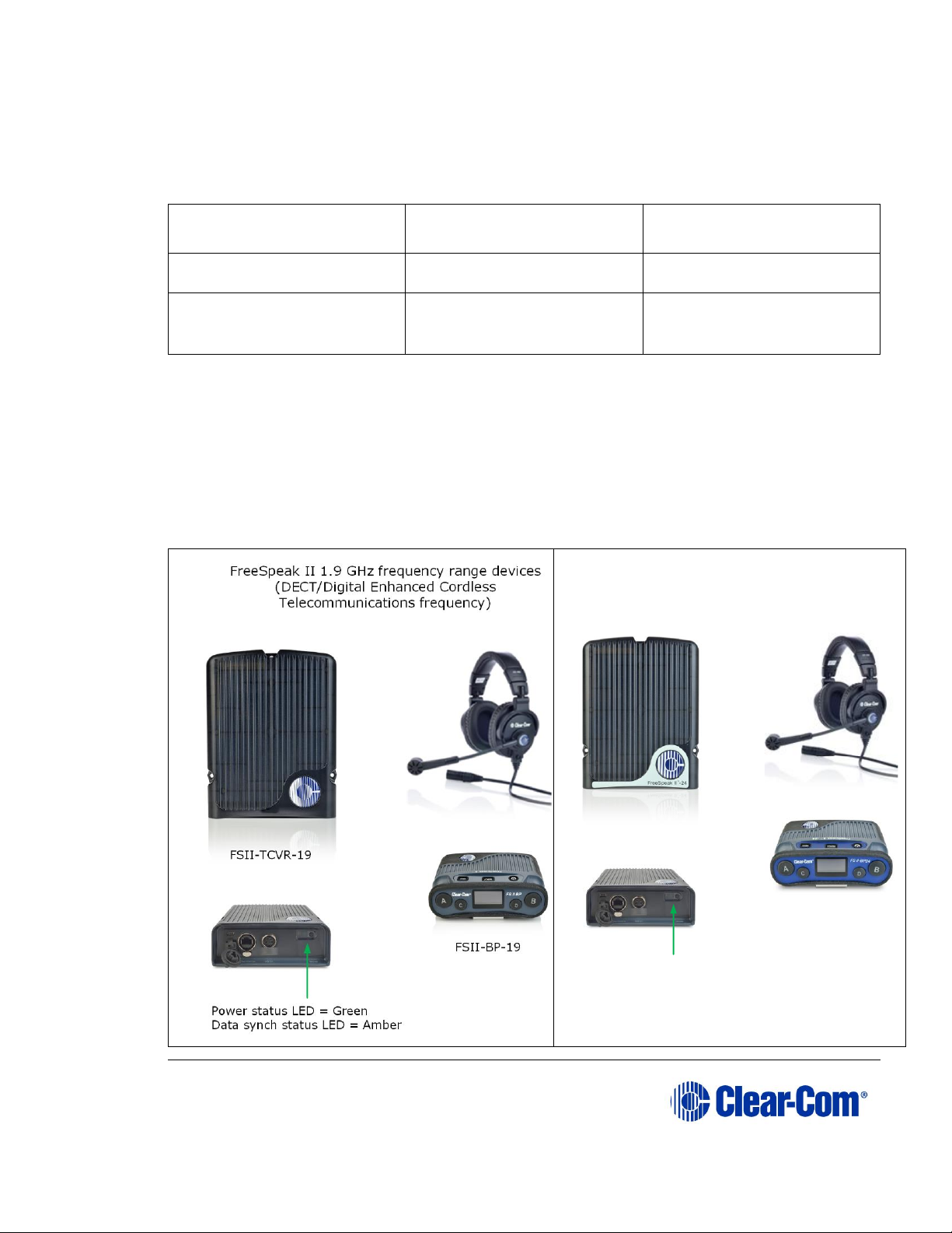
2.1.3 FSII 1.9 GHz/FSII 2.4 GHz
FreeSpeak II 2.4 GHz frequency range devices
(ISM, Industrial, Scientific and Medical frequency)
Power status LED = Blue
Data synch status LED = Amber
FSII-TCVR-24
FSII-BP-24
Page 13

User Guide| FreeSpeak II® Integra (Matrix version)
Page 13
3 Installing a system
This chapter explains how to install a FreeSpeak II system, including cable
connections, registering beltpacks and performing a site survey to optimize
system performance. It contains the following sections:
• Adding the E-Que card for an FS II antenna or splitter to the matrix
• Placing the antennas and splitters
• Connecting to transceiver/antennas
• Determining coverage areas
• Doing a site survey to determine coverage areas
• Registering beltpacks
A FreeSpeak II system can be used with an Omega, Median or Delta matrix.
3.1 Adding the E-Que card for an FS II antenna or
splitter to the matrix
The E-Que card is designed to allow Eclipse HX matrices to connect to FreeSpeak
and FreeSpeak II wireless antennas/beltpacks or connect together using E1 or T1
protocol. You will need an E-Que card and a rear port. You will need to make sure
the E-Que card is physically connected to the matrix and configured for
communication in the Eclipse software. See 3.1.1 and 3.1.2. below.
3.1.1 Installing and removing an E-Que card.
To install an E-Que card:
1) Carefully place the card in the appropriate slot. Make sure the card is
aligned with the top and bottom precision guides.
2) Push the card toward the backplane connectors.
3) When the card has almost reached the backplane connectors, open the
two ejector tabs, allowing them to clear the edges of the matrix. Gently
insert the card further until it touches the backplane connector guides.
4) Gently close both ejector tabs at the same time, to propel the card into
the backplane connectors.
To remove an E-Que card from the matrix:
Page 14

User Guide| FreeSpeak II® Integra (Matrix version)
Page 14
1) Hold the card in place in the matrix.
2) The two card ejector tabs are located at the top and bottom of the card.
To remove a card, open the two ejector tabs at the same time until the
card unseats from its backplane connectors.
3) Pull the card out of the matrix.
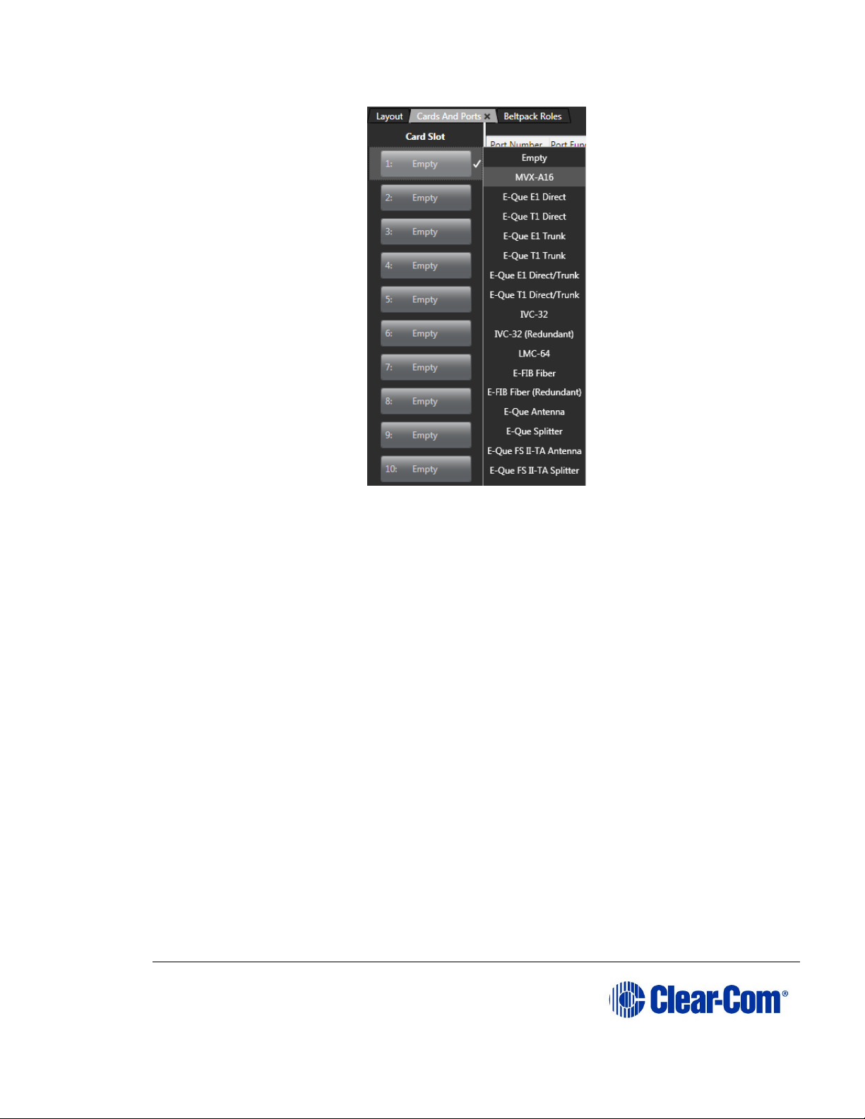
3.1.2 Adding an E-Que card to the software
To add and E-Que card to the software:
1) In the EHX configuration software go to:
2) Hardware > Cards and Ports, navigate to an available slot number
(marked Empty). Do either of the following:
3) Double click the slot.
4) Right click the slot and select Set Card Type.
5) A drop-down menu is displayed, listing the available card types. Select an
FS II antenna or splitter from the drop-down menu.
You cannot have both E-Que Antenna/Splitter and E-Que FS II
Antenna/Splitters configured on the same matrix.
Page 15
User Guide| FreeSpeak II® Integra (Matrix version)
Page 15
Figure 3-1 E-Que Card Selection
3.1.2.1 Selecting an FS II-TA antenna card type
Selecting an FS II-TA antenna card type automatically configures an E-Que card
with eight antenna ports (1 to 8 on the rear card). Each of those antenna ports
provides five user ports and one control port.
3.1.2.2 Selecting an FS II-TA splitter card type
Selecting an FS II-TA splitter card type automatically adds an E-Que card with two
splitter ports (1 and 5 on the rear card) configured. Each splitter can support up
to five antennas and each antenna provides five beltpack ports.
Note: At this stage you might choose to register all of the beltpacks with the matrix, or
at least register one or two for system setup and testing. See Eclipse HX Software
Configuration User Guide, 5.59 FreeSpeak II Beltpacks.
3.2 Placing the antennas and splitters
The next step is to begin placing antennas and splitters to provide the necessary
coverage areas for all of the beltpacks. The first placements of antennas and
splitters will be experimental and temporary. After placing the antennas, walk
through the coverage areas to check for gaps and then re-locate the antennas
accordingly.
Page 16

User Guide| FreeSpeak II® Integra (Matrix version)
Page 16
More information on checking coverage areas is given later in this chapter, in
sections:
• 3.4 Determining coverage areas
• 3.5 Doing a site survey to determine coverage areas
Consider the following:
• What areas will have more than five active beltpack users in them at any
time? Co-locate a second antenna there.
• Is there a central place to locate an antenna so that it will provide
omnidirectional (all directions / circular) coverage?
• Are there balcony areas, corridors, or other rooms or areas that will
require coverage with antennas?
For systems with up to eight transceiver/antennas, the cable runs will go directly
from the transceiver ports on the rear of the E-Que card. If you need more
transceiver/antennas you will need to decide where the splitters that feed these
will be located.
The E-Que card supports two splitters. Each splitter supports up to 5
antenna/transceivers which in turn support up to 5 beltpacks.
For antenna coverage options see 3.4 Determining coverage areas in this
chapter.
3.2.1 Wiring the antennas and splitters
To wire antennas and splitters:
1) Make sure that the local power supplies are plugged into the antennas and
splitters.
2) Run 4-pair shielded Ethernet cable from the matrix (the E-Que card) to
the antenna or splitter, and determine that the antenna or splitter is
showing both power (green) and signal (amber) LEDs. If the amber data
LED flashes, a data link is established, and if the LED is solid, DECT
synchronization is established and the system is ready to use.
The E-Que card will not provide power to the antennas or splitters.
During the initial system setup, before walking through the system with a
beltpack to check for gaps in coverage, it is wise to avoid “permanently” installing
the transceiver/antennas. Hold them in place in some temporary way until their
optimal position is determined.
Note: 4-pair shielded Ethernet cable (CAT-5/5e/6) with RJ-45 connectors on each end is
specified for connection between the matrix and the transceiver/antennas. Use of
Page 17

User Guide| FreeSpeak II® Integra (Matrix version)
Page 17
other cable can result in markedly shorter distances of cable runs and other
possibly other performance problems.
3.3 Connecting to transceiver/antennas
3.3.1 Connecting one transceiver/antenna directly to a
transceiver port
A transceiver/antenna connects to the transceiver port on the E-Que card using a
standard 4-pair CAT-5 data cable with RJ-45 connectors. It may be located up to
1,000 metres from the matrix if 24AWG cable is used or for 500 metres if 26AWG
cable is used creating a coverage area for five FS-BP wireless beltpacks in that
location.
Note: It is recommended that shielded CAT-5 cable or better is used.
To know that a transceiver/antenna is active, observe the green power LED and
the yellow signal LED on the face of the unit where the RJ-45 connector is
connected. Both must be lit. Also, wireless beltpacks in the vicinity of the active
transceiver/antenna will be connected to the system and their displays will show
labels and other information.
For the best, most reliable coverage, it is advisable to use a minimum of two
transceiver/antennas in any installation, positioned in different locations in the
coverage area. When more antennas are required to support a larger coverage
area or more wireless beltpacks, an antenna splitter will need to be introduced.
In some situations, particularly in outdoor venues, interference from non-DECT
sources can severely reduce the range of the system. In these cases we
recommend a site survey as described in Chapter 8, “Installing a System”.
3.3.2 Connecting transceiver/antennas with a splitter
(PD2203)
A splitter (PD2203) will connect up to five transceiver/antennas to one of the
transceiver ports on the E-Que card, creating up to five coverage zones that can
be overlapped to make large areas where beltpacks can have continuous
coverage. The use of the splitter also extends the distance that the transceiver
antennas can be located from the matrix to 2,000 metres (6,400 feet) if 24AWG
cable is used or 1.000 metres (3,200 feet) if 26AWG cable is used (assuming the
same cable type is used to connect the antenna to the splitter and the splitter to
the matrix).
Note: It is recommended that shielded CAT-5 cable or better is used.
For example, a splitter can be used to connect to a matrix that is located in a
production truck outside an arena or stadium, with a single CAT-5 cable going to
the splitter which is then located just inside the stadium. From that splitter, up to
Page 18

User Guide| FreeSpeak II® Integra (Matrix version)
Page 18
five transceiver/antennas are distributed throughout the stadium to create wide
coverage – each with a run of CAT-5 cable back to the splitter. A similar
arrangement may be used in a large theatre or performing arts facility.
The connection between a transceiver port on the E-Que card and a PD2203
splitter is accomplished with standard 4-pair CAT-5 data cable with RJ-45
connectors. It is connected to the port labeled MATRIX on the splitter. The splitter
must be locally powered via its DC IN connector, using the in-line external
universal power supply.
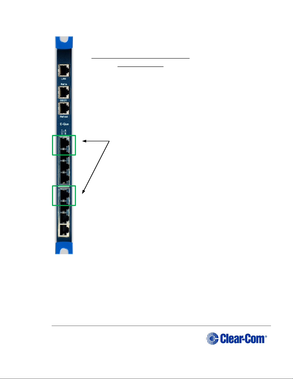
The RJ-45 ports on the splitter labeled “1” through “5” are the connections to the
FS-TA transceiver/antennas.
Ports 1 and 5 on the E-Que card are connections to the PD2203 splitter.
Page 19
User Guide| FreeSpeak II® Integra (Matrix version)
Page 19
Figure 3-2 E-Que card rear connectors, splitter mode
Note: You will need to set the card type to “Splitter mode” in Cards and Ports in the
EHX software interface before connecting the devices. See section 3.1.2. for more
detail.
Ports 1 and 5 (only) will connect to
a PD2203 splitter when the card is
set to Splitter modein Cards
and Ports in the EHX software.
E-Que card rear connectors,
splitter mode
Note: No splitter daisy chains
Page 20
User Guide| FreeSpeak II® Integra (Matrix version)
Page 20
Figure 3-3 Recommended cabling lengths and powering, FreeSpeak™ Integra
3.3.3 Powering an antenna or antenna splitter
Provision of 24 VDC power to an FS II antenna is done as follows:
Matrix
Connection from splitter to antenna:
24 AWG Cat 5/5e/6 max. cable length = 1000m (3281ft)
26 AWG Cat 5/5e/6 max. cable length = 500m (1640ft)
Note: if antennas are NOT locally powered max. cable
length = 250m (820ft).
It is recommended that antennas are powered locally.
Connection from E-Que card to splitter:
24 AWG Cat 5/5e/6 max. cable length = 1000m (3281ft)
26 AWG Cat 5/5e/6 max. cable length = 500m (1640ft)
Note: The splitter MUST be locally powered.
Maximum Cable Lengths and Powering,
FreeSpeak IIIntegra
E-Que card
PSUPSU
PSUPSU
Page 21
User Guide| FreeSpeak II® Integra (Matrix version)
Page 21
• Connect the antenna to a 453G023 power supply unit through the 4-pin DIN
connector at the antenna.
3.4 Determining coverage areas
After the transceiver/antennas and splitters have been initially set up proceed to
test the coverage areas and re-locate antennas and splitters, if necessary, for
optimal coverage.
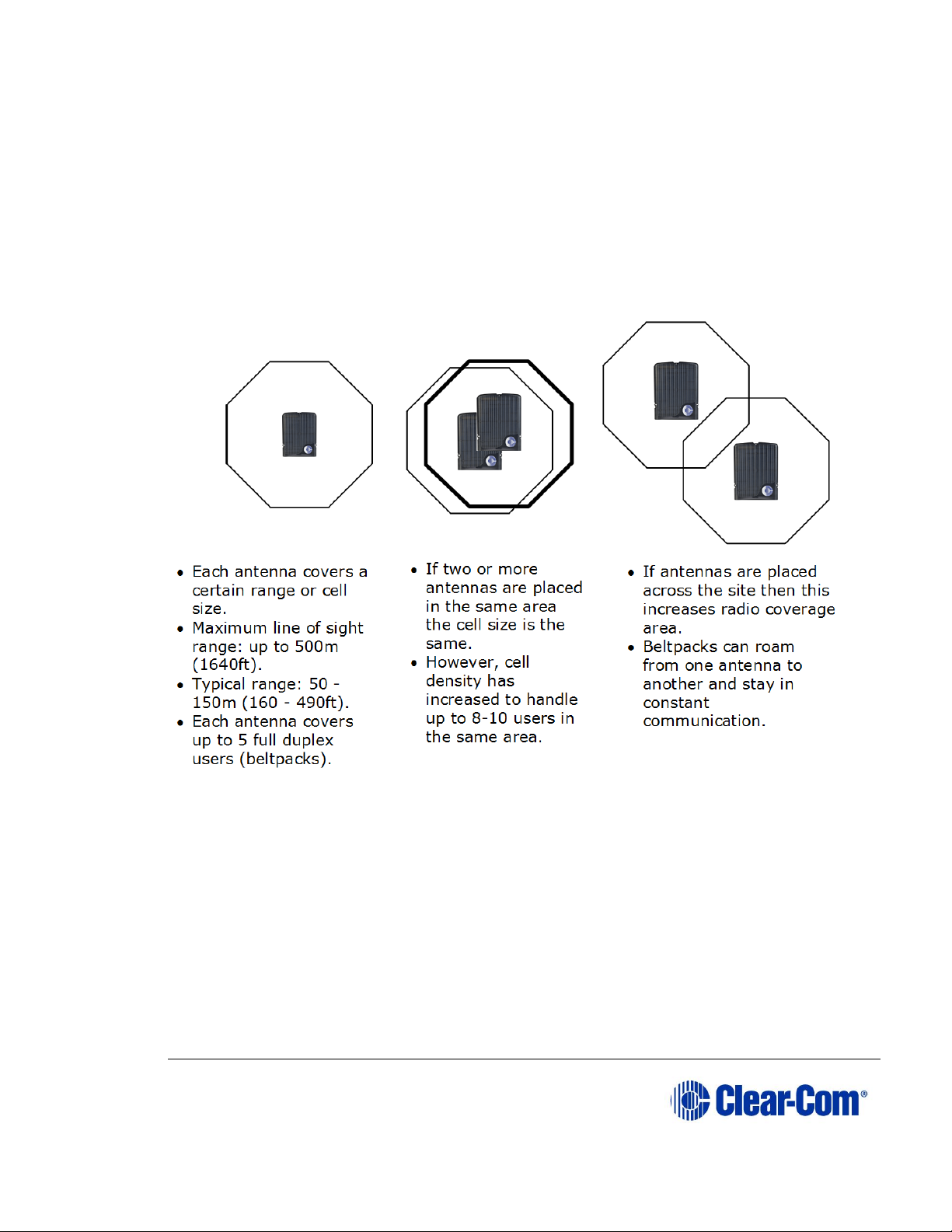
The following figure illustrates some FreeSpeak II coverage scenarios.
Figure 3-4 Coverage areas for FS II TAs
Note: Cells can be completely overlapped for density (by co-locating multiple antennas).
Cells can be overlapped at boundaries (increases radio coverage).
For most working systems Clear-Com uses a ratio of 3-4 (1.9GHz) or 2-3
(2.4GHz) users per antenna. This is due to system losses.
Note: Under ideal conditions, the maximum range between an FS II beltpack and a
transceiver/antenna is 500 metres. Typical distances are between approximately
50 metres (about 160 feet) and 150 metres (about 490 feet), depending on the
particular environment.
To determine coverage areas:
Page 22
User Guide| FreeSpeak II® Integra (Matrix version)
Page 22
1) When the matrix, splitter(s), and transceiver/antennas have been placed
and wired, turn on an FS II beltpack (assuming that it has been registered
with the system) and walk the coverage area.
Alternatively, use the Site Survey mode on the beltpack (see 3.5 Doing a site
survey to determine coverage areas below). It is often best to begin with one
antenna in place, and then place additional units to enhance coverage.
2) Walk through all of the areas where beltpack users will typically be
moving, and note any areas of weak signal, dropout, or disconnection
from the system. Pay special attention to the overlap areas between
antenna coverage zones, making sure sufficient signal strength is there
from each of the transceiver/antennas to make a clean handoff between
them for the beltpack.
3.5 Doing a site survey to determine coverage areas
You might want to test coverage areas more extensively before setting up a
complete system. Testing a system in the setting in which it will be located helps
to meet operational needs. Factors in the local setting may affect the areas a
system can cover, so it is important to plan a site setup accordingly.
Doing a complete site survey, as described below, helps to set up an optimal
system. You can do a site survey using a beltpack that is connected to the system
or one that is not connected to the system.
3.5.1 Doing a site survey with a beltpack
1) Link one beltpack to the matrix.
2) Place one connected antenna in the center of the coverage area.
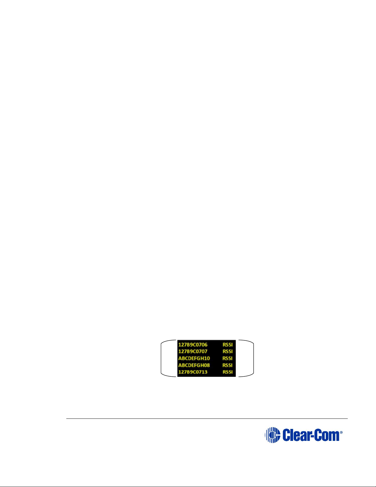
3) Put the beltpack into Site Survey mode using the beltpack menu. See 4
Operating the wireless beltpack. The following figures show the
information that the Site Survey mode displays for connected and
unconnected beltpacks.
Figure 3-4 An unconnected beltpack site survey screen
Received signal
strength indication
(RSSI)
8-digit system name
and 2-digit RPN
Page 23

User Guide| FreeSpeak II® Integra (Matrix version)
Page 23
Figure 3-5 A connected beltpack site survey screen
Parameter
Meaning
Received Signal Strength Indication
(RSSI)
A measure of the signal strength in a
wireless environment. The higher the
value, the stronger the signal.
Frame Error Rate (FER)
A measure of the signal connection
quality. The lower the FER, the better
the signal connection.
Link Quality (LQ)
A combined quality metric ranging
from 1 (poor) to 5 (high).
Table 3-1 Key to site survey terms
4) Walk around the antenna with the beltpack, monitoring the beltpack signal
strength and quality metrics.
The signal strength is shown in the Received Signal Strength Indication (RSSI)
field.
• The signal strength number will fluctuate, ranging between 0 - 59 as you
walk through the coverage area, and may even fluctuate as you stand
still. As a rule-of-thumb the best system performance will be obtained
when the signal strength remains at 30 or above. If the signal strength
falls below 30 the beltpack may start losing audio. This is the limit of the
coverage zone.
• A high Received Signal strength indication and a high Error rate may
indicate that there is another RF system causing interference.
A beltpack can transmit to an antenna at a range of approximately 500m in good
conditions.
5) Draw a map of the coverage zone for the antenna. The coverage zone is
the area where the signal strength, as a rule-of-thumb, is 30 or above and
the Line Quality is 3-5.
2-digit RPN
Frame error rate Link quality
Page 24

User Guide| FreeSpeak II® Integra (Matrix version)
Page 24
6) Repeat this process for as many antennas as necessary to cover the
required area. Overlap coverage zones so that there is no area where the
signal strength is below 30, and no area where the error rate is above a
few percent.
7) The antenna placement will need to be adjusted to get the best coverage.
Figure 3-6 Mapping overlapping coverage zones
In some environments you might observe that despite having a high signal
strength, the beltpack consistently reports a high error rate.
This could be due to two things:
• In-band interference from an RF source broadcasting in the DECT area of
the spectrum. This can be verified using a DECT band monitor or by using
a Spectrum Analyzer.
• Long Delay Spread Multipath, where the signal is bounced off a number of
reflective surfaces, such as metal ceilings, gantries, walkways or other
large structures. This problem is greatest where the reflective surface is
large and exists at a range of distances from the antenna. To reduce the
problem, consider siting the antenna where it cannot “see” the reflective
surface or installing a reflector close to the antenna between it and the
reflective surface.
3.5.2 Testing antenna handoff
After testing the coverage areas for individual antennas, test the handoff between
the antennas. When you walk through a coverage area with the beltpack, the
beltpack searches to find the antenna with the best signal strength, and switches
transmission to that antenna. Therefore the beltpack continually hands off
transmission among antennas as you move through the coverage area. You can
determine which antenna the beltpack is connected to using the EHX
configuration.
To test antenna handoff, connect any additional antennas in the installation and
walk through the coverage areas to ensure that the coverage is continuous and
complete, without audio breakups. Reposition antennas if necessary.
Zone A
1 user
Zone C
4 users
Zone B
5 users
Page 25

User Guide| FreeSpeak II® Integra (Matrix version)
Page 25
3.5.3 Assigning beltpacks to coverage areas
Antennas that operate in the 1.9 GHz band will handle up to 5 antennas at any
one time. Antennas that operate in the 2.4 GHz band will handle up to 4
antennas.
Although they can achieve this in good conditions, this may not always be
possible for a number of reasons. First, interference or propagation problems may
mean that not all antenna slots are available all the time. Second, a beltpack
constantly searches for the best antenna signal, and may frequently switch
antennas. To make this transmission seamless, a beltpack maintains the
connection to its current antenna until it is confident that the new antenna is
functioning well. Therefore, for a short period of time during this transition, a
single beltpack can occupy slots on more than one antenna.
This means that for zones likely to need coverage for five or more beltpacks
simultaneously it is recommended that a second antenna is installed. Similarly,
for good coverage for nine or more beltpacks simultaneously, a third antenna may
be required (remember that the 2.4 band will support one less beltpack per
antenna).
3.5.4 Conditions affecting coverage areas
The environment in which a system is located affects the coverage area for any
particular beltpack/antenna combination. The presence of walls, floors, ceilings,
trees, shrubbery, people, and numerous other items may affect the coverage
zone. Metallic objects, safety doors, lighting equipment, and bodies of water may
possibly block transmission. These factors must be taken into consideration when
planning the installation.
3.5.5 Surveying a site in standalone (rigging) mode
You might need to scope a site (check the range and performance of an antenna)
without connecting to a matrix. To do this, a beltpack and antenna can be put into
standalone or rigging mode.
To put a beltpack and antenna into standalone mode:
Make sure you have to hand:
• A beltpack
• A transceiver/antenna
• A power connector for the antenna.
• Access to a power socket.
8) Connect the power to the transceiver/antenna and at the same time
press the black mode button on the base of the antenna.
Page 26

User Guide| FreeSpeak II® Integra (Matrix version)
Page 26
This puts the antenna in standalone mode, and opens it for pairing to a
beltpack.
9) The amber LED flashes continuously to show that the antenna is open for
pairing with a beltpack in standalone mode.
10) From the beltpack, press the menu key (3 second press) and navigate to
System Connect using the right hand rotary controller on the beltpack.
11) Press button D to see local systems available for connection.
Note: In menu mode the D key on the beltpack operates as SELECT and
the C key exits the menu level and cancels the selection.
12) Scroll through available systems using the right hand rotary controller.
13) When you have found the antenna to pair to (it will be showing a ‘P’ to
indicate that it is ready to be paired to the beltpack) press button D to
select the antenna and connect the beltpack to it.
14) When the beltpack is successfully connected to the antenna, navigate to
Site Survey in the beltpack menu and monitor the range and
performance of the antenna. For more information on Site Survey
functionality see 3.5.1 Doing a site survey with a beltpack.
Page 27

User Guide| FreeSpeak II® Integra (Matrix version)
Page 27
Figure 3-7 Using an antenna and beltpack in standalone mode
3.6 Registering beltpacks
Before you can use a beltpack, you must first register it with the FreeSpeak II
system. The beltpacks can be registered to an Eclipse matrix (Omega, Median or
Delta) using Eclipse HX software (EHX).
You can register the beltpacks using a USB cable or over the air (OTA).
To register FreeSpeak beltpacks with the system see the Eclipse HX Software
Configuration User Guide, 5.59 FreeSpeak II Beltpacks.
Page 28

User Guide| FreeSpeak II® Integra (Matrix version)
Page 28
4 Operating the wireless beltpack
This chapter explains how to operate the FS II beltpack. It contains the following
sections:
• Overview of the wireless beltpack
• Beltpack user controls
• Using the beltpack
4.1 Overview of the wireless beltpack
Figure 4-1 FreeSpeak II beltpack
An FS II wireless beltpack gives you simultaneous access to up to five channels of
talk/listen communication, with the ability to switch among them as desired. Any
or all of these routes may be kept open during use. You can adjust Incoming
volume levels (“listen levels”) using the two rotary level controls, so that one
conversation can be monitored in the background while a primary conversation is
held.
The panel display contains the role (label) of the beltpack user, identifies up to
four talk/listen labels currently selected, and gives other information such as
signal strength and battery level. You can choose between two display modes:
• Intercom display mode – displays key labels, role name, signal strengths,
battery level and volume levels.
Page 29

User Guide| FreeSpeak II® Integra (Matrix version)
Page 29
Figure 4-2 Intercom display mode
• Partyline display mode – displays role name, signal strength, battery level
and volume levels for channel A and channel B.
Figure 4-3 Partyline display mode
A B
D
C
G
H
I
E F
H
I
G
E
F
Page 30

User Guide| FreeSpeak II® Integra (Matrix version)
Page 30
Key to display layout
Feature
Description
A
Label for key A assignment.
B
Label for key B assignment.
C
Label for Key C Assignment or CALL key for Key A if not assigned.
D
Label for Key D Assignment or CALL key for Key B if not assigned.
E
Volume level for Key A assignment.
F
Volume level for Key B assignment.
G
Signal strength.
H
Role name for the role assigned to the Beltpack.
I
Battery life remaining (in hours for Li-Ion, in % for AA battery).
Table 4-1 Key to display layout
A 4-pin male headset connector is provided for connection with a standard ClearCom headset or similar device. The FS II beltpack will operate for approximately
18 hours using a rechargeable Li-Ion battery. Real operational times depend on
usage and quality of batteries used. You can also use AA batteries, but you must
not attempt to recharge them.
On the bottom of the beltpack, there is an LED torch with a latching key that
provides a quick and convenient source of illumination when working in poorly lit
areas.
Page 31

User Guide| FreeSpeak II® Integra (Matrix version)
Page 31
4.2 Beltpack user controls
4.2.1 Top controls
Figure 4-4 View of top of beltpack
Key to beltpack top controls
Feature
Description
A
Talk key A and B. Press to talk or listen on channel A and channel
B.
B
Talk key C. Press to talk or listen on channel C.
In menu mode, press to cancel menu.
C
Talk key D. Press to talk or listen on channel D.
In menu mode, press to select menu.
D
Display. When the beltpack is not in menu mode, information about
each of the four channels supported by the beltpack is displayed on
A
B
C
D
Page 32

User Guide| FreeSpeak II® Integra (Matrix version)
Page 32
Key to beltpack top controls
Feature
Description
screen. Exactly what is present on the screen depends on the display
mode (intercom or partyline).
Table 4-2 Key to beltpack top controls
4.2.2 Beltpack display
The following table lists the beltpack display icons and indicators.
Beltpack display icons and indicators
Name
Icon
Description
Key label
A descriptive name for the channel. The
maximum length is 10 characters.
Role name
A descriptive name for the beltpack role.
Channel
listen
volume level
The volume of the channel audio.
Signal
strength
Bars that indicate the strength of the signal from
the Main Station.
Battery
level
Indicates the battery time remaining.
Table 4-3 Beltpack display icons and indicators
4.2.3 Beltpack headset tones/alerts
Note: To change call signal, low battery or out-of-range alerts go to Menu (press and
hold) -> Settings -> Alarm options on your beltpack. Choose from Vibrate &
audio/Vibrate only/Audio only/Off.
Beltpack headset tones/alerts
Event
Tone
Call signal
Mid to high beep, as long as call is
active
Mid on 200ms, mid off 0ms, high on
200ms, high off 400ms. Repeat if key
held.
Page 33

User Guide| FreeSpeak II® Integra (Matrix version)
Page 33
Low battery
High beep, long then short.
High, on 400ms, off 100ms, on 100ms.
Repeats intermittently.
Out-of-range
High beep, long then short (as above).
Repeats as long as beltpack is out of
range.
Menu button
Mid beep.
Mid, on 100ms, off 100ms.
Triggers on entering menu mode.
Power button
Mid beep.
Mid, on 100ms, off 100ms, repeated
while power button pressed.
Listen again
Low beep.
Low, on 100ms, off 100ms.
Figure 4-5 Beltpack headset tones/alerts
Page 34

User Guide| FreeSpeak II® Integra (Matrix version)
Page 34
4.2.4 Front controls
Figure 4-6 Beltpack front controls
Key to beltpack front controls
Feature
Description
A
Right rotary level control. Turn clockwise or counter-clockwise to
adjust volume.
In menu mode, turn clockwise or counter-clockwise to navigate the
menus.
B
Power button. Press to power up or power down the beltpack.
C
Reply key. Reply key can be configured as an extra fifth channel
using the Configuration Editor or EHX software.
D
Menu key. Press firmly for about two seconds to enter menu mode
To exit menu mode, press the menu key again. If you tap the Menu
A
BCD
E
Page 35

User Guide| FreeSpeak II® Integra (Matrix version)
Page 35
Key to beltpack front controls
Feature
Description
key, the Listen Again feature is activated. See 5.9 Setting the
listen again option.
E
Left rotary level control. Turn clockwise or counter-clockwise to
adjust volume.
In menu mode, turn clockwise or counter-clockwise to navigate the
menus.
Table 4-4 Key to beltpack front controls
4.2.5 Beltpack bottom connectors
Figure 4-7 Beltpack bottom connectors
Key to beltpack bottom connectors
Feature
Description
A
LED torch
Page 36

User Guide| FreeSpeak II® Integra (Matrix version)
Page 36
Key to beltpack bottom connectors
Feature
Description
B
LED torch control
C
Headset socket (4-pin XLR–M)
Pin
Function
1
Mic ground
2
Mic +
3
Earphone ground
4
Earphone
Table 4-5: Headset socket pin out
Headset socket (7-pin XLR–M)
Pin
Function
1
Mic ground
2
Mic +
3
Ground
4
Left Headphone Output
5
Right Headphone Output
6
PTT1
7
PTT2/Headset detect
Table 4-6: Headset socket pin out
D
3.5 mm stereo jack.
E
Micro USB connector.
Table 4-7 Key to beltpack bottom connectors
Page 37

User Guide| FreeSpeak II® Integra (Matrix version)
Page 37
4.2.6 Beltpack rear panel
Figure 4-8 Beltpack rear panel
Key to beltpack rear panel
Feature
Description
A
Beltpack clip
B
Beltpack battery compartment
Table 4-8 Key to beltpack rear panel
4.3 Using the beltpack
4.3.1 Registering the beltpack
Before you can use a beltpack, you must first register it with the FreeSpeak II
system. For more information, see the Eclipse HX Software Configuration User
Guide, 5.59 FreeSpeak II Beltpacks.
Page 38

User Guide| FreeSpeak II® Integra (Matrix version)
Page 38
4.3.2 Charging the beltpack
The beltpack batteries are located inside the beltpack battery compartment. The
beltpack can use a Clear-Com rechargeable Li-Ion battery or AA batteries. A
dedicated battery charger can charge up to five batteries simultaneously.
You can also recharge batteries by using the supplied USB charger. Do not use
any other USB charger.
To recharge the beltpack battery:
1) Insert either the beltpack containing the battery, or the battery itself into
one of the recharging bays on the battery charger. A red LED indicates
that the battery is recharging.
If you are recharging the battery while it is still in the beltpack battery
compartment, an illuminated beltpack key (Talk key A) indicates the
charging status. The beltpack charging sequence depends on whether you
insert a powered on unpowered beltpack into the charger. The table below
shows the charging status conditions.
Talk key A
red
Talk key A
green
RF
component
Beltpack
screen
Battery
charging
Battery fully
recharged
Disabled
Displays
current
percentage
charge and
software
version
Note: If a beltpack is powered on when placed in the charger, on
removal the RF component is re-enabled and the beltpack
attempts to reconnect to its previous connection.
Note: If a beltpack is powered off when placed in the charger, on
removal it will power off.
2) Wait until the recharging LED turns from red to green. The battery is now
fully recharged.
Page 39

User Guide| FreeSpeak II® Integra (Matrix version)
Page 39
Figure 4-9 FreeSpeak II battery charger
4.3.3 How to set AA battery type: Nickel-metal hydride (NiMHi)
or Alkaline for wireless beltpacks
FreeSpeak II wireless beltpacks are supplied with Li-ion batteries and battery
charger. However, in some cases you may wish to use AA batteries. You may
need to use standard, AA Alkaline batteries, or, in a high atmospheric pressure
(hyperbaric) environment you can’t use Li-ion batteries and need to use NiMHi
batteries.
When using AA batteries of either kind, it is helpful to set battery type so that
battery capacity can be monitored accurately. NiMHi batteries and alkaline
batteries have different discharge patterns and setting this option will allow for
that.
AA Battery type must be set in the EHX software.
3) Open the EHX configuration software and navigate to
Preferences/Wireless Beltpacks/Battery type.
4) Select required battery type, NiMHi or Alkaline.
Note: the default setting for AA battery type is Alkaline
Page 40

User Guide| FreeSpeak II® Integra (Matrix version)
Page 40
Figure 4-10 Set Battery type
4.3.4 Powering on the beltpack
The recessed power button is used to turn the FS II beltpack on and off. Press and hold the
button for about three seconds to turn the beltpack on. To turn it off, press and hold the button
for about three seconds.
4.3.5 Using the beltpack to communicate
The beltpack has four keys labelled A, B, C, D and Reply. You can program each of these
keys to determine their communication destinations, and the type of communication possible.
For example, a key could be programmed to call a partyline channel, with both talk and listen
enabled. You can program the beltpack keys by using:
• The Eclipse HX software. For more information, see the Eclipse HX
Configuration Software User Guide.
To talk to all the devices connected to the channel:
Page 41

User Guide| FreeSpeak II® Integra (Matrix version)
Page 41
5) Connect a headset, using the 4-pin XLR–M connector on the base / rear of
the beltpack.
6) Press the appropriate key.
While the key is held down audio transmits on that channel. When the key
is released audio no longer transmits. To latch a key on for hands-free
use, quickly tap the key. Another quick tap releases the latch.
7) Speak into the headset microphone.
To adjust the volume of incoming audio for a channel, turn the
appropriate side-mounted rotary control. Turn the rotary control
clockwise to increase the volume, and counter-clockwise to decrease
volume. The current volume level for the channel is shown on screen.
4.3.6 Entering and exiting Menu mode
Use Menu mode to:
• Configure the settings for the beltpack.
• Read beltpack information such as software version
• Perform a site survey to maximize signal strength and coverage.
To enter Menu mode, press and hold the Menu key for three seconds. To exit
Menu mode, press the Menu key again.
For more information about using Menu mode on the beltpack, see 5.1
Introduction to programming on the beltpack.
.
4.3.7 Setting and Adjusting Listen Levels
You can adjust a beltpack’s incoming audio volume in two ways:
• The master volume level for the beltpack can be set by using the beltpack
menu options. See 5.2 Configuring the beltpack volume settings.
• The incoming audio level can be adjusted during talk or listen on the
beltpack using the beltpack’s rotary level controls.
To adjust the listen level during talk or listen from the beltpack:
• During talk and listen, use the rotary level control to increase or decrease
the incoming volume level (“listen level”) for that assignment.
Note: You can also configure the incoming audio volume using the EHX software.
Page 42

User Guide| FreeSpeak II® Integra (Matrix version)
Page 42
4.3.8 Upgrading beltpack firmware
You can upgrade the FreeSpeak II beltpack firmware by:
• Using a USB connection
• Using an Over The Air upgrade.
4.3.8.1 Upgrading by USB connection
1) Connect the beltpack to a USB port on the computer running the EHX
software.
2) Select Tools > Apply Wireless Firmware Via USB.
3) Browse to the location of the upgrade file, and then select Update
Firmware.
The upgrade file is downloaded to the beltpack or antenna.
Note: You can connect more than one beltpack to the computer if you have multiple
USB ports. The units will be upgraded sequentially.
4.3.8.2 Upgrading beltpack firmware by Over The Air Upgrade
1) Right-click on the Frame in the Layout window, and then select Firmware
> Update Firmware. The Update Firmware Wizard appears.
2) Select Next. The following screen appears:
Figure 4-11 The Update Firmware screen
3) Select the Wireless radio button. There are two further options:
• Automatic – select this option to automatically upgrade the beltpack
when it is switched on.
Page 43

User Guide| FreeSpeak II® Integra (Matrix version)
Page 43
• Prompted – select this option to allow the beltpack user to confirm the
upgrade.
4) Select Next, and then browse to the upgrade file (.fww) and select
Open. The upgrade file is loaded to the antenna. The upgrade file is
downloaded to all the connected beltpacks, and the beltpacks
automatically restart.
Note: The antennas store the beltpack upgrade files until they are power
cycled or there is a black reset.
Note: You can track the status of the download in the EHX Event Log,
and for beltpack upgrades the upgrade status is also shown on the
beltpack display.
Page 44

User Guide| FreeSpeak II® Integra (Matrix version)
Page 44
5 Programming on the beltpack
This chapter explains how to program the beltpack using the beltpack's menu
system. It contains the following sections:
• Introduction to programming on the beltpack
• Configuring the beltpack volume settings
• Configuring the beltpack headset
• Configuring the beltpack microphone
• Configuring the beltpack display
• Configuring the beltpack alarm options
• Selecting the beltpack role default set
• Selecting the beltpack administration
• Setting the listen again option
• Accessing beltpack information
• Setting display mode
• Setting system connect
• Enabling over the air (OTA) registration mode from a beltpack
• Performing a site survey
5.1 Introduction to programming on the beltpack
You can access the beltpack menu by pressing and holding the menu key. The
Master Menu screen is displayed. This consists of the following submenus:
• Volume Level Control
• Volume Operation
• Line In Volume Level
• Settings
• Information
• Display Mode
• System Connect
• Site Survey
Note: The menus that appear depend on the menu access level. See 5.8.2 Setting full
menu access.
Page 45

User Guide| FreeSpeak II® Integra (Matrix version)
Page 45
To select a submenu turn either of the two rotary dials clockwise. This will scroll
down the submenu options. If you turn the rotary dials counter-clockwise, you will
scroll upwards.
To select a submenu, press the Menu Select key (D).
To return to the previous screen, press the Menu Cancel key (C). You can also
return to the previous screen by pressing the Menu key.
Each menu screen on the beltpack has the following structure:
• Header - this displays the menu title
• Body - this displays a scrollable list of menu items
• Footer - this displays the current value of the current menu selection
To exit the beltpack menus, press the Menu key.
5.2 Configuring the beltpack volume settings
You can configure the following:
• The volume on each of the four channels
• The beltpack master volume
• The volume of the line-in feed.
Rotary controllers. Scroll through
menu items in menu mode.
Press to enter menu mode
Menu
cancel key
Menu
select key
Beltpack menu controls
Page 46

User Guide| FreeSpeak II® Integra (Matrix version)
Page 46
5.2.1 Configuring the beltpack channel volumes and master
volume
Each of the four beltpack channel volume levels is configurable separately.
Note: You can only change volume levels on keys that have been configured.
To configure a channel volume:
1) To enter the beltpack menu, press and hold the Menu key.
2) Turn either rotary control clockwise to highlight Vol Level Ctrl, and press
the Menu Select key (D). The Volume Level Control screen appears:
3) Use the left-hand rotary control to select the required channel, or select M
for the master volume
4) Use the right-hand rotary control to adjust the volume level. The default is
0dB for channel audio, and -9.6dB for master volume.
Note: The volume level appears in the footer.
5) To confirm the selection, press the Menu Select key (D).
5.2.2 Configuring the volume level of the line input
You can configure the volume of an audio line input:
1) To enter the beltpack menu, press and hold the Menu key.
2) Turn either rotary control clockwise to highlight Line In Vol Lvl, and
press the Menu Select key (D).
3) Use either rotary control to select between -15 dB to 6dB
4) To confirm the selection and exit the menu screen, press the Menu
Select key (D).
5.2.3 Configuring the rotary controls
You can configure the rotary controls on the beltpack to either:
• Control the volume of the audio on keys A and B
Page 47

User Guide| FreeSpeak II® Integra (Matrix version)
Page 47
• Control the master volume of the beltpack audio.
1) To enter the beltpack menu, press and hold the Menu key.
2) Turn either rotary control clockwise to highlight Vol Operation, and press
the Menu Select key (D).
3) Use either rotary control to select between:
• Talk Key
• Master
4) To confirm the selection and exit the menu screen, press the Menu
Select key.
5.3 Configuring the beltpack headset
You can configure the following headset settings:
• Headset autodetect
• Headset sidetone level
• Headset limiter
The menus that appear depend on the menu access level. See 5.8.2 Setting full
menu access.
5.3.1 Setting headset autodetect
Use this setting to allow the beltpack to automatically detect when you plug in a
headset, and route the audio to the headset.
Note: To use this feature, first set Mic Type to Auto. See 5.4.1 Setting the
microphone type.
1) To enter the beltpack menu, press and hold the Menu key.
2) Use the rotary and Menu Select keys to select Settings > Headset
Options > Auto Detect.
3) Use either rotary control to select between:
• On
• Off
4) To confirm the selection and exit the menu screen, press the Menu
Select key (D).
Page 48

User Guide| FreeSpeak II® Integra (Matrix version)
Page 48
5.3.2 Setting the sidetone level
Use this setting to set the level of the sidetone. You can either set the sidetone to
a fixed level, or choose to have the sidetone track the master volume level. To set
sidetone to a fixed level:
1) To enter the beltpack menu, press and hold the Menu key.
2) Use the rotary and Menu Select keys to select Settings > Headset
Options > Sidetone > Sidetone Level.
3) Use either rotary control to select the sidetone level between -70dB and
0dB.
4) To confirm the selection and exit the menu screen, press the Menu
Select key.
5.3.3 Setting the headset limiter
Use this setting to limit the incoming headset audio level to prevent excessive
sound levels.
1) To enter the beltpack menu, press and hold the Menu key.
2) Use the rotary and Menu Select keys to select Settings > Headset
Options > Limiter.
3) Use either rotary key to select the limiter level between -12 and 8dB. The
default is 0dB.
4) To confirm the selection and exit the menu screen, press the Menu
Select key (D).
5.4 Configuring the beltpack microphone
You can configure the following microphone settings:
• Microphone type
• Microphone echo cancellation
The menus that appear depend on the menu access level. See 5.8.2 Setting full
menu access.
Page 49

User Guide| FreeSpeak II® Integra (Matrix version)
Page 49
5.4.1 Setting the microphone type
Use this setting to specify the type of microphone you are using. You can also
allow the beltpack to automatically detect what kind of microphone is present.
1) To enter the beltpack menu, press and hold the Menu key.
2) Use the rotary and Menu Select keys to select Settings > Mic Options
> Mic Type.
3) Use either rotary control to select between:
• Automatic (default)
• Electret
• Dynamic Unbalanced
4) To confirm the selection and exit the menu screen, press the Menu
Select key (D).
Note: If automatic headset detection is ON:
• Dynamic headset is detected if microphone impedance is between 90 –
320 Ohms
• Electret headset is detected if microphone impedance is between 1.3 – 6.5
kOhms.
5.4.2 Setting the microphone echo cancellation
Use this setting to improve the microphone audio quality.
1) To enter the beltpack menu, press and hold the Menu key.
2) Use the rotary and Menu Select keys to select Settings > Mic Options
> Echo Cancellation.
3) Use either rotary control to select between:
• On
• Off (default)
4) To confirm the selection and exit the menu screen, press the Menu
Select key.
Page 50

User Guide| FreeSpeak II® Integra (Matrix version)
Page 50
5.5 Configuring the beltpack display and LEDs
You can configure the following display options:
• Display brightness level
• Display dim timeout
• Display off timeout
5.5.1 Setting the display and LED brightness
Use this setting to control the brightness of the display. The beltpack
automatically dims after a timeout period if no key is used or there is no incoming
call or call alert. You can adjust the timeout period.
When the beltpack is dimmed, the display goes off after a timeout period if no key
is used or there is no incoming call or call alert. You can adjust the timeout
period.
1) To enter the beltpack menu, press and hold the Menu key.
2) Use the rotary and Menu Select keys to select Settings > Display
Options > Brightness Level
3) Use either rotary control to select the dim level between 1 and 5 (default).
4) To confirm the selection and exit the menu screen, press the Menu
Select key.
5.5.2 Setting the display dim timeout
Use this setting to determine when the beltpack display will dim if no key is used
or there is no incoming call or call alert.
1) To enter the beltpack menu, press and hold the Menu key.
2) Use the rotary and Menu Select keys to select Settings > Display
Options > Dim Timeout
3) Use either rotary control to select the dim level between Off and 120
seconds (default).
Note: Setting the dim timeout to Off disables the timeout function.
4) To confirm the selection and exit the menu screen, press the Menu
Select key.
Page 51

User Guide| FreeSpeak II® Integra (Matrix version)
Page 51
5.5.3 Setting the display off timeout
Use this setting to determine when a dimmed beltpack display will switch off.
1) To enter the beltpack menu, press and hold the Menu key.
2) Use the rotary and Menu Select keys to select Settings > Display
Options > Off Timeout
3) Use either rotary control to select the dim level between Off and 120
seconds (35 second default).
Note: Setting the display off timeout to Off disables the timeout function.
4) To confirm the selection and exit the menu screen, press the Menu
Select key (D).
5.6 Configuring the beltpack alarm options
You can configure the following alarm options:
• Low battery alarm
• Low battery alarm threshold
• Out of range alarm
• Call alert mode
Note: See 4.2.3 Beltpack headset tones/alerts for a description of tones and alerts.
5.6.1 Setting the low battery alarm
Use this setting to determine how the beltpack behaves when battery power is
low. You can set the following types of alarm:
• Audio warning
• Vibrate
• Audio warning and vibrate
• Off
1) To enter the beltpack menu, press and hold the Menu key.
2) Use the rotary and Menu Select keys to select Settings > Alarm
Options > Alarm Mode.
3) Use either rotary control to select between:
Page 52

User Guide| FreeSpeak II® Integra (Matrix version)
Page 52
• Vibrate & Audio (default)
• Vibrate Only
• Audio Only
• Off
4) To confirm the selection and exit the menu screen, press the Menu
Select key (D).
5.6.2 Setting the low battery alarm threshold
Use this setting to determine the battery power level that triggers the low battery
alarm.
1) To enter the beltpack menu, press and hold the Menu key (D).
2) Use the rotary and Menu Select keys to select Settings > Alarm
Options > Low Battery Threshold.
3) Use either rotary control to select a value between 0 and 100%.
4) To confirm the selection and exit the menu screen, press the Menu
Select key (D).
5.6.3 Setting the out of range alarm
Use this setting to determine what kind of alarm the beltpack issues when it
moves out or range of an antenna. You can set the following alarms:
• Audio on
• Off
1) To enter the beltpack menu, press and hold the Menu key.
2) Use the rotary and Menu Select keys to select Settings > Alarm
Options > Out of Range Alarm.
3) Use either rotary control to select between:
• Audio only
• Off
4) To confirm the selection and exit the menu screen, press the Menu
Select key (D).
Page 53

User Guide| FreeSpeak II® Integra (Matrix version)
Page 53
5.6.4 Setting the call alert
Use this setting to determine what kind of alert the beltpack issues when it
receives an incoming call. You can set the following alerts:
• Audio warning
• Vibrate
• Audio warning and vibrate
• Off
1) To enter the beltpack menu, press and hold the Menu key.
2) Use the rotary and Menu Select keys to select Settings > Alarm
Options > Call Alert Mode.
3) Use either rotary control to select between:
• Vibrate & Audio (default)
• Vibrate Only
• Audio Only
• Off
4) To confirm the selection and exit the menu screen, press the Menu
Select key (D).
5.7 Selecting the beltpack role default set
Use this setting to set the beltpack configuration to the default settings defined in
the EHX configuration map for that role.
1) To enter the beltpack menu, press and hold the Menu key.
2) Use the rotary and Menu Select keys to select Settings > Role Default
Set.
3) Use either rotary control to select between:
• On (default)
• Off
4) To confirm the selection and exit the menu screen, press the Menu
Select key (D).
Page 54

User Guide| FreeSpeak II® Integra (Matrix version)
Page 54
5.8 Selecting the beltpack administration
You can select the following administration settings:
• System pairing mode
• Full menu access
• System sync mode
5.8.1 Enabling OTA registration mode
Use this setting to enable or disable system pairing mode. Enable this mode if you
want to register a beltpack over the air.
1) To enter the beltpack menu, press and hold the Menu key.
2) Use the rotary and Menu Select keys to select Settings > Admin
Options. You will be prompted to enter a four digit code. The default code
is 4632.
3) Select Enable Pair Mode.
4) Use either rotary control to select between:
• Disable
• Enable
5) To confirm the selection and exit the menu screen, press the Menu
Select key (D).
5.8.2 Setting full menu access
Use this setting to override the menu access for the beltpack role. The following
menu access levels apply:
• None
• Basic
• Normal
• Advanced
If this setting is not enabled, the menu access is set in the EHX software to one of
the above four levels. When it is enabled, the beltpack has full menu access.
Note: If you change this setting, it will apply until the beltpack role changes, or the
beltpack is power cycled.
Page 55

User Guide| FreeSpeak II® Integra (Matrix version)
Page 55
1) To enter the beltpack menu, press and hold the Menu key.
2) Use the rotary and Menu Select keys to select Settings > Admin
Options. You will be prompted to enter a four digit code. The default code
is 4632.
3) Select Full Menu Access.
4) Use either rotary control to select between:
• Disable (default)
• Enable
5.8.3 Setting system sync mode (not currently available)
Use this setting to make antenna synchronization readings.
1) To enter the beltpack menu, press and hold the Menu key.
2) Use the rotary and Menu Select keys to select Settings > Admin
Options. You will be prompted to enter a four digit code. The default code
is 4632.
3) Select System Sync.
4) Use either rotary control to select the antenna group to synchronize.
5.9 Setting the listen again option
Use this setting to configure an option to allow you to play back an incoming
message. When Listen Again is active, if you tap the Menu key on the beltpack,
the last received message is played back. You can select the length of the
recorded message, and also how long the message is stored on the beltpack
before automatic deletion. To play back a recorded message, press the Menu
button.
To select the length of the recording:
1) To enter the beltpack menu, press and hold the Menu key.
2) Use the rotary and Menu Select keys to select Settings > Listen Again
Opt > Recording Time.
3) Use either rotary control to select a value between Off and 15 seconds.
To determine how long the message is stored:
Page 56

User Guide| FreeSpeak II® Integra (Matrix version)
Page 56
1) To enter the beltpack menu, press and hold the Menu key.
2) Use the rotary and Menu Select keys to select Settings > Listen Again
Opt > Auto Delete Time.
3) Use either rotary control to select a value between Off and 240 minutes.
5.10 Control audio on keys C & D (beltpack)(advanced
menu option only)
Pressing the menu button on your beltpack can trigger Listen Again, as described
in 8.9. However, a quick tap on the menu button can also be configured to allow
volume on keys C & D to be adjusted by the rotary controllers.
The default setting for this option is Listen Again.
How to control volume on keys C & D using menu keytap:
4) Press and hold the menu button to enter menu mode.
5) Navigate to Settings/Menu key oper using the rotary controllers
6) Press key D to select menu key operation option
7) Scroll down to Switch to Vol Ctrl using rotary controllers
8) Press key D to select option.
You can now control audio volume on keys C & D using the rotary controllers (the
same as you do on keys A & B) by giving the menu key on the beltpack a quick
tap, instead of using this action to trigger Listen Again. This menu key behavior
option can also be set in the EHX software.
Note: This mode has a 5 second inactive time-out, after which time the rotary
controllers will revert to controlling volume on keys A & B. To re-activate this
mode in order to adjust C & D, use another quick tap of the menu key. To switch
quickly between A & B and C & D, tap the menu key to toggle.
5.11 Accessing beltpack information
You can access a list of beltpack information, including battery and fault-finding
information.
1) To enter the beltpack menu, press and hold the Menu key.
2) Use the rotary and Menu Select keys to select Information.
Page 57

User Guide| FreeSpeak II® Integra (Matrix version)
Page 57
You can read the following information:
Item
Value
Beltpack role
Role name
SW (software)
Version number
Beltpack. ID (beltpack identity)
ID number
RFP (Remote Fixed Part –
antenna/receiver)
ID number
Regional (DECT frequency area)
DECT region. For example, US_DECT.
Battery Level
Percentage charge, hours of use
Table 5-1 Beltpack information
5.12 Setting display mode
You can select between two display modes: Intercom mode and Partyline mode.
Note: You can only access this option if you have advanced menu access.
1) To enter the beltpack menu, press and hold the Menu key.
2) Use the rotary and Menu Select keys to select Display Mode.
3) Use either rotary control to select between:
• Intercom mode
• Partyline mode
5.13 Setting system connect
Use this option to connect to an antenna.
1) To enter the beltpack menu, press and hold the Menu key.
2) Use the rotary and Menu Select keys to select System Connect.
A list of available systems appears on the beltpack screen.
3) Use the rotary control to select a system.
Page 58

User Guide| FreeSpeak II® Integra (Matrix version)
Page 58
5.14 Enabling over the air (OTA) registration mode
from a beltpack
In some circumstances you may need to enable registration of beltpacks without
having access to a matrix or computer. In this case it can be done from a
beltpack.
The beltpack needs to be previously registered and connected. You need the Menu
Access code, available from Eclipse EHX. (The default code is 4632). To view or
change the Menu Access code select Configuration > Preferences. The
following screen appears:
Figure 5-1 EHX Preferences screen
1) From the registered, connected beltpack press and hold the MENU button
for 2 seconds to enter the menu options.
2) Go to Settings > Admin Options.
Page 59

User Guide| FreeSpeak II® Integra (Matrix version)
Page 59
3) Enter the Menu Access code using the left and right hand rotary
controllers on the beltpack.
4) If the Menu Access code is successful, the beltpack will display the ‘Enable
Pair Mode’ screen.
5) Press the D key on the beltpack to select this option.
6) A confirmation screen will appear. Select Y to confirm.
The system will now be open for registration for 2 minutes.
7) From the beltpack to be registered, follow the registration procedure. See
3.6 Registering beltpacks.
5.15 Performing a site survey
Note: You can only access this option if you have advanced menu access.
You can survey an intercom installation to determine how may FreeSpeak II
antennas are present. You can do this in two ways:
• Connecting to a system and detecting all FreeSpeak II antennas
connected to that system
• Performing a survey with no system connection. All FreeSpeak II antennas
are detected regardless of which system they are connected to.
1) To enter the beltpack menu, press and hold the Menu key.
2) Use the rotary and Menu Select keys to select Site Survey.
Page 60

User Guide| FreeSpeak II® Integra (Matrix version)
Page 60
6 Operating the transceiver/antenna
This chapter describes how to use the FreeSpeak II transceiver/antenna. It
contains the following sections:
• Transceiver/antenna
• Transceiver/antenna splitter (PD2203)
6.1 Transceiver/antenna
The FS II transceiver/antennas form the transmission link between the FS II
beltpacks and the matrix. It has internal omnidirectional (all directions/circular
coverage) antennas. Multiple units are used to support the beltpacks and to
create larger, customized coverage areas. Each transceiver/antenna is connected
to the E-Que card on the matrix, either directly or via a PD2203 splitter.
The unit has two methods of fixing:
• Three screw points for mounting on a flat surface.
• Two microphone stand connectors, 3/8 in and 5/8 in.
Figure 6-1 FS II Transceiver/Antenna
6.1.1 IP rating (International Protection Marking)
The transceiver/antenna has an IP rating of 65 so it can be mounted outside and
will be resistant to weather conditions.
Mounting holes
Mounting holes
Mounting holes
Microphone stand
connectors (3/8
and 5/8 inch)
Page 61

User Guide| FreeSpeak II® Integra (Matrix version)
Page 61
6.1.2 FS II transceiver/antenna connector panel
Figure 6-2 FS II Transceiver/Antenna Connector Panel
Key to transceiver/antennas
Feature
Description
A
USB connector. Used to upgrade the firmware in the FS II-TA.
B
Matrix connector. This RJ-45/etherCON connector is used to
connect the bi-directional signal from the matrix, directly or via the
splitter. Up to 1,000 metres (3,200 feet) of 4-pair 24AWG shielded
Ethernet cable (CAT5/5e/6) can be used for this connection between
matrix and transceiver/antenna. If 26AWG cable is used the
maximum distance is 500 metres (1,600 feet).
C
DC in power connector. This connector is used to locally power the
transceiver/antenna with the supplied universal power supply. Use of
local power is required when the transceiver/antenna is located more
than 300 metres (925 feet) from the matrix or the splitter, and is
recommended even when the transceiver/antenna is closer
whenever it is available and convenient.
D
Data signal/Power LEDs. This amber LED indicates that a
connection has been established between the matrix and the
transceiver/antenna, and that it is actively creating a coverage zone
within which the beltpacks can operate.
G
A
G
B
G
C
G
D
G
E
Page 62

User Guide| FreeSpeak II® Integra (Matrix version)
Page 62
Key to transceiver/antennas
Feature
Description
A flashing amber LED indicates that a data connection has been
established with the matrix. A solid amber light shows that there is a
DECT synchronization lock between the devices. A solid light is
required for normal operation of the system.
Power LED. This LED indicates that the transceiver/antenna is
receiving power, either from its local power supply or from the
connected CAT-5 cable (distances up to 300 metres, or 925 feet,
from the matrix or the splitter) being powered via the FS II Matrix.
This light is green for FSII 1.9 GHz devices and blue for FSII 2.4 GHz
devices.
E
Mode button. The mode button is currently not in use.
6.1.3 Cabling the antennas
The antennas can be cabled in two modes:
• Antenna mode – connect directly to antenna (up to 8 antennas per E-Que
card)
• Splitter mode – connect to antenna via splitter (up to 2 splitters; 10
antennas per card).
Note: A matrix system can support up to 4 E-Que-HX cards. This makes the maximum
number of antennas per system up to 40.
To select an antenna connection mode, you will need to set the card type
in the EHX software, in Cards and Ports, before connecting the devices.
EHX > Hardware > Cards
and Ports > Card Slots
(right click) > Set Card Type
Page 63

User Guide| FreeSpeak II® Integra (Matrix version)
Page 63
Figure 6-3 Set card type in EHX software
6.1.3.1 Antenna Mode
Figure 6-4 E-Que-HX rear connectors, antenna mode
c
E-Que-HX card rear connectors,
antenna mode
• Up to 8 antennas can be linked
directly to the E-Que card
• No splitters
• Antennas must be powered locally
Page 64

User Guide| FreeSpeak II® Integra (Matrix version)
Page 64
6.1.3.2 Splitter mode
Figure 6-5 E-Que-HX rear connectors, splitter mode
6.1.3.3 Connect matrix to splitter or antennas
Once you have set the card type in EHX, run standard Ethernet cable from the
RJ45 connectors on the back of the E-Que card to the ports labeled “Matrix” on
the splitter or antenna.
• Antenna: Port labeled Base/Matrix. See Figure 6-2.
• Splitter: Port labeled “Matrix”. See Figure 6-8.
Ports 1 and 5 (only) will connect to a
PD2203 splitter when the card is set to
Splitter modein Cards and Ports in
the EHX software.
E-Que-HX card rear connectors,
splitter mode
Note: No splitter daisy chains
Page 65

User Guide| FreeSpeak II® Integra (Matrix version)
Page 65
6.1.3.4 Connect splitters to antenna
Run standard Ethernet cable from one of the RJ45 connectors on the splitter to
the RJ45 connector labelled Base/Matrix on the antenna.
6.1.3.5 Cable lengths, matrix to splitters and antennas
Figure 6-6 Cabling lengths and power supplies to FreeSpeak™ Integra
Matrix
Connection from splitter to antenna:
24 AWG Cat 5/5e/6 max. cable length = 1000m
26 AWG Cat 5/5e/6 max. cable length = 500m
Note: if antennas are NOT locally powered max.
cable length = 250m.
It is recommended that antennas are powered
locally.
Connection from E-Que card to splitter:
24 AWG Cat 5/5e/6 max. cable length =
1000m
26 AWG Cat 5/5e/6 max. cable length =
500m
Note: The splitter MUST be locally powered.
Maximum Cable Lengths and Powering,
FreeSpeak IIIntegra
E-Que card
PSU
PSU
PSUPSU
Page 66

User Guide| FreeSpeak II® Integra (Matrix version)
Page 66
6.1.4 Beltpack support capacities for transceiver/antennas
FreeSpeak Integra (FS II used with a Matrix) will support up to a maximum 50
beltpacks per E-Que-HX card. As the Matrix can support up to 4 E-Que-HX cards,
a maximum of 200 beltpacks can be used, according to conditions.
Each FSII 1.9 GHz transceiver/antenna can support five beltpacks within one
coverage zone. Each FSII 2.4 GHz transceiver/antenna can support four beltpacks
within one coverage zone. This reduction is due to system losses in the 2.4 GHz
frequency range. With the omnidirectional antennas, the coverage pattern is
circular, with a maximum range of up to 500 metres. An average range will be 50
– 150 metres from the antenna.
When designing the system, determine how many beltpack users will be in or
passing through a given coverage zone. If it will be five or fewer users, then place
one transceiver/antenna in the center of that area. If it is between 6 and 10
users, place two transceiver/antennas next to each other, both with a direct
connection to the FS II Matrix or splitter. In larger systems – approaching 20
beltpacks – it is wiser to allow one transceiver/antenna for every 2 to 4 users to
ensure smooth handoffs between transceiver/antennas. It is good practice to have
each beltpack “seeing” two or more antennas, so a minimum of two antennas in
any system is to be considered.
If an extra beltpack user goes into a coverage zone with only one
transceiver/antenna, and that user is out of range from another
transceiver/antenna, it will lose connection with the system. This is because the
transceiver/antenna has a maximum capacity of up to five beltpacks at a time. If
one of the existing users in that coverage area turns off a beltpack or leaves the
area, then the extra beltpack will find an open slot and will be reconnected with
the system.
The proprietary technology within FS II permits the beltpack user to go between
coverage zones created by different transceiver/antennas connected to the
Matrix, and for the system to hand over the communication between beltpack and
Matrix from one transceiver/antenna to the next one. Thus, a larger, customizable
communications area may be designed.
For more information on the coverage range of the FS II-TA, see 3.5
Determining coverage areas.
Note: For most working systems, Clear-Com recommends a ratio of 2-4 users per
antenna due to system losses.
6.1.5 Coverage areas under various conditions
Just as with any other product communicating via radio waves, the effective
distance between the beltpack and the transceiver/antenna (the range) will differ
depending on the particular environment in which it is being used. Radio waves
can be attenuated by walls, floors, ceilings, trees, shrubbery, the human body
Page 67

User Guide| FreeSpeak II® Integra (Matrix version)
Page 67
(such as an audience), and numerous other objects. They can be reflected and/or
stopped by metallic objects such as structural beams, safety doors, lighting
equipment and truss, bodies of water, and so on.
Under ideal conditions, the maximum range between an FS II beltpack and a
transceiver/antenna is 500 metres. Typical distances are between approximately
50 metres (about 160 feet) and 150 metres (about 485 feet), depending on the
particular environment.
As the transceiver/antenna requirements for a particular installation are being
determined, keep in mind both the number of beltpack users who will be working
in a particular area (based on the four to five-beltpack capacity of each
transceiver/antenna), and the layout and potential RF attenuating and reflecting
items in the location. Be conservative in distance estimates to make sure that
enough transceiver/antennas are included to provide the necessary coverage for
the installation. Remember that additional transceiver/antennas may be added to
a Matrix, up to a maximum of 10.
6.1.6 Transceiver/antenna setup rules and tips
Keep the following general rules and tips in mind:
• Keep antennas high (typically, though lower placements away from
interfering objects can at times be beneficial) and line-of-sight.
• Keep them away from larger metallic objects and surfaces, and from
lighting truss.
• Antenna coverage is circular so put the transceiver/antennas in the center
of the area in which coverage is required.
• When overlapping the coverage zones of transceiver/antennas to create
larger continuous coverage areas, test the in-between areas with a
beltpack for potential areas of low RF signal; adjust the positioning of the
antennas as needed.
• Because of potential body shielding during movement, it is useful to place
two transceiver/antennas in different locations within larger working areas
to minimize low-level signals and potential signal dropouts.
• Going between a larger area and a corridor via a door, especially a heavy
or shielded one, or where the walls are thick, place a second antenna in
the corridor near the doorway to assure continuous coverage.
6.1.7 Upgrading antenna firmware
You can upgrade the antenna firmware by:
• Using a USB connection
• Using E1.
Page 68

User Guide| FreeSpeak II® Integra (Matrix version)
Page 68
6.1.7.1 Upgrading by USB connection
1) Connect the antenna to a USB port on the computer running the EHX
software.
2) Select Tools > Apply Wireless Firmware Via USB.
3) Browse to the location of the upgrade file, and then select Update
Firmware.
The upgrade file is downloaded to the antenna.
Note: You can connect more than one antenna to the computer if you have multiple USB
ports. The units will be upgraded sequentially.
6.1.7.2 Upgrading antenna firmware over E1
4) Right-click on the Frame in the Layout window, and then select Firmware
> Update Firmware. The Update Firmware Wizard appears.
5) Select Next. The following screen appears:
Figure 6-7 The Update Firmware screen
6) Select the Wireless radio button.
7) Select Next, and then browse to the upgrade file (.fww) and select
Open. The upgrade file is loaded to the antenna, and the antenna
restarts.
Note: You can track the status of the download in the EHX Event Log.
Page 69

User Guide| FreeSpeak II® Integra (Matrix version)
Page 69
6.2 Transceiver/antenna splitter (PD2203)
The PD2203 antenna splitter is the device that connects multiple
transceiver/antennas to the matrix. It has an RJ-45 connector that carries the
data between an E-Que-HX card transceiver port and the splitter, and five RJ-45
connectors to feed that information to and from up to five antennas. The splitter
must be locally powered via the supplied external in-line universal power supply.
6.2.1 PD2203 Front connector panel
Figure 6-8 FS II Splitter Front Connector Panel
6.2.1.1 Matrix connection indicator light
This yellow light indicates that the PD2203 splitter is receiving data from the
matrix.
6.2.1.2 Matrix connector
This RJ-45 connector accepts a 4-pair data cable from the E-Que-HX card on the
matrix. This cable can be up to 1,000 metres (3,200 feet) in length if 24AWG
cable is used or up to 500 metres (1,600 feet) if 26AWG cable is used.
Note: It is recommended that shielded Ethernet cable (for instance, CAT-5/5e/6) is
used.
6.2.1.3 Splitter-to-transceiver/antenna signal indicator light
These yellow lights indicate that a connection from the matrix is available to the
particular transceiver connected to that port.
Page 70

User Guide| FreeSpeak II® Integra (Matrix version)
Page 70
6.2.1.4 Transceiver/antenna connectors
These five RJ-45 connectors are used to connect up to five remote
transceiver/antennas to the splitter, and via the splitter to the matrix. Each of
these cables can be up to 1,000 metres (3,200 feet) in length if 24AWG cable is
used or up to 500 metres (1,600 feet) long if 26AWG cable is used.
Note: It is recommended that shielded Ethernet cable (for instance, CAT-5/5e/6) is
used.
6.2.2 PD2203 rear panel
Figure 6-9 FS II Splitter Rear Connector Panel
6.2.2.1 Serial data connector
This 3.5 mm (1/8 inch) tip-ring-sleeve (TRS) connector is used for upgrading the
firmware in the PD2203. It will typically be unused.
6.2.2.2 Power Indicator
This green LED indicates that the splitter is receiving power from the external
power supply.
6.2.2.3 DC IN power connector
This connector is used to locally power the antenna splitter with the supplied
universal power supply. Use of local power is required.
6.2.2.4 EXP IN connector
This male DB-15 connector is reserved for future use.
Page 71

User Guide| FreeSpeak II® Integra (Matrix version)
Page 71
6.2.2.5 EXP OUT connector
This female DB-15 connector is reserved for future use.
6.2.3 Connecting an antenna splitter to the E-Que-HX card and
to transceiver/antennas
After the connections have been made between the splitter and the
transceiver/antennas, make sure that the data LED’s are lit at the individual ports
on the antenna splitter. Also make sure that the both the green power LED and
the yellow data LED are lit on each transceiver/antenna. If all are properly lit,
then the connection has been successfully made and the coverage zones will be
active and will support beltpacks. If the transceiver antennas are not lit, check the
connections.
Page 72

Page 72
7 Beltpack menus
7.1 Beltpack menu maps
Note: Beltpack menus can be accessed by pressing and holding the menu button on the device (3 second press).
FreeSpeak II beltpacks can display different menus, allowing configuration rights according to your need and work
context.
When a beltpack is not connected to any systems, it will display an Offline menu. Once a beltpack is connected to a
matrix or Base station, menu access can be set in the system configuration software (EHX or FreeSpeak Configuration
Editor). There are four menu options available in the configuration software:
• Advanced (see table below for details)
In addition to the normal functions, the advanced menu options offers:
o Volume operation. This allows the beltpack user to change how the device’s overall volume settings
operate (Toggle Talk Key/Master Volume)
o Display mode. This allows the user to change the beltpack display (Toggle Partyline/Intercom display)
o Site survey. This gives access to information on local transceiver/antennas and their performance.
• Normal
Normal menu options allow:
o Local beltpack volume control
o Local settings (for instance, headset detect, sidetone, mic echo cancellation, listen again options)
Page 73

User Guide| FreeSpeak II® Integra (Matrix version)
Page 73
o The ability to connect the beltpack to a system using the admin pin code.
• Basic
Basic menu options allow:
o Local beltpack volume control
o Information relating to device
• None.
Note: From each menu, the user can enable advanced menu options if they have the admin pin code. The default value for
this is 4632.
There is also a Standalone or rigging menu which can be used when surveying a site without connecting to a matrix
or Base station. To access the Standalone menu see 3.5.5 Surveying a site in standalone (rigging) mode.
When beltpacks are connected to a matrix or Base station, the beltpacks will take their menu settings from the current
configuration map in the Configuration Editor. However, using the admin pin code to obtain access, the beltpack user
can reset the menu settings on the beltpack from Basic or Normal to Advanced. The default admin pin code is 4632.
This is a temporary measure, and the menu setting from the configuration map will reset if the beltpack is recycled
(switched off and on).
See below for details of the advanced menu options. The other menus are subsets of this menu.
Advanced menu rights
Page 74

User Guide| FreeSpeak II® Integra (Matrix version)
Page 74
Menu 1
(Master)
Menu 2
Menu 3
Menu 4
Menu 5
Menu 6
Volume level
control
Adjust level
Volume
Operation
Toggle Talk
Key/Master
(available in
advanced
options only)
Line in volume
level
Adjust level
Settings
Headset options
Headset auto detect
Sidetone level adjust
Headset limiter
Mic options
Mic type
Mic echo cancellation
Display brightness level
Page 75

User Guide| FreeSpeak II® Integra (Matrix version)
Page 75
Menu 1
(Master)
Menu 2
Menu 3
Menu 4
Menu 5
Menu 6
Display
Display dim timeout
Display off timeout
Alarm
Battery alarm mode
Low battery threshold
Out of range alarm
Call alert mode
Role default
Are you sure?
Admin Options
Enter admin pin code
Default = 4632
Admin – set system in
pairing mode
Full menu access
Set system sync
Admin system sync (not
currently available)
Listen Again
Recording time
Auto delete time
Information
Role
Version
Page 76

User Guide| FreeSpeak II® Integra (Matrix version)
Page 76
Menu 1
(Master)
Menu 2
Menu 3
Menu 4
Menu 5
Menu 6
Beltpack ID
Regional
Battery
Display mode
Partyline
Intercom
(advanced menu
options only)
System
connect
Select available
system
Site survey
Select system (if
beltpack not
connected)
Site survey
screen (if
beltpack already
connected)
Site survey terms:
X,X,X,X
Antenna or system ID
Signal strength
Frame error rate
LQ, a combination of
signal and FER.
1.
Page 77

Page 77
8 Specifications
8.1 FreeSpeak II Beltpack
Beltpack Frequency Response 100 Hz – 7.1 kHz
Beltpack Assignment-Select Buttons 2, used to edit beltpack menu
options
Number of Full-Duplex Audio Paths 4, with individual level control
Level/Talk Controls 2 top-mounted rotary
encoders
Headset Connector XLR-4M, Clear-Com standard
Headphone Impedance 32 ohm to 2000 ohm
Microphone Type Dynamic or electret, selectable in
beltpack menu
Input Level -70 to -40 dBu
Electret headphone voltage 2.3V
Microphone and Headset Limiters Selectable in beltpack menu
Powering Li-Ion Battery, 3 AA alkaline cells
Battery Charging In unit, via supplied 5 way AC60 charger
Battery Life Approximately 18 hours
Range from Single FSII-TCVR-19
Transceiver/Antenna 500 m from transceiver/antenna in
line-of-sight conditions; 50 m indoors;
use multiple antennas for larger, custom
coverage areas
Approx. dimensions 38 x 130 x 100 mm (dwh)
(1.5 x 5 x 3.75 inches)
Weight (with batteries) Approx. 400g (9 oz).
Page 78

User Guide| FreeSpeak II® Integra (Matrix version)
Page 78
8.2 FreeSpeak II Transceiver/Antenna
Beltpacks Supported Per
Transceiver/Antenna FSII 1.9 GHz devices:5 in one cellular zone
FSII 2.4 GHz devices:4 in one cellular zone
Transceiver Antenna Transmission
Range Up to 500 m (1475 ft.), line of sight
Maximum Distance, Matrix to Transceiver
Via Matrix Port 1,000 m (3,200 ft.) using shielded 24 AWG cable
500 m (1,600 ft) using shielded 26 AWG cable
Maximum Distance, Transceiver Powered
By E-Que-HX 300 m (975 ft.)
Local Powering Via 24VDC power supply
Connection to matrix RJ-45
Mounting 3 fixing holes
Dimensions 50 x 140 x 175 mm (dwh)
(2.0 x 5.5 x 6.9 inches)
Weight Approx. 460g (16.1 oz).
8.3 FreeSpeak II Transceiver/Antenna Splitter
Number of Transceiver/Antennas
Supported 10
Number of Splitters Per Matrix 2
Connection Between Matrix
and Splitter 4-pair shielded CAT5 cable with RJ-45
Connection Between Splitter and
Transceiver/Antennas 4-pair shielded CAT5 cable with RJ-45
Powering of Splitter Locally powered via external power
supply
Page 79

User Guide| FreeSpeak II® Integra (Matrix version)
Page 79
8.4 Transmission Method
Method of RF Operation DECT and ISM standards, using two DECT bands
per beltpack
Modulation GFSK
Frequencies of Operation FSII 1.9 GHz
1880–1900 MHz
(Europe)
1920 – 1930 MHz
(North America)
FSII 2.4 GHz
2400–2480 MHz (Europe and North America)
Maximum RF Output 250 mW burst, average level 2 - 4 mW (Europe)
100 mW burst, average level 2 - 4 mW (US)
Theory of Operation
Dynamic allocation of frequencies and handoff of beltpacks among the
transceiver/antennas up to their individual limit of 5 connected beltpacks at a time; each
beltpack is assigned a “virtual port” within the matrix.
NOTICE ABOUT SPECIFICATIONS
While Clear-Com makes every attempt to maintain the accuracy of the
information contained in its product manuals, that information is subject to
change without notice. Performance specifications included in this manual are
design-center specifications and are included for customer guidance and to
facilitate system installation. Actual operating performance may vary.
Page 80

User Guide| FreeSpeak II® Integra (Matrix version)
Page 80
9 Regulatory compliance
Applicant Name: Clear-Com LLC
Applicant Address: 1301 Marina Village Pkwy, Suite 105, Alameda CA 94501,
United States
Manufacturer Name: Clear-Com LLC
Manufacturer Address: 1301 Marina Village Pkwy, Suite 105, Alameda CA 94501,
United States
Country of Origin: USA
Brand: Clear-Com
Caution: All products are compliant with regulatory requirements detailed in this
document when the user follows all installation instructions and operating
conditions per Clear-Com specifications
Caution: Use of accessories and peripherals other than those recommended by
Clear-Com may void the product's compliance as well as the user's authority to
operate the equipment.
FCC Notice
This device complies with Part 15 of the FCC rules. Operation is subject to the
following two conditions: (1) This device may not cause harmful interference, and
(2) This device must accept any interference received, including interference that
may cause undesired operation.
NOTE: This equipment has been tested and found to comply with the limits for a
Class A digital device, pursuant to Part 15 of the FCC rules. These limits are
designed to provide reasonable protection against harmful interference when the
equipment is operated in a commercial environment. This equipment generates,
uses and can radiate radio frequency energy and, if not installed and used in
accordance with the instruction manual, may cause harmful interference to radio
communication. Operation of this equipment in a residential area is likely to cause
harmful interference, in which case the user will be required to correct the
interference at his own expense.
Changes or modifications not expressly approved by Clear-Com, LLC, an HM
Electronics, Inc. company could void the user’s authority to operate this
equipment.
Page 81

User Guide| FreeSpeak II® Integra (Matrix version)
Page 81
FCC/IC/EC RF Exposure Warning:
- This product complies with FCC/IC/EC radiation exposure limits set forth for an
uncontrolled environment.
- This product may not be co-located or operated in conjunction with any other
antenna or transmitter.
- The beltpack has been tested to comply with FCC/IC/EC RF Exposure
requirements in body-worn position. Use of third party clips or holsters with the
beltpack may not ensure compliance with FCC/IC/EC RF exposure requirements
and should be avoided.
- To comply with FCC/IC/EC RF exposure requirements, the Antenna/Transceiver
unit must be installed and operated at least 20 cm (8 inches) from any person.
Industry Canada Compliance Statement
This Class[A] digital device complies with Canadian ICES-003.
Avis de conformité à la réglementation d'Industrie Canada
Cet appareil est conforme aux CNR d’Industrie Canada applicables aux appareils
radio exempts de licence. L’exploitation est soumise aux deux conditions
suivantes:
(1) cet appareil ne doit pas provoquer d’interféence, et
(2) cet appareil doit accepter toute interféence radioéectrique subie, mêe si
l’interféence est susceptible d’en compromettre le fonctionnement.
Cet éetteur exempt de licence est éuipéd’une antenne intéré. Cet éetteur exempt
de licence n’est pas autoriséàfonctionner avec une autre antenne.
Cet appareil numérique de la class[*] est conforme à la norme NMB-003 du
Canada.
Page 82

User Guide| FreeSpeak II® Integra (Matrix version)
Page 82
Korean Notice
A급 기기 (업무용 방송통신기자재)
이 기기는 업무용(A급)으로 전자파적합기기로
서 판매자 또는 사용자는 이 점을 주의하시기
바라며, 가정외의 지역에서 사용하는 것을 목
적으로 합니다.
KCC 2.4Ghz warning
해당 무선설비는 전파혼신 가능성이 있으므로 인명안전과 관련된 서비스는 할 수 없음
European Union (CE mark)
The CE marking indicates compliance with the following directives and standards,
whenever applicable to the product in question.
Directives:
- Radio Equipment Directive 2014/53/EU
- Electromagnetic Compatibility Directive 2014/30/EU
- Low Voltage Directive 2014/35/EU
- RoHS Directive 2011/65/EU
Standards:
- EN55022/EN55032
- EN55024
- IEC/EN60950-1
- EN300328
- EN301406
Page 83

User Guide| FreeSpeak II® Integra (Matrix version)
Page 83
- EN301489
- EN50581
Warning:
This is a Class A product. In a domestic environment this product may cause radio
interference in which case the user may be required to take adequate measures.
Waste Electrical and Electronic Equipment (WEEE)
The European Union (EU) WEEE Directive (2012/19/EU) places an obligation on
producers (manufacturers, distributors and/or retailers) to take-back electronic
products at the end of their useful life. The WEEE Directive covers most ClearCom products being sold into the EU as of August 13, 2005. Manufacturers,
distributors and retailers are obliged to finance the costs of recovery from
municipal collection points, reuse, and recycling of specified percentages per the
WEEE requirements.
Instructions for Disposal of WEEE by Users in the
European Union
The symbol shown below is on the product or on its packaging which indicates
that this product was put on the market after August 13, 2005 and must not be
disposed of with other waste. Instead, it is the user’s responsibility to dispose of
the user’s waste equipment by handing it over to a designated collection point for
the recycling of WEEE. The separate collection and recycling of waste equipment
at the time of disposal will help to conserve natural resources and ensure that it is
recycled in a manner that protects human health and the environment. For more
information about where you can drop off your waste equipment for recycling,
please contact your local authority, your household waste disposal service or the
seller from whom you purchased the product.
 Loading...